Special Tools
| • | J-6125-1B Slide Hammer with Adapter
|
| • | J-38868 Output Shaft Assembly Remover and Installer
|
Removal Procedure
- Remove the battery tray. Refer to
Battery Tray Replacement.
- Remove the shift control cable bracket. Refer to
Shift Control Cable Bracket Replacement.
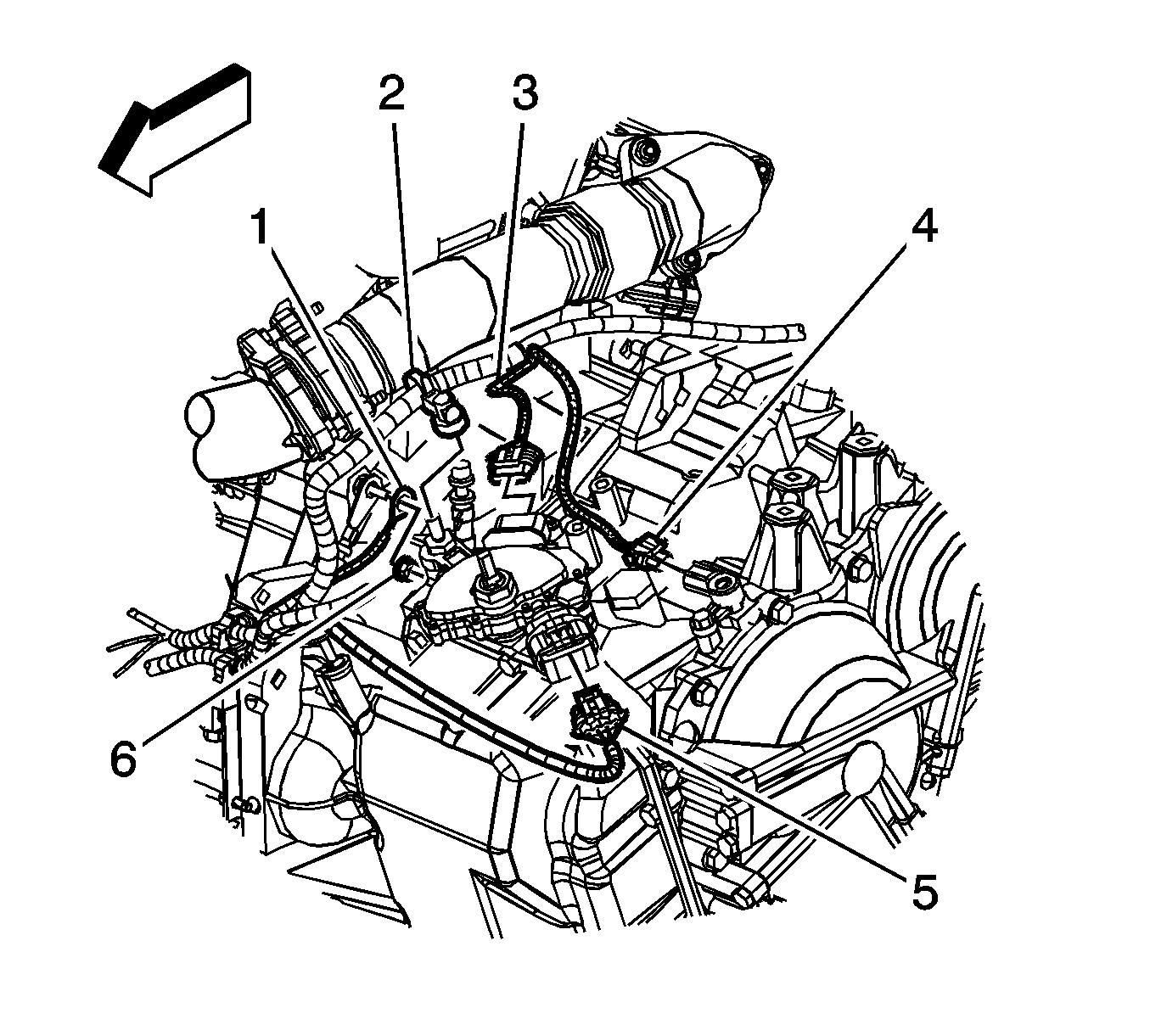
- Disconnect the electrical connector (4) from the input speed sensor.
- Disconnect the electrical connectors (3, 5) from the transaxle range switch.
- Remove the wire harness (2) from the transaxle range switch.
- Remove the nut (6) securing the battery negative cable and wire harness ground to the transaxle stud.
- Remove the battery negative cable and wire harness ground (1) from the transaxle stud.
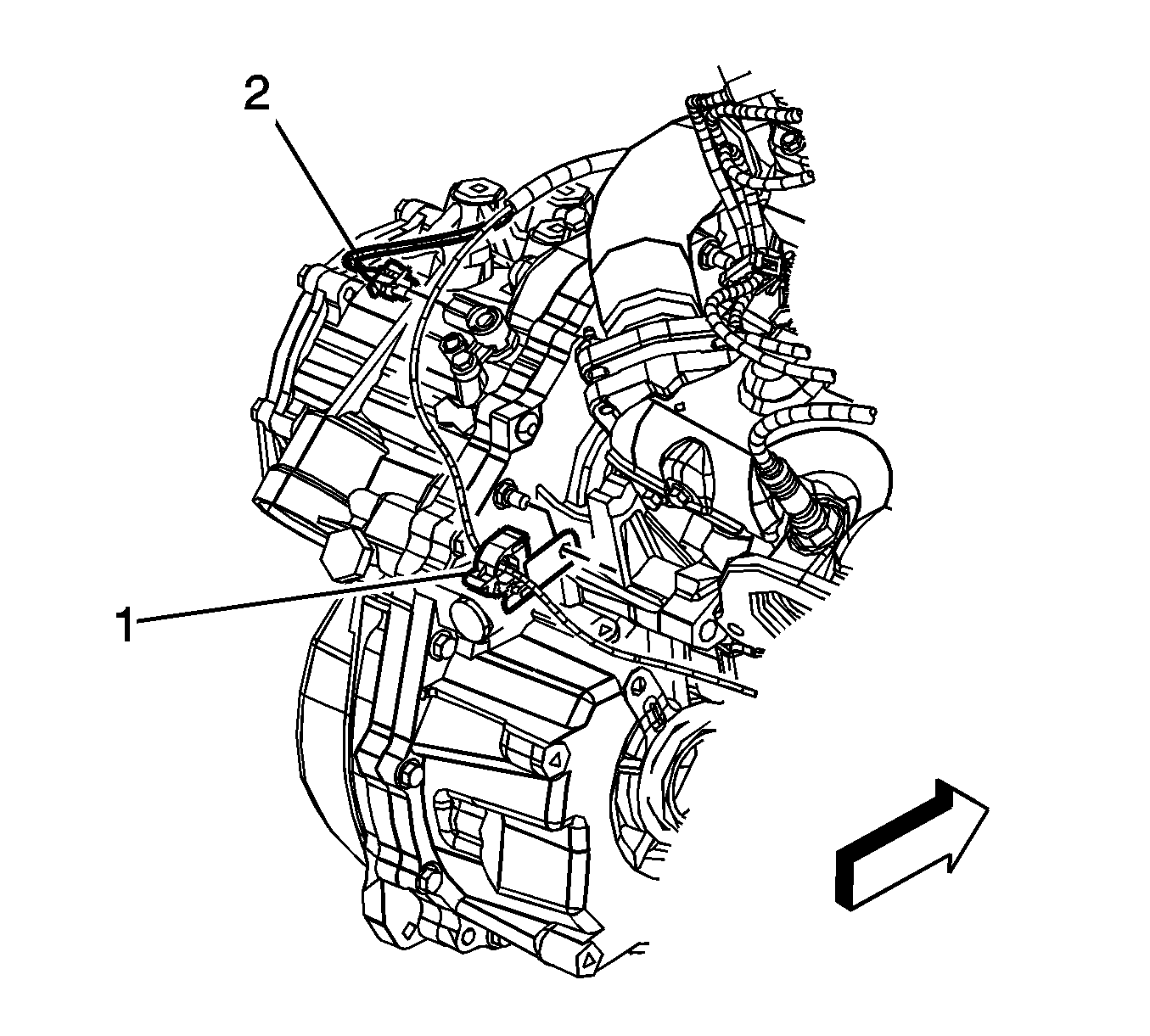
- Disconnect the electrical connector (2) from the output speed sensor.
- Remove the nut and fuel line retaining clip (1) from the transaxle.
- Disconnect the transaxle vent tube.
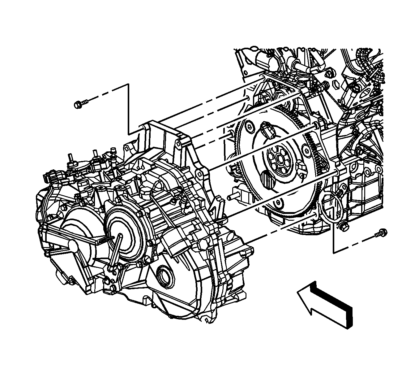
- Remove the upper 4 transaxle-to-engine bolts.
- Tie the radiator, air conditioning condenser and fan module assembly to the upper radiator support to keep the assembly with the vehicle when the frame and drivetrain are removed.
- Install the engine support fixture.
- Secure the wire harness, vent hose, and shift cable up away from the transaxle.
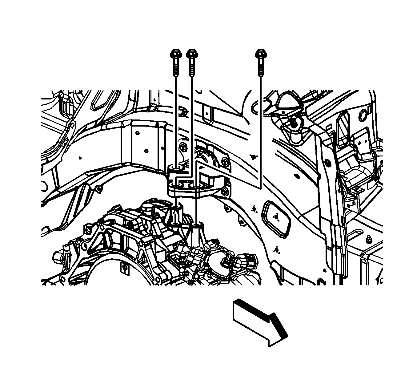
- Remove the left hand transaxle mount-to-transaxle bolts.
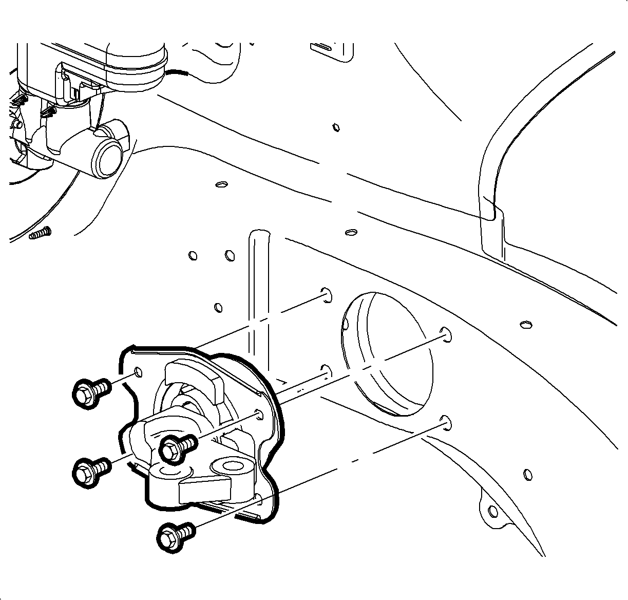
- Remove the left hand transaxle mount-to-side rail bolts.
- Remove the left hand transaxle mount from the vehicle.
- Raise and support the vehicle. Refer to
Lifting and Jacking the Vehicle.
- Remove both front wheels. Refer to
Tire and Wheel Removal and Installation.
- Remove the left and right side engine splash shields.
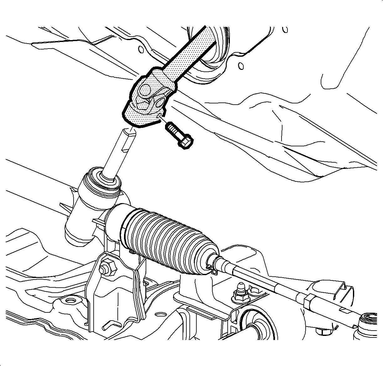
- Remove the steering intermediate shaft pinch bolt and discard the bolt.
- Disconnect the steering intermediate shaft from the steering gear.
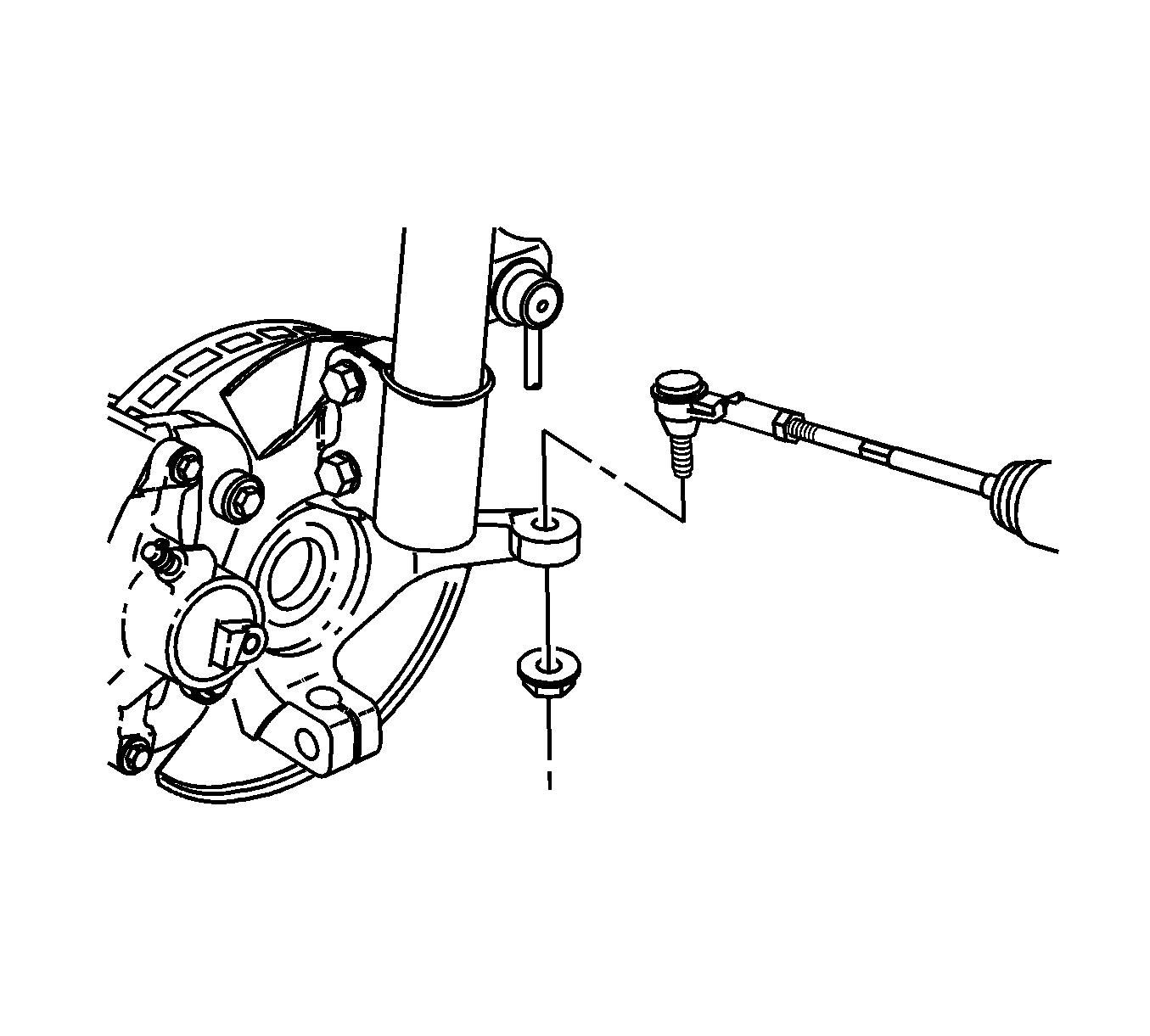
- Remove the right and left outer tie rod ends from the steering knuckles. Refer to
Steering Linkage Outer Tie Rod Replacement.
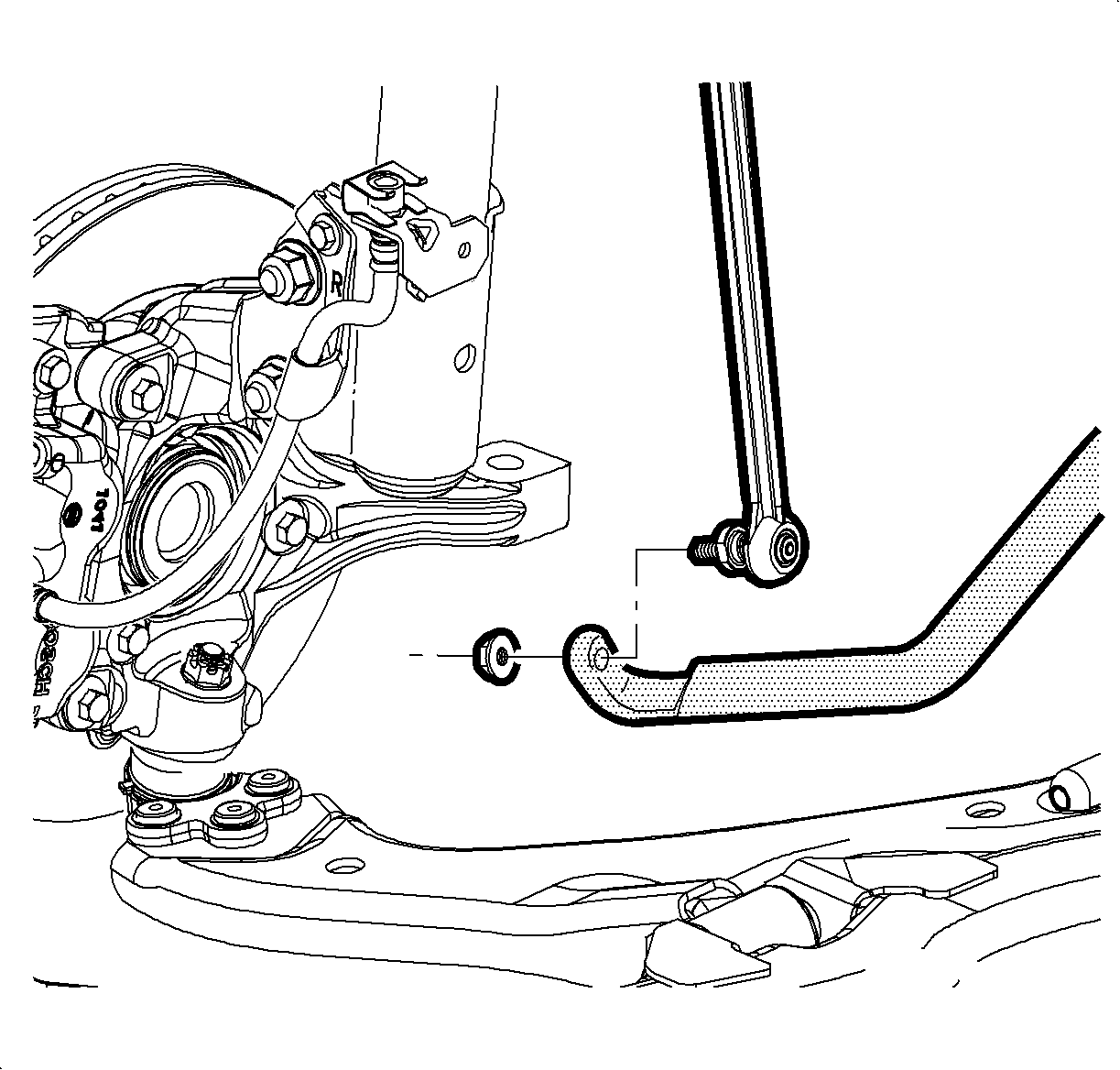
- Remove the right and left stabilizer shaft links from the stabilizer shaft. Refer to
Stabilizer Shaft Link Replacement.
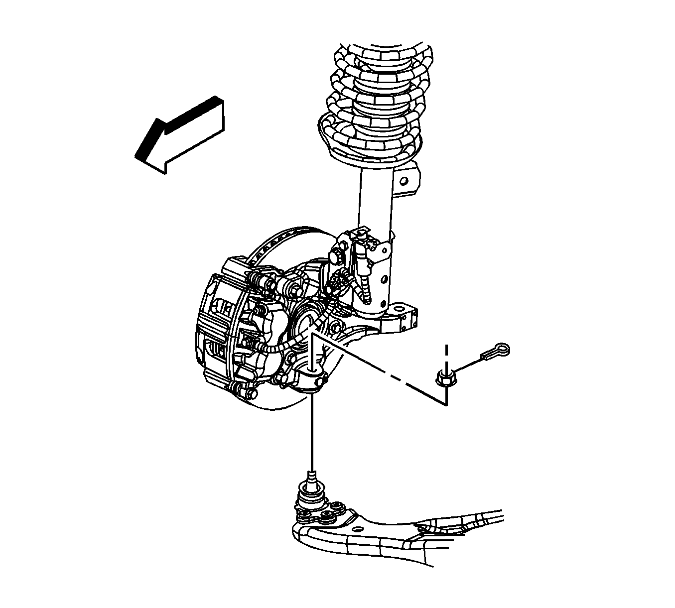
- Remove the right and left lower ball joints from the steering knuckles. Refer to
Lower Control Arm Replacement.
- Remove the front bumper fascia air deflector.
- Drain the transaxle fluid. Refer to
Transmission Fluid Replacement.
- Remove the transaxle oil cooler lines and seals from the transaxle. Refer to
Transmission Fluid Cooler Pipe Seal Replacement.
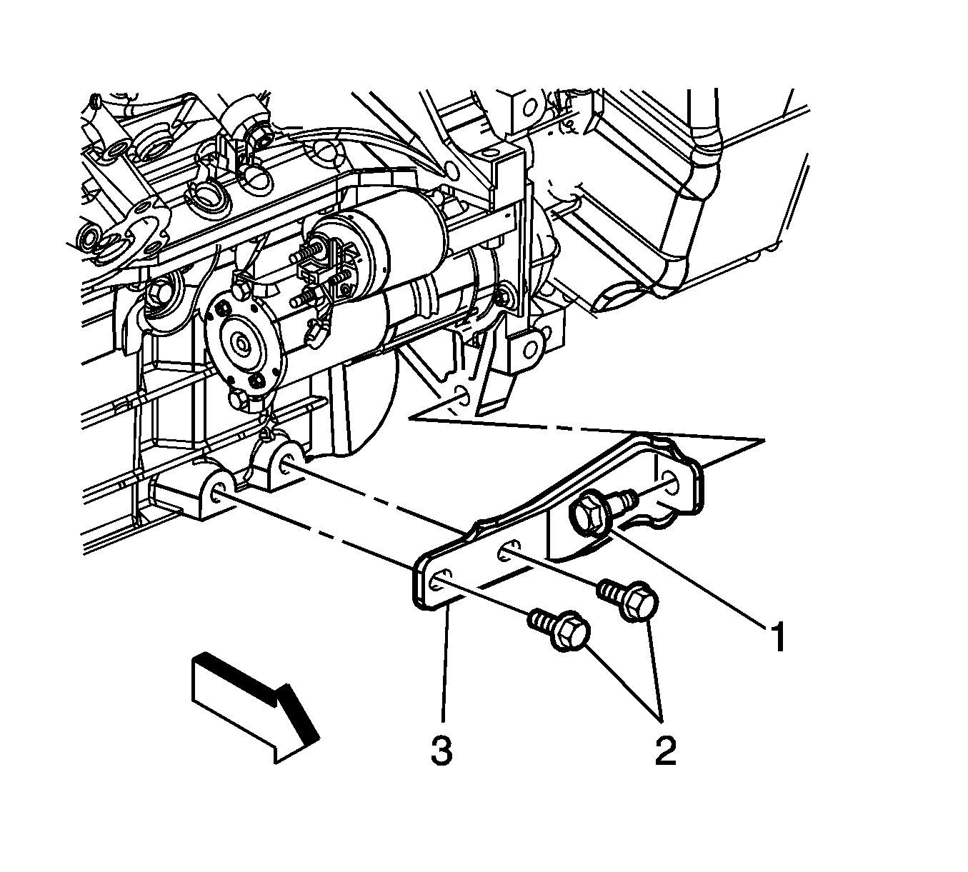
- Remove the engine-to-transaxle brace bolts (1, 2) and brace (3).
- Remove the starter motor.
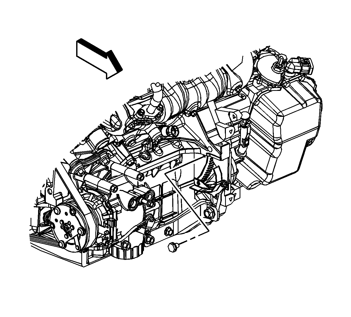
- Turn the crankshaft balancer bolt clockwise to gain access to the torque converter-to-flywheel bolts through
the starter motor hole.
Note: Mark the relation of the flywheel to torque converter for reassembly.
- Remove the torque converter-to-flywheel bolts.
- Remove the front engine mount.
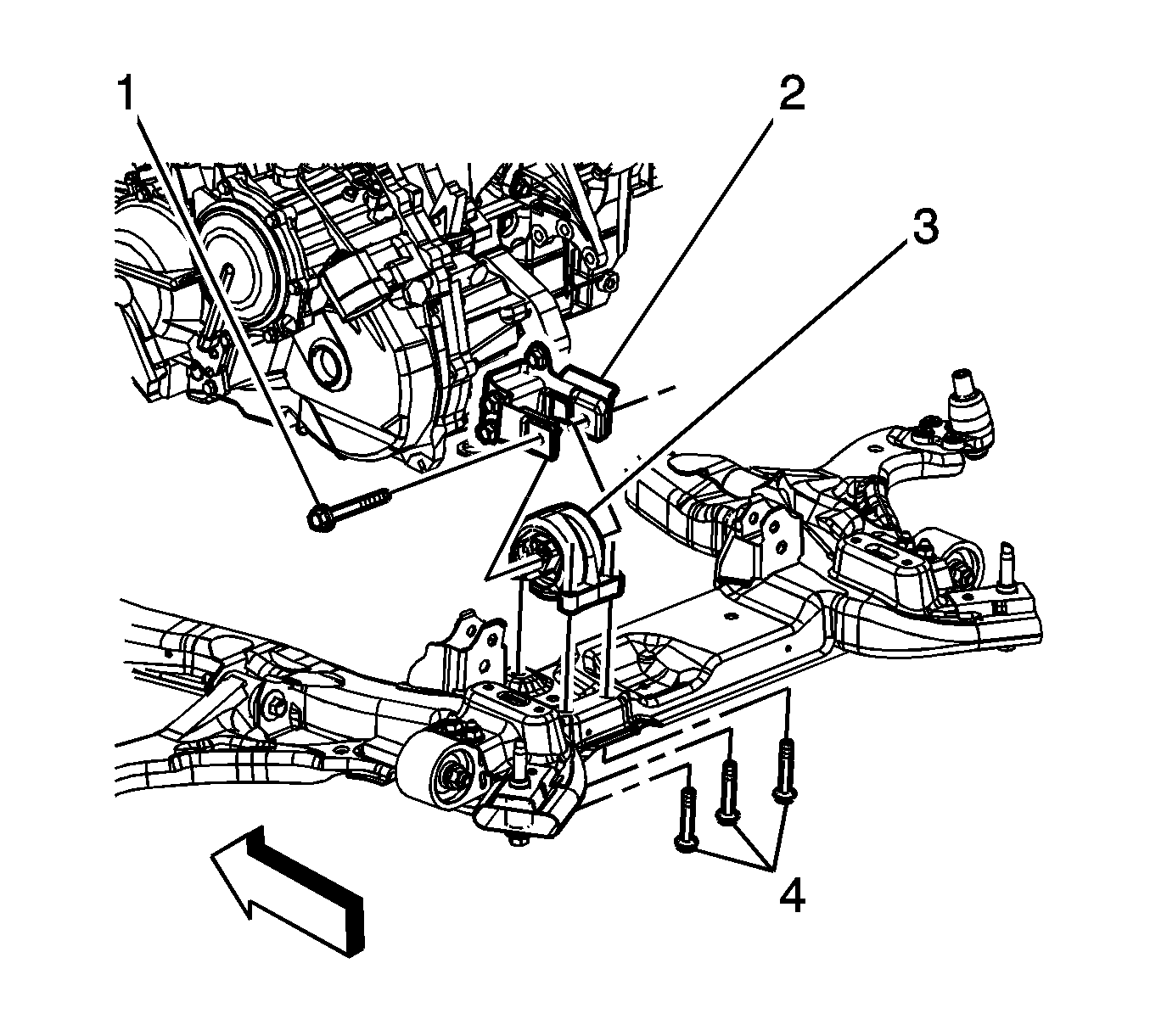
- Remove the through bolt (1) from the rear transaxle mount (3) and bracket (2).
- Place a universal frame support fixture under the frame.
- Lower the vehicle until the frame contacts the frame support fixture.
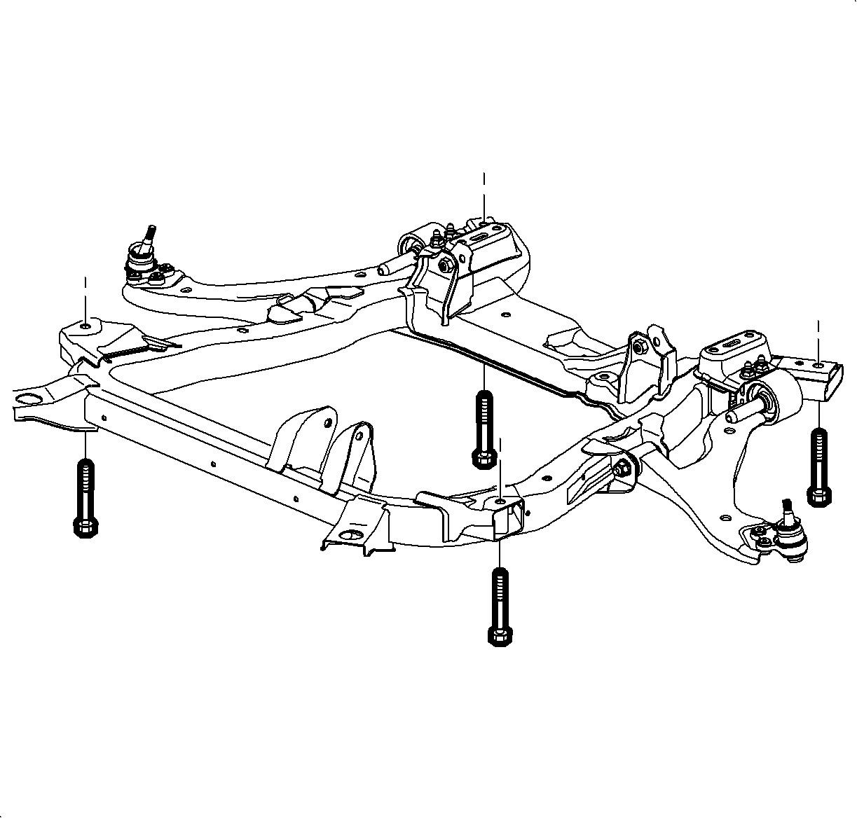
- Remove the frame-to-body bolts. Discard the bolts.
- Raise the vehicle up away from the frame and remove the frame from under the vehicle.
- Disconnect the right and left drive shafts from the transaxle. Refer to
Front Wheel Drive Shaft Replacement. Secure both drive shafts out of the way.
- If vehicle is equipped with all wheel drive (AWD) complete the following steps:
| 40.2. | Remove the transfer case mounting bracket. |
| 40.3. | Disconnect the vent hose from the top of the transfer case. |
- Support the transaxle with a suitable transaxle jack.

- Remove the 4 lower transaxle-to-engine bolts.
- Slide the transaxle away from the engine until the transaxle torque-converter clears the flywheel.
- If equipped with a drive axle seal dust cover, discard it and do not replace it.
- Lower the transaxle away from the vehicle.
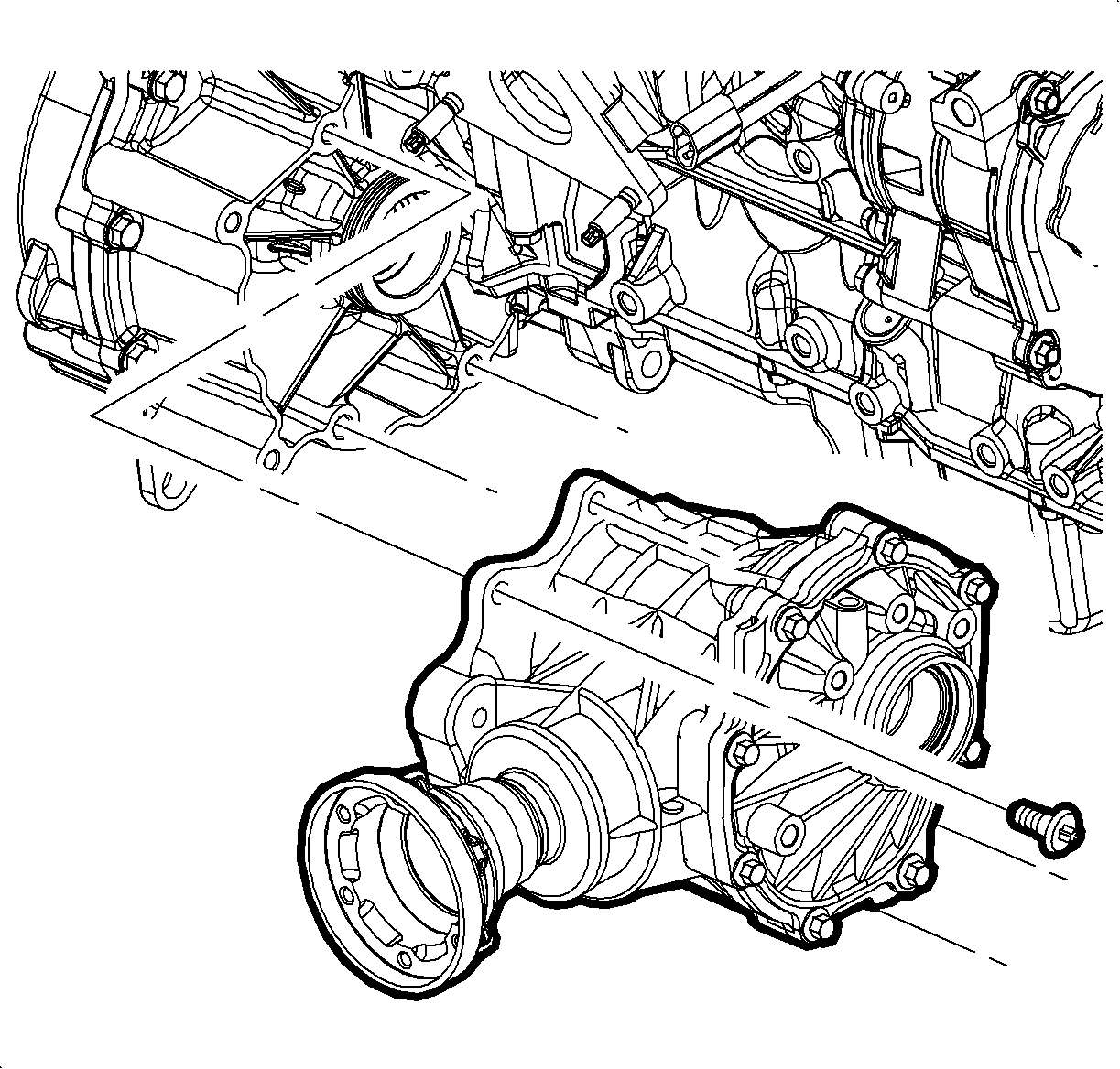
- If the vehicle is equipped with AWD complete the following steps:
| 46.1. | Remove the retaining ring from the stub shaft for tool installation. Discard the retainer ring. |
| 46.2. | Remove the stub shaft from the transfer case using the
J-6125-1B Hammer
and
J-38868 Remover and Installer
. |
| 46.3. | Remove the bolts securing the transfer case to the transaxle. |
| 46.4. | Remove the transfer case from the transaxle. |
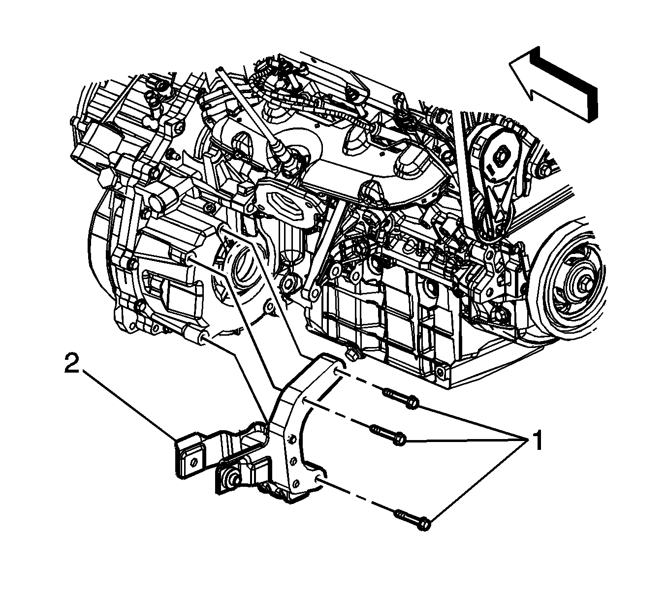
- If the vehicle is equipped with front wheel drive (FWD) complete the following steps:
| 47.1. | Remove the bolts (1) securing the rear transaxle mount bracket to the transaxle. |
| 47.2. | Remove the rear transaxle mount bracket (2) from the transaxle. |
Installation Procedure
Caution: Refer to Fastener Caution in the Preface section.

- If the vehicle is equipped with FWD complete the following steps:
| 1.1. | Install the rear transaxle mount bracket (2) to the transaxle. |
| 1.2. | Install the bolts (1), securing the rear transaxle mount bracket to the transaxle, and tighten to
55 N·m (41 lb ft). |

- If the vehicle is equipped with AWD complete the following steps:
| 2.1. | Install the transfer case to the transaxle. |
| 2.2. | Install the bolts, securing the transfer case to the transaxle, and tighten to
60 N·m (44 lb ft). |
| 2.3. | Install the stub shaft using the
J 6125-1B
and
J-38868 Remover and Installer
|
| 2.4. | Install a NEW retaining ring on the stub shaft. |
- Raise the transaxle up into the vehicle engine compartment.

- Align and install the transaxle to the engine.
- Install the 4 lower transaxle-to-engine bolts and tighten to
75 N·m (55 lb ft).
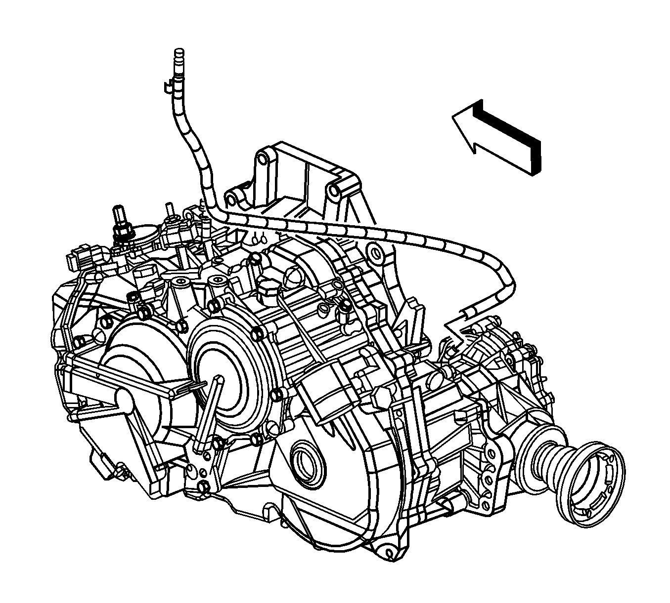
- If the vehicle is equipped with AWD complete the following steps:
| 6.1. | Connect the vent hose to the top of the transfer case. |
| 6.2. | Install the transfer case mounting bracket. |
- Install the right and left drive shafts to the intermediate shaft and transaxle. Refer to
Front Wheel Drive Shaft Replacement.

- Install the frame to the vehicle.
- Install NEW frame-to-body bolts and tighten to
155 N·m (114 lb ft).

- Install the bolt (1) through the rear transaxle mount (3) and transaxle mount bracket (2) and tighten to
110 N·m (80 lb ft).
- Install the front engine mount.

- Turn the crankshaft balancer bolt clockwise to gain access to the torque converter-to-flywheel bolts through
the starter motor hole.
Note: Align the reference marks on the flywheel and torque converter.
- Install the torque converter to flywheel bolts and tighten to
60 N·m (44 lb ft).
- Install the starter motor.

- Install the engine-to-transaxle brace (3).
- Install the engine-to-transaxle brace bolts (1, 2) and tighten to
50 N·m (37 lb ft).
- Install the transaxle oil cooler lines and seals to the transaxle. Refer to
Transmission Fluid Cooler Pipe Seal Replacement.
- Install the front bumper fascia air deflector.

- Install the right and left lower ball joints to the steering knuckles. Refer to
Lower Control Arm Replacement.

- Install the right and left stabilizer shaft links to the stabilizer shaft. Refer to
Stabilizer Shaft Link Replacement.

- Install the right and left outer tie rod ends to the steering knuckles. Refer to
Steering Linkage Outer Tie Rod Replacement.

- Connect the steering intermediate shaft to the steering gear.
- Install a NEW pinch bolt to the steering intermediate shaft and tighten to
34 N·m (25 lb ft).
- Install the right and left side engine splash shields.
- Install both front wheels. Refer to
Tire and Wheel Removal and Installation.
- Lower the vehicle.

- Install the left hand transaxle mount to the vehicle.
- Install the left hand transaxle mount-to-side rail bolts and tighten to
37 N·m (27 lb ft).

- Install the left hand transaxle mount to transaxle bolts and tighten to
50 N·m (37 lb ft).
- Remove the engine support fixture.
- Untie the radiator, air conditioning condenser and fan module assembly from the upper radiator support.

- Install the upper 4 transaxle-to-engine bolts and tighten to
75 N·m (55 lb ft).
- Connect the transaxle vent tube.

- Connect the electrical connector (2) to the output speed sensor.
- Install the nut and fuel line retaining clip (1) to the transaxle and tighten to
25 N·m (18 lb in).

- Install the battery negative cable and wire harness ground (1) to the transaxle stud.
- Install the nut (6) securing the battery negative cable and wire harness ground to the transaxle stud and tighten to
45 N·m (33 lb ft).
- Connect the electrical connectors (3, 5) to the transaxle range switch.
- Connect the electrical connector (4) from the input speed sensor.
- Install the shift control cable bracket. Refer to
Shift Control Cable Bracket Replacement.
- Install the battery tray. Refer to
Battery Tray Replacement.
- Fill the transaxle with fluid. Refer to
Transmission Fluid Replacement.


