For 1990-2009 cars only
Special Tools
| • | EN-46111 Crankshaft Rotation Socket |
| • | KM-470-B Angular Torque Gage |
Removal Procedure
- Remove the engine assembly. Refer to Engine Replacement
- Remove the intake manifold assembly. Refer to Lower Intake Manifold Replacement
- Remove the exhaust manifold. Refer to Exhaust Manifold Replacement
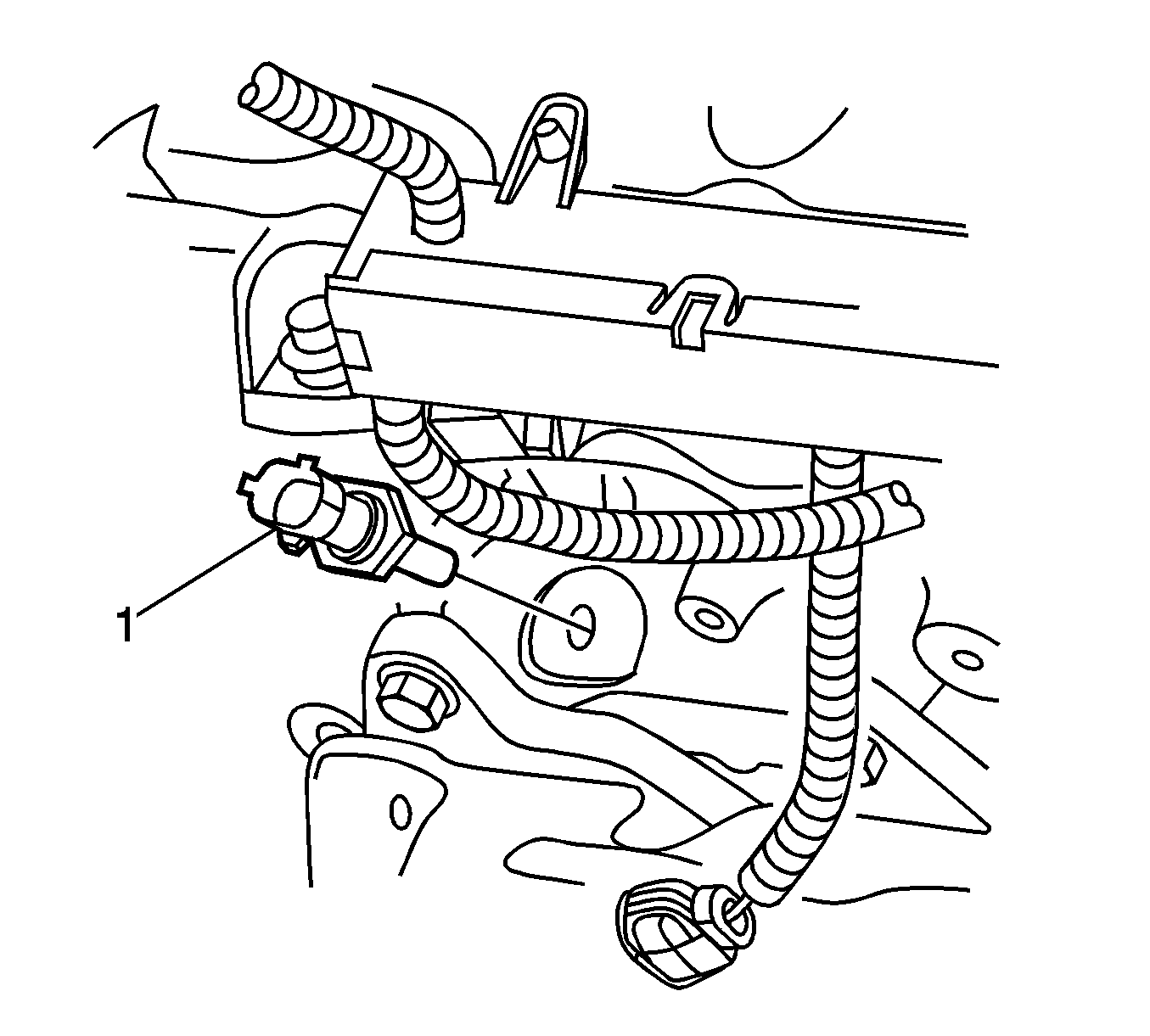
- Remove the engine coolant temperature (ECT) sensor. Refer to Engine Coolant Temperature Sensor Replacement
- Remove engine harness ground terminal attaching bolt from cylinder head.
- Remove the bank 2 secondary timing chain. Refer to Secondary Camshaft Drive Chain Replacement - Left Side
- Remove the camshaft position actuators.
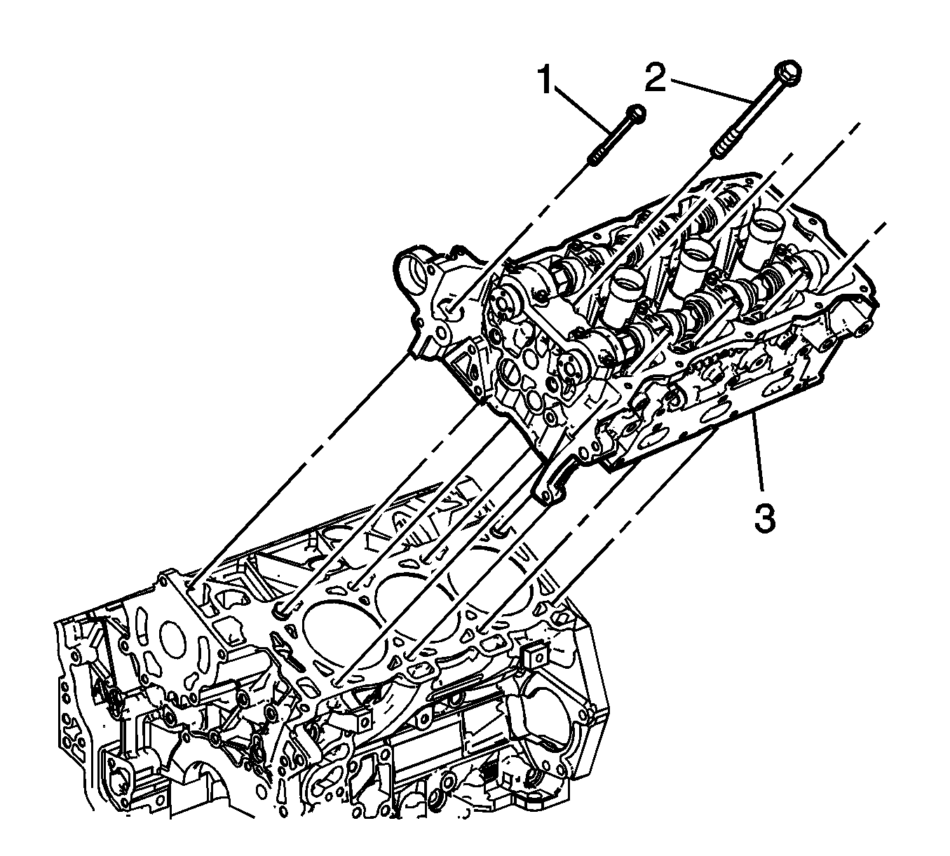
- Remove the front cylinder head attaching bolt (1), 2 places.
- Remove the cylinder head attaching bolt (2), 8 places.
- Remove the cylinder head (3).
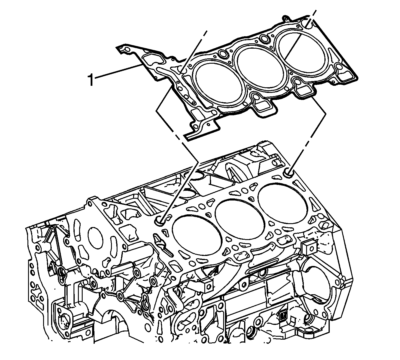
- Remove and discard the cylinder head gasket (1).
Installation Procedure
- Installation should follow the removal procedure in the reverse order.
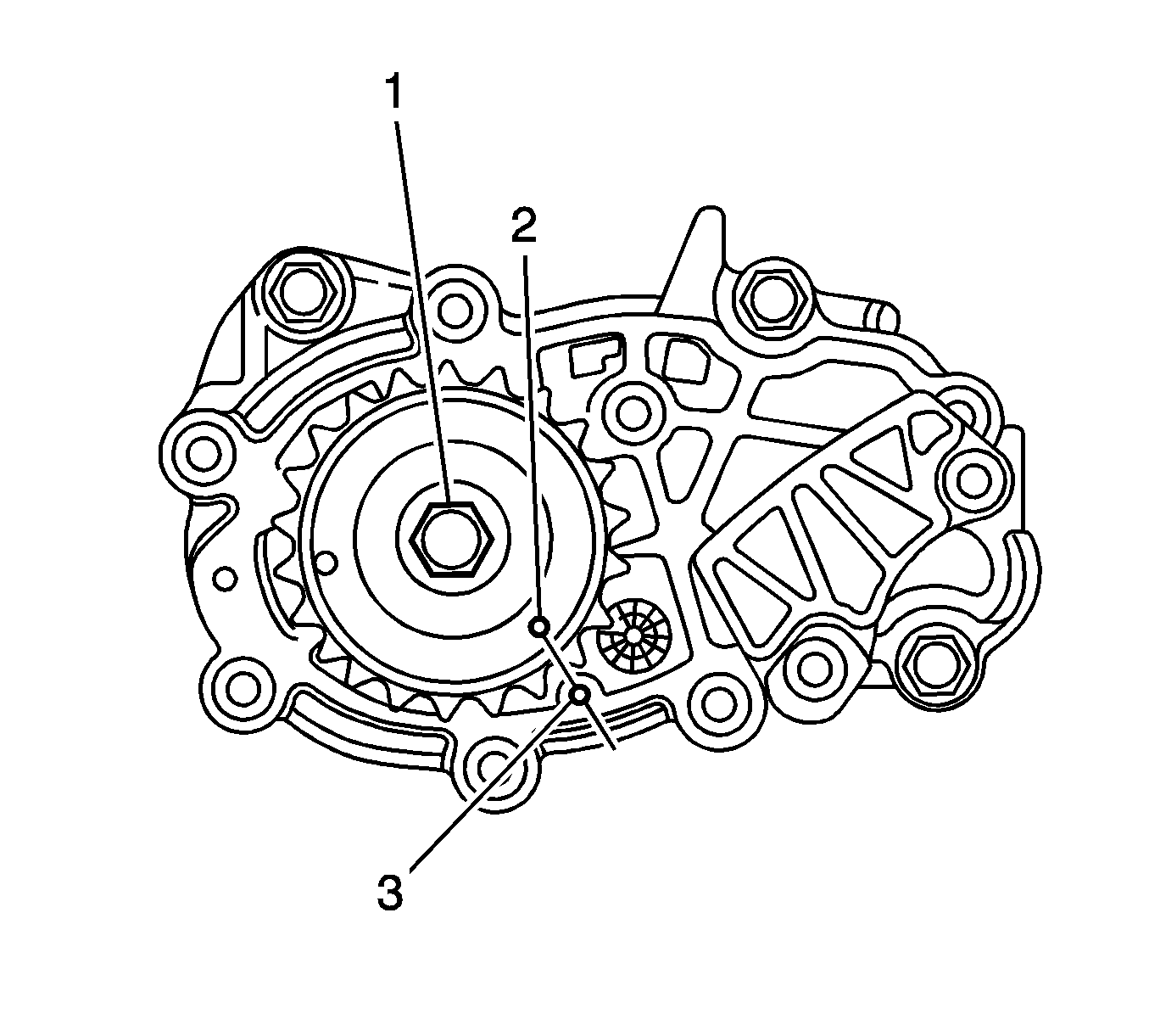
- Using EN-46111 socket (1), align the crankshaft sprocket timing mark (2) with the indexing mark (3) on the oil pump housing.
- Ensure the deck face is clean and the cylinder head locating pins are securely mounted in the cylinder block deck face.
- Install a new cylinder head gasket (1) using the deck face locating pins for retention.
- Align the cylinder head with the locating pins.
- Place the cylinder head in position on the deck face.
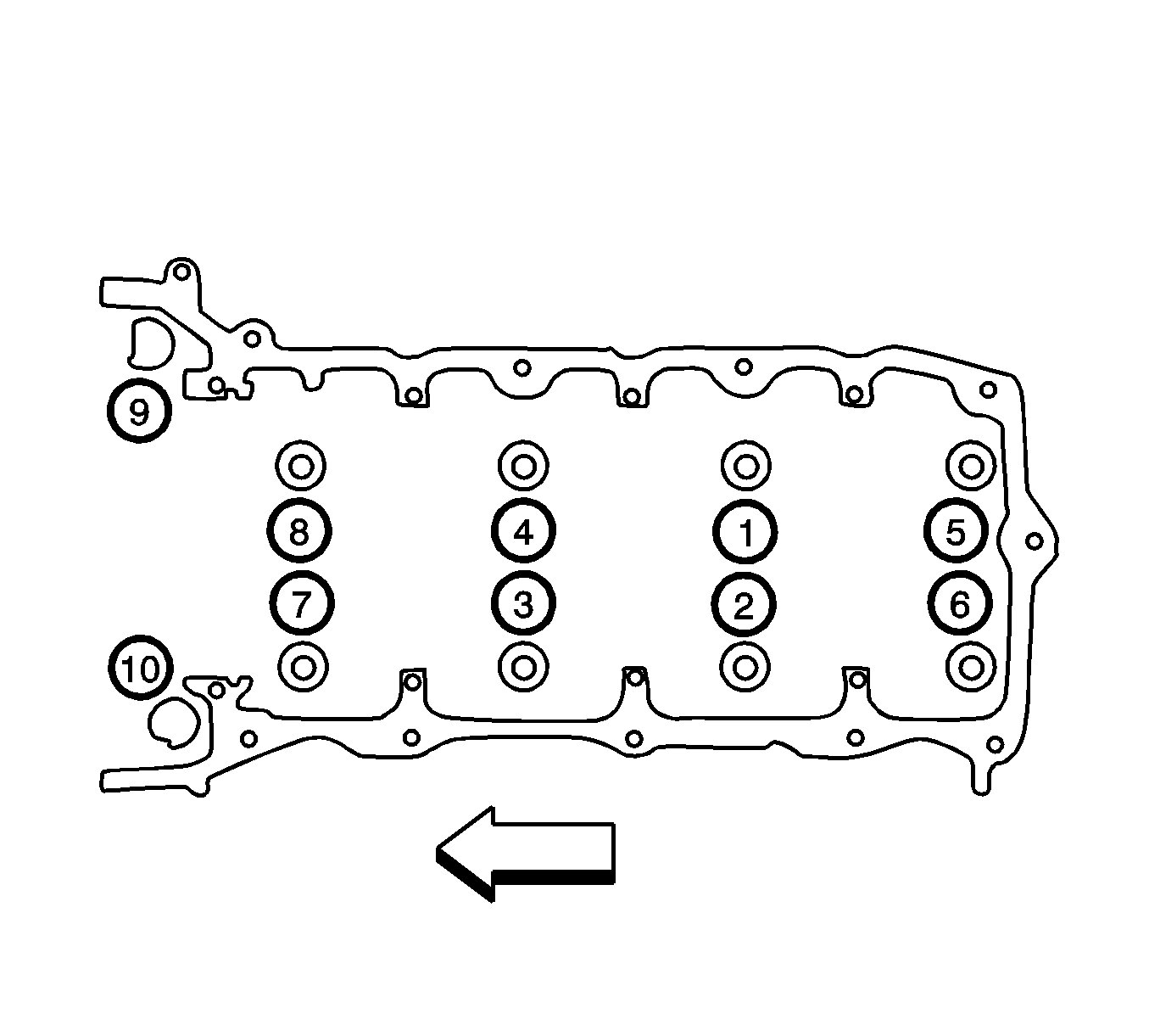
- Install new cylinder head bolt (1) and tighten in the sequence shown to 45N·m (33 lb ft) and turns the bolt another 120 degrees using KM-470-B gage .
- Install the front cylinder head bolt (2) and tighten in the sequence shown (9 and 10) to 15 N·m (11 lb ft) and turns the bolt another 60 degrees using KM-470-B gage .
- Install any other parts that were previously removed.


Caution: Refer to Fastener Caution in the Preface section.
Note: Do not allow oil on the cylinder head bolt bosses.
Note: Do not reuse the old cylinder head bolts (1 to 8 inclusive).
