For 1990-2009 cars only
Special Tools
| • | EN-46111 Crankshaft Rotation Socket |
| • | KM-470-B Angular Torque Gage |
Removal Procedure
- Remove the engine assembly. Refer to Engine Replacement.
- Remove the intake manifold assembly. Refer to Lower Intake Manifold Replacement.
- Remove the exhaust manifold. Refer to Exhaust Manifold Replacement.
- Remove engine harness ground terminal attaching bolts from the cylinder head.
- Remove the bank 1 side secondary timing chain. Refer to Secondary Camshaft Drive Chain Replacement - Right Side.
- Remove the camshaft position actuators.
- Remove the power steering fluid supply line retaining bolt from the cylinder head.
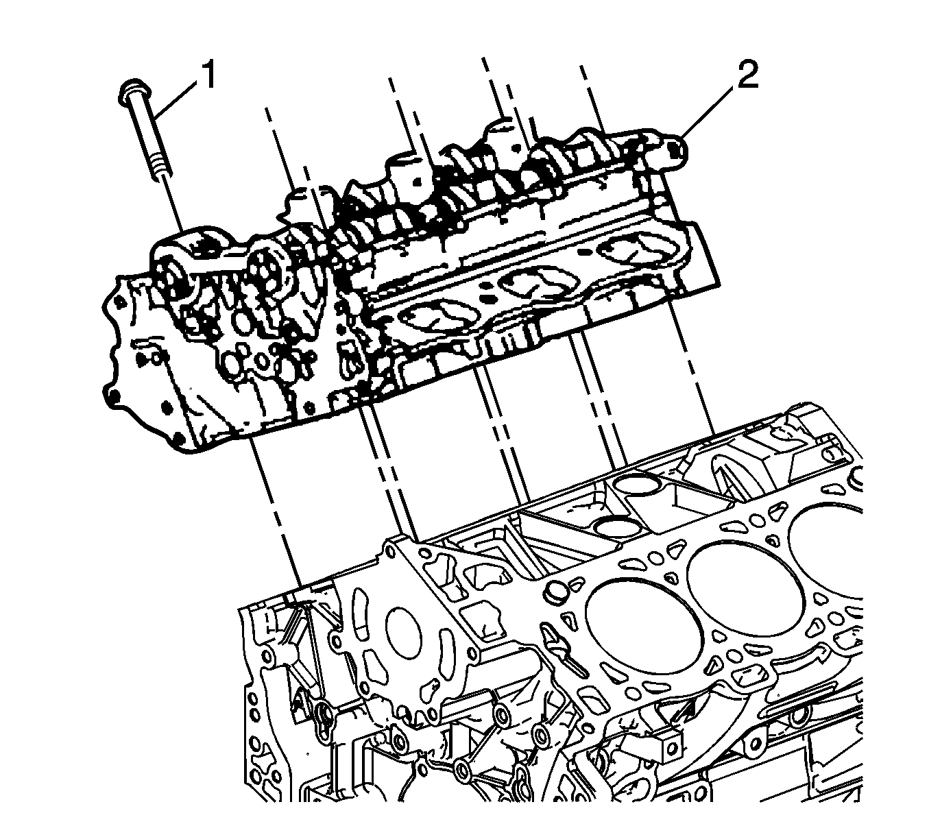
- Remove the cylinder head attaching bolt (1), eight places.
- Remove the cylinder head.
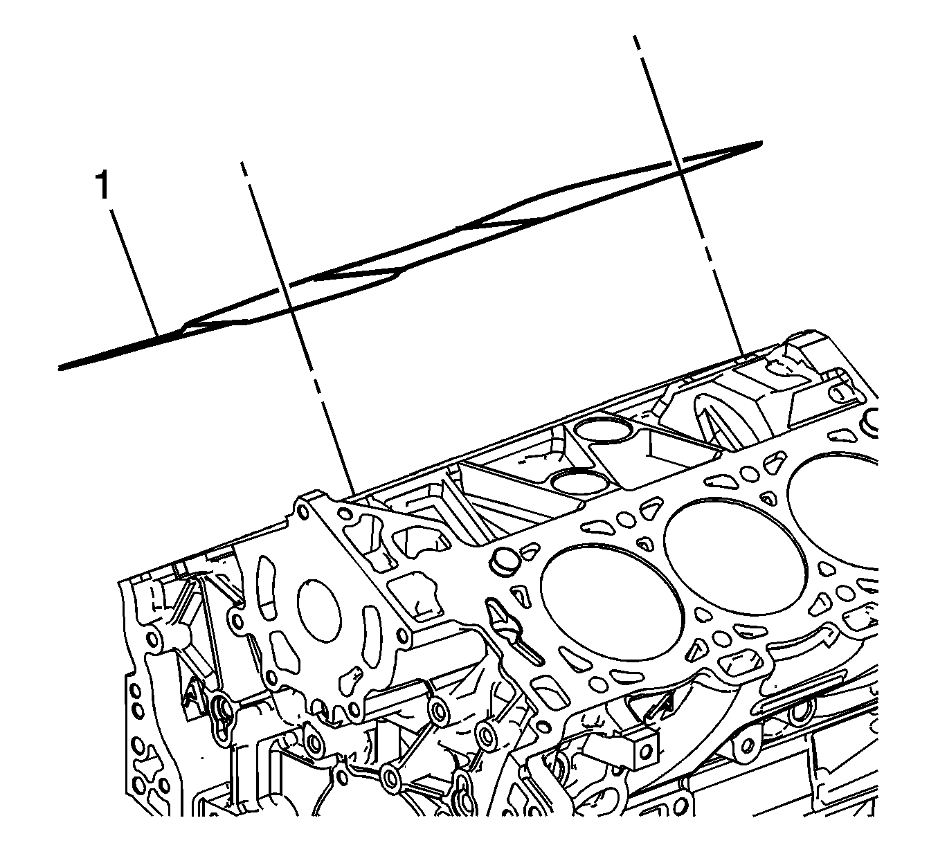
- Remove and discard the cylinder head gasket (1).

Note: There is no bolt fitted to the hole in the bank of the bank 1 cylinder head.

Installation Procedure
- Installation should follow the removal procedure in the reverse order.
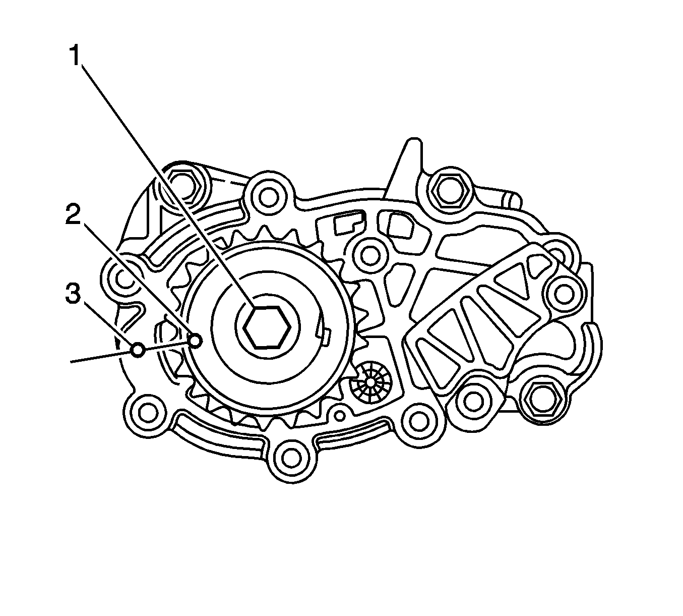
- Using EN-46111 socket (1), align the crankshaft sprocket timing mark (2) with the indexing mark (3) on the oil pump housing.
- Ensure the deck face is clean and the cylinder head locating pins are securely mounted in the cylinder block deck face.
- Install a new cylinder head gasket (1) using the deck face locating pins for retention.
- Align the cylinder head (2) with the locating pins.
- Place the cylinder head in position on the deck face.
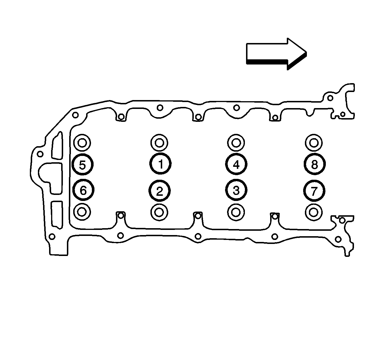
- Install the new cylinder head bolt (1) tighten in the sequence shown to 45 N·m (33 lb ft) and turn the bolt another 120 degreesKM-470-B gage .
- Install any other parts that were previously removed.


Caution: Refer to Fastener Caution in the Preface section.

Note: Do not allow oil on the cylinder head bolt bosses.
Note: Do not reuse the old cylinder head bolts (1 to 8 inclusive).
