For 1990-2009 cars only
Removal Procedure
- Disconnect the negative battery cable.
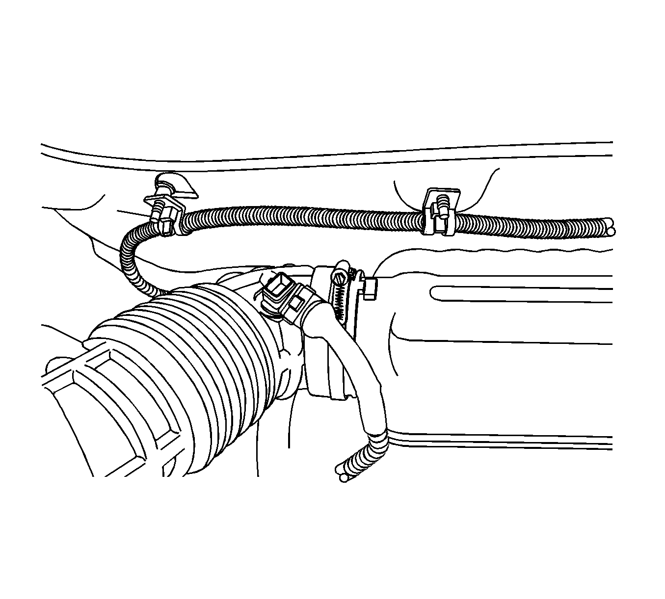
- Disconnect the intake air temperature (IAT) sensor connector.
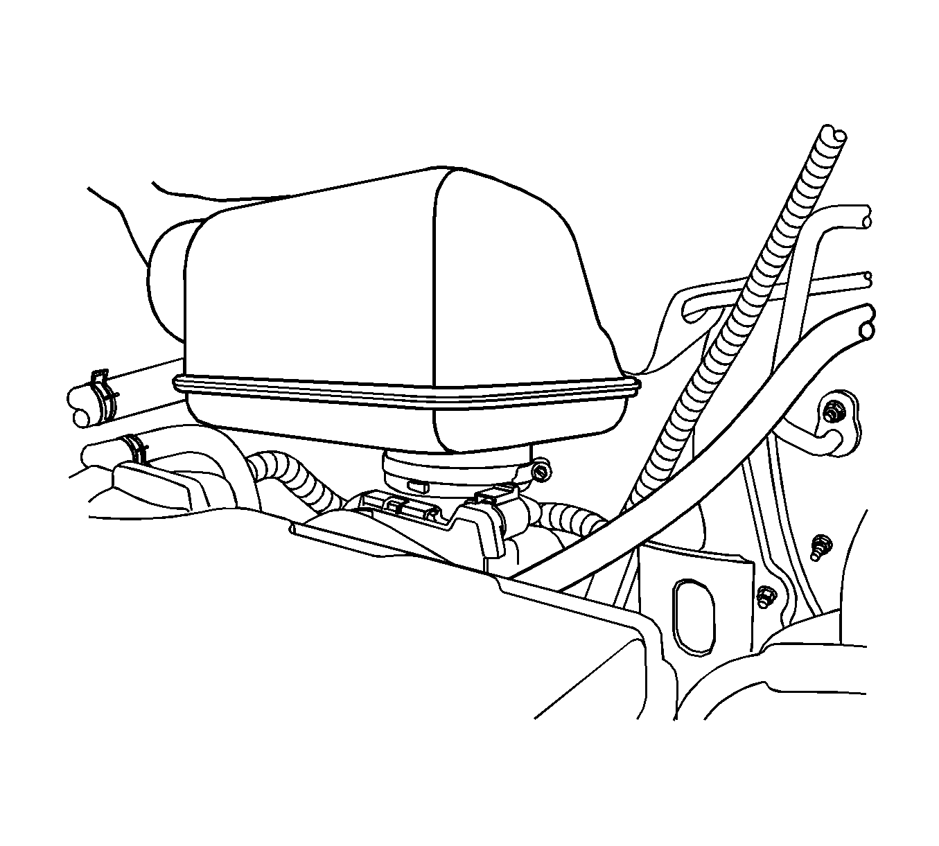
- Loosen the clamp and disconnect the air cleaner outlet hose from the resonator.
- Loosen the clamp and remove the resonator from the electronic throttle body.
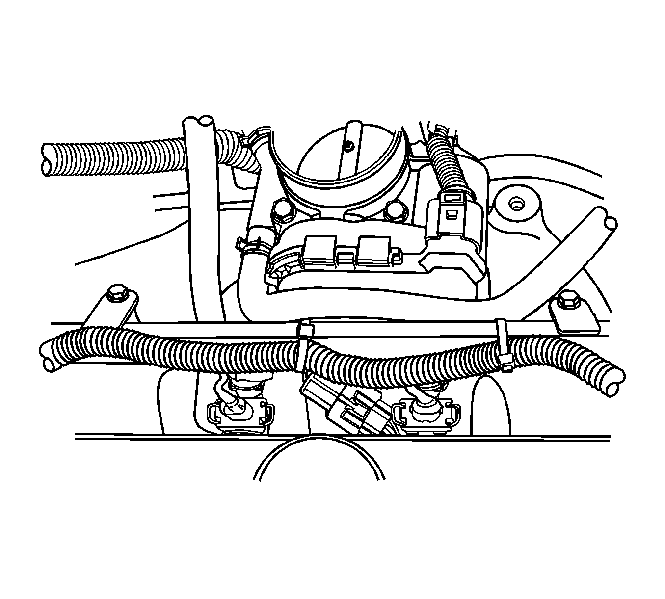
- Remove the fuel rail. Refer to Fuel Injection Fuel Rail Assembly Replacement.
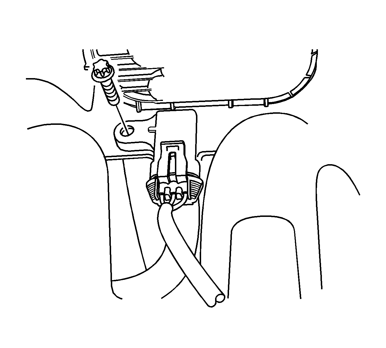
- Disconnect the manifold absolute pressure (MAP) sensor connector.
- Remove the MAP sensor retaining bolt.
- Remove the MAP sensor from the intake manifold.
Warning: Refer to Battery Disconnect Warning in the Preface section.


Installation Procedure
- Install the MAP sensor to the intake manifold.
- Install the MAP sensor retaining bolt.
- Install the fuel rail. Refer to Fuel Injection Fuel Rail Assembly Replacement.
- Connect the MAP sensor connector.
- Install the resonator to the electronic throttle body.
- Connect the air cleaner outlet hose to the resonator.
- Connect the IAT sensor connector.
- Connect the negative battery cable.

Caution: Refer to Fastener Caution in the Preface section.
Tighten
Tighten the MAP sensor retaining bolt to 4 N·m (35 lb in).

