For 1990-2009 cars only
Removal Procedure
- Raise and support the vehicle on an alignment rack. Refer to Lifting and Jacking the Vehicle.
- Remove the front tire and wheel assembly. Refer to Tire and Wheel Removal and Installation.
- Remove the front brake rotor. Refer to Front Brake Rotor Replacement.
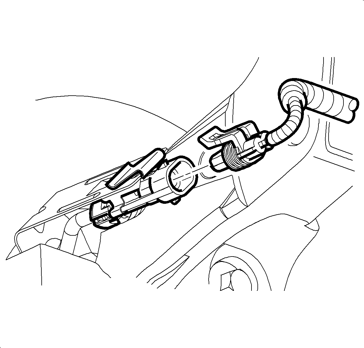
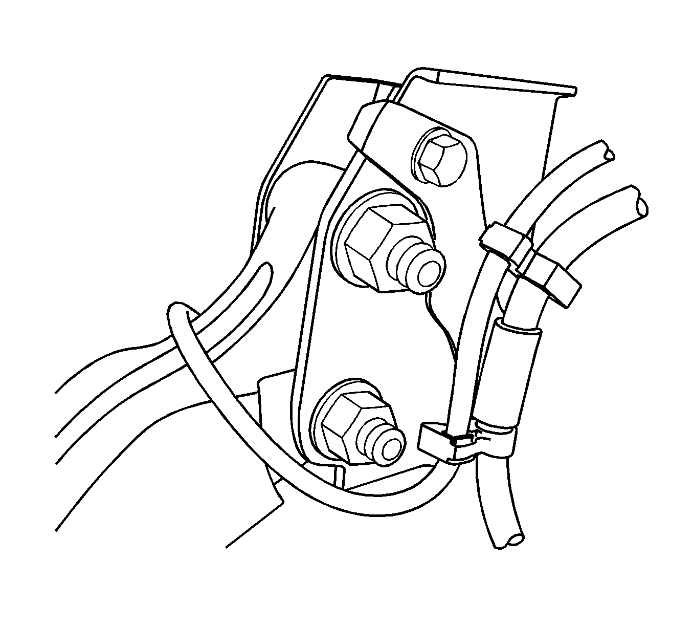
- Disconnect the wheel speed sensor electrical connector, if equipped.
- Remove the wheel speed sensor electrical connector, if equipped, from the connector bracket.
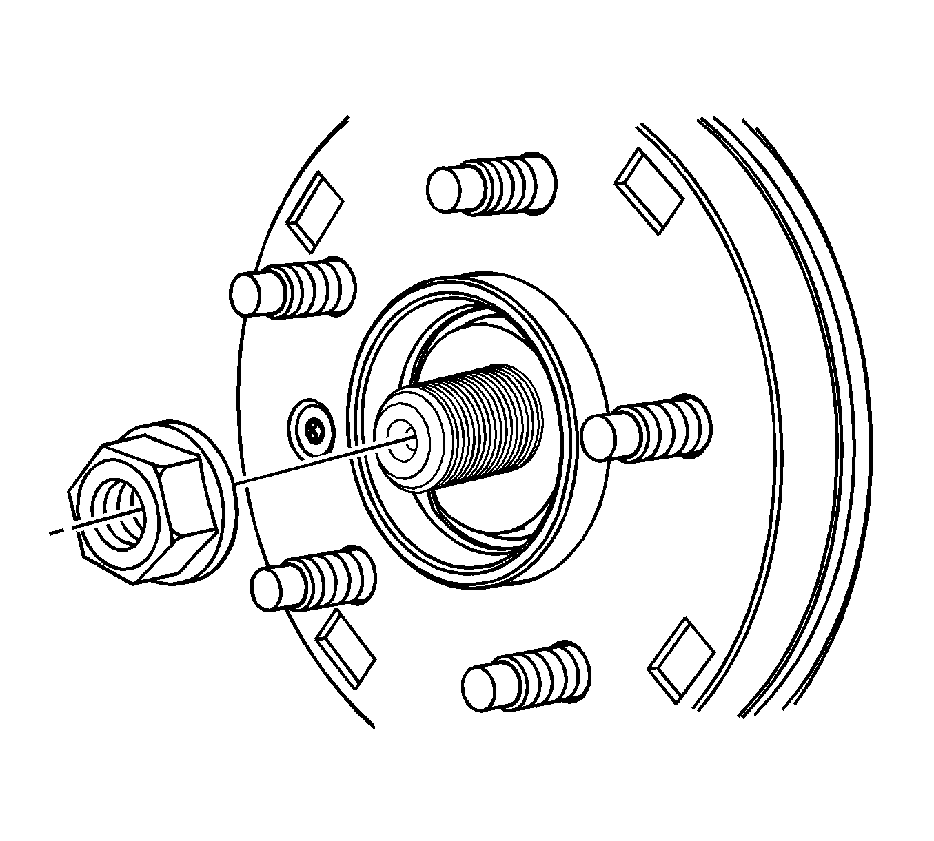
- Remove the front hub nut.
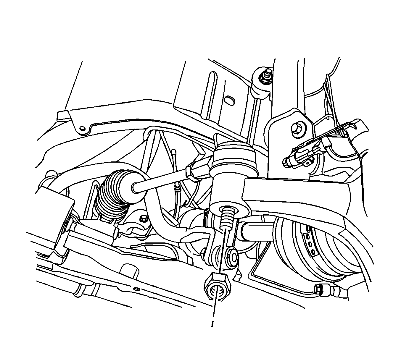
- Remove the nut that retains the outer tie rod end to the knuckle.
- Separate the outer tie rod end from the knuckle.
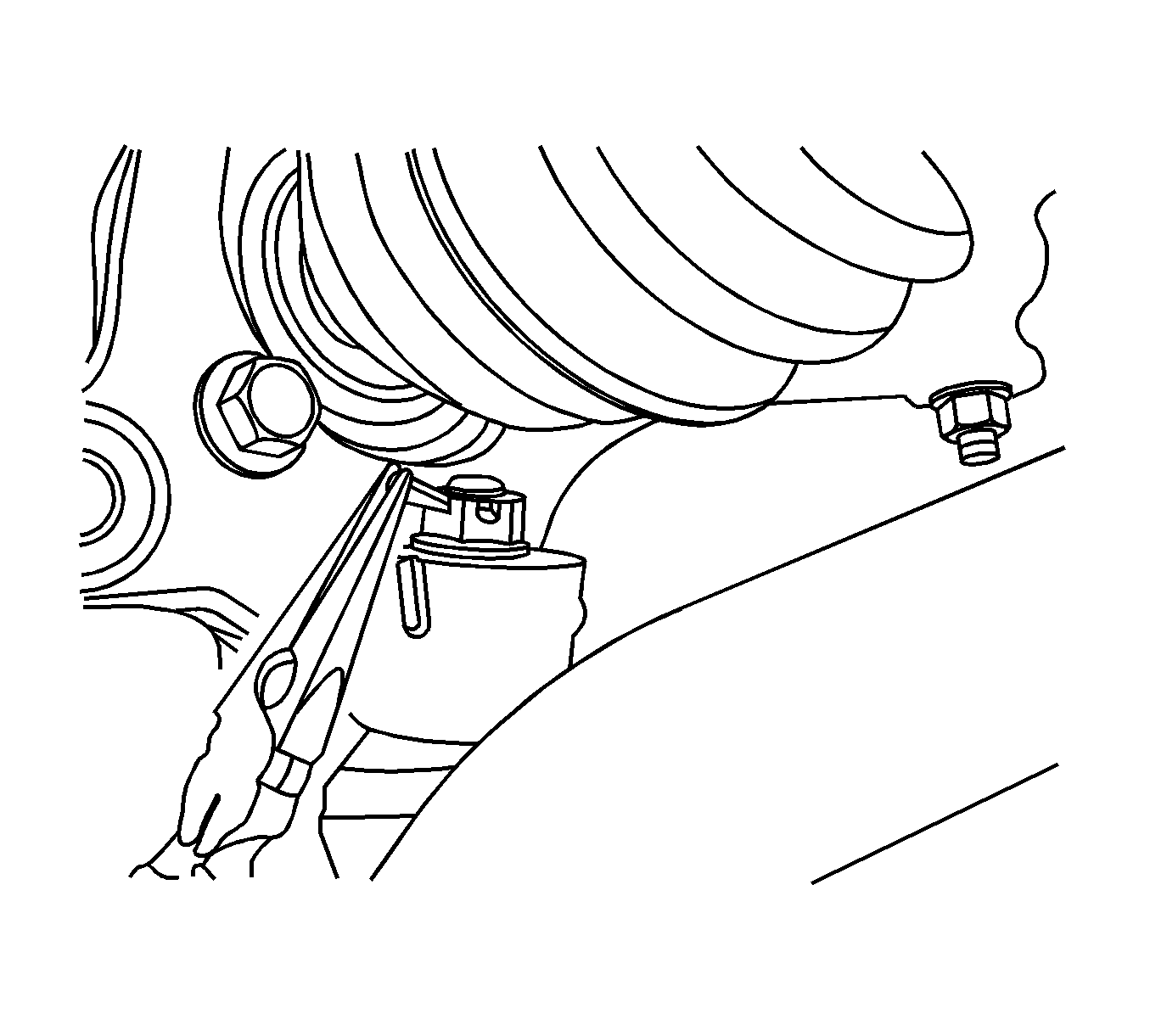
- Remove the cotter pin and the nut that retains the control arm ball joint to the knuckle.
- Separate the control arm ball joint from the knuckle.
- Support the wheel drive shaft with heavy mechanic's wire or equivalent.
- Remove the front strut to knuckle nuts and bolts.
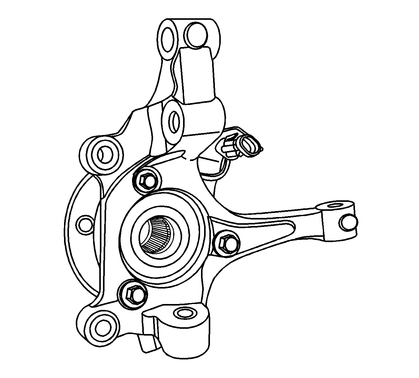
- Remove the knuckle and hub assembly from the wheel drive shaft.
- Remove the hub bolts from the knuckle and separate the hub from the knuckle.
Installation Procedure
- Install the hub to the knuckle with the bolts and tighten to 115 N·m (85 lb ft).
- Install the hub and knuckle assembly to the wheel drive shaft.
- Install the hub nut to the axle shaft and tighten to 205 N·m (157 lb ft).
- Remove the mechanic's wire from the wheel drive shaft.
- Install the knuckle to strut bolts and nuts and tighten to 180 N·m (133 lb ft).
- Install the front brake rotor. Refer to Front Brake Rotor Replacement.
- Install the control arm ball joint to the knuckle.
- Install the nut to the ball joint stud and tighten to 10 N·m (89 lb in).
- Install the cotter pin.
- Install the outer tie rod end to the knuckle.
- Install the outer tie rod nut and tighten to 50 N·m (37 lb ft).
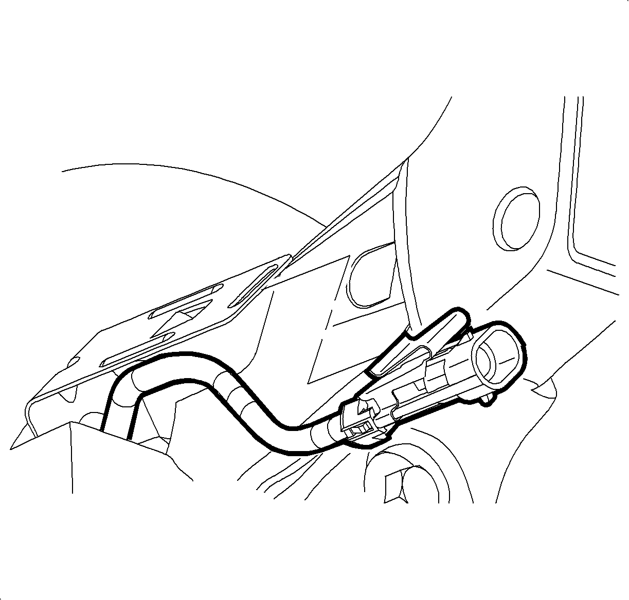
- Install the wheel speed sensor electrical connector, if equipped, to the mounting bracket.
- Connect the wheel speed sensor electrical connector, if equipped.
- Install the front tire and wheel assembly. Refer to Tire and Wheel Removal and Installation.
- Measure the wheel alignment. Adjust the wheel alignment if necessary. Refer to Wheel Alignment Measurement.
- Lower the vehicle.
Caution: Refer to Fastener Caution in the Preface section.


