For 1990-2009 cars only
- Raise and support the vehicle. Refer to Lifting and Jacking the Vehicle.
- Remove the wheel and tire assemblies. Refer to Tire and Wheel Removal and Installation.
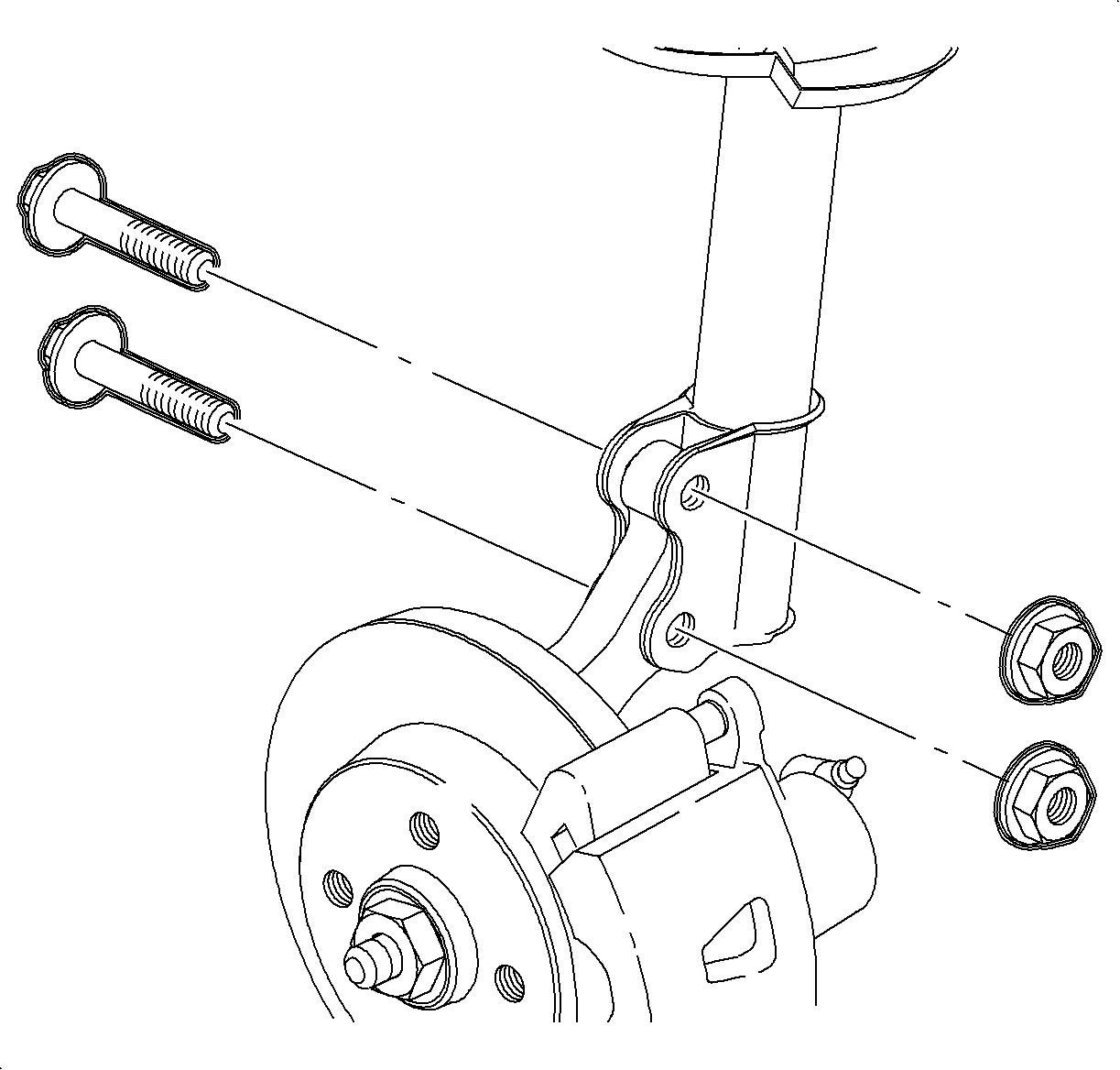
- Remove the strut to knuckle nuts and bolts. Discard the nuts and bolts.
- If the strut has not been previously modified, perform the following procedure:
- Loosely install new strut to knuckle nuts and bolts.
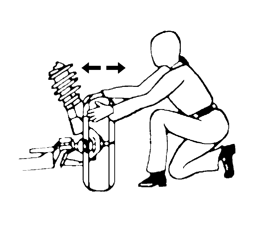
- Adjust the camber to specifications by moving the top of the wheel in or out as necessary. Refer to Wheel Alignment Specifications.
- Tighten strut to knuckle nuts and bolts.
- Install the wheel and tire assemblies. Refer to Tire and Wheel Removal and Installation.


| 4.1. | Disconnect the strut from the knuckle. |
Note:
|
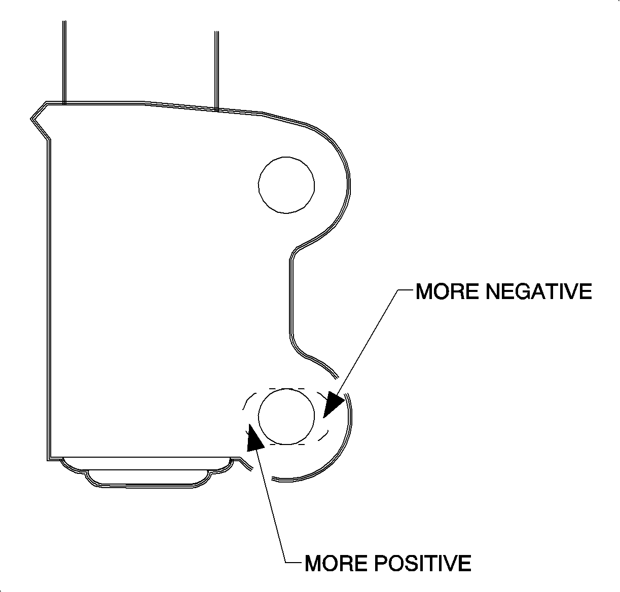
| 4.2. | If increasing negative camber, remove material from the outside of the lower strut hole. |
| 4.3. | If decreasing negative camber, remove material from the inside of the lower strut hole. |


Caution: Refer to Fastener Caution in the Preface section.
Tighten
Tighten the nuts and bolts to 180 N·m (133 lb ft).
