Removal Procedure
- If necessary, use a siphon in order to remove brake fluid from the reservoir.
- Raise and support the vehicle. Refer to Lifting and Jacking the Vehicle.
- Remove the rear tire and wheel assembly. Refer to Tire and Wheel Removal and Installation.
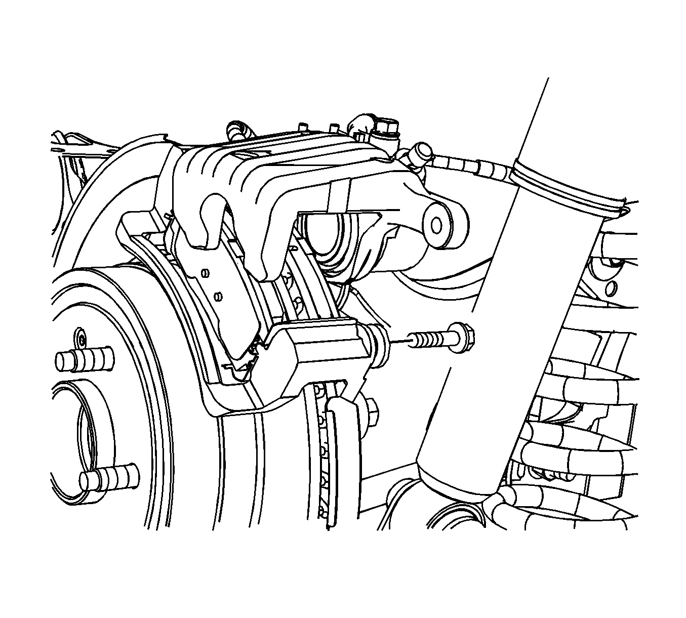
- Remove the brake caliper lower guide pin bolt.
- Pivot the caliper upward and secure the caliper with heavy mechanics wire or equivalent.
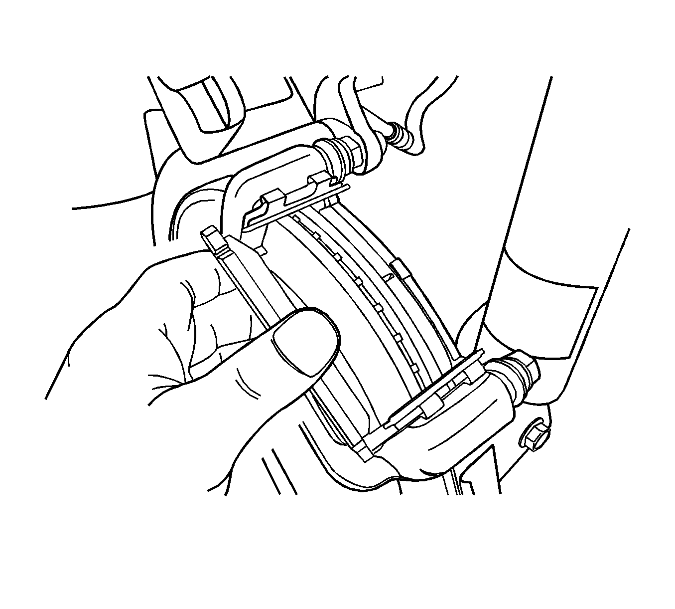
- Remove the brake pads.
Warning: Avoid taking the following actions when you service wheel brake parts:
• Do not grind brake linings. • Do not sand brake linings. • Do not clean wheel brake parts with a dry brush or with compressed air.
Warning: Brake fluid may irritate eyes and skin. In case of contact, take the following actions:
• Eye contact--rinse thoroughly with water. • Skin contact--wash with soap and water. • If ingested--consult a physician immediately.
Caution: Brake fluid will damage electrical connections and painted surfaces. Use shop cloths, suitable containers, and fender covers to prevent brake fluid from contacting these areas. Always re-seal and wipe off brake fluid containers to prevent spills.

Note: Caliper removal is not necessary in order to service the brake pads.
Caution: Support the brake caliper with heavy mechanic wire, or equivalent, whenever it is separated from its mount and the hydraulic flexible brake hose is still connected. Failure to support the caliper in this manner will cause the flexible brake hose to bear the weight of the caliper, which may cause damage to the brake hose and in turn may cause a brake fluid leak.
Note: DO NOT disconnect the hydraulic brake flexible hose from the caliper.

Inspection Procedure
- Inspect the brake pads for wear. If the pad thickness is less than the specifications, replace the brake pads. Refer to Brake Pad Inspection.
- Inspect the disc brake hardware. Replace the components as necessary. Refer to Rear Disc Brake Mounting and Hardware Inspection.
- Inspect the caliper. Repair or replace the components as necessary. Refer to Brake Caliper Inspection.
- Measure the brake rotor thickness. Refinish or replace the rotor as necessary. Refer to Brake Rotor Thickness Measurement.
- Measure the brake rotor thickness variation. Refinish or replace the rotor as necessary. Refer to Brake Rotor Thickness Variation Measurement.
- Inspect the surface of the brake rotor. Refinish or replace the rotor as necessary. Refer to Brake Rotor Surface and Wear Inspection.
- Measure the brake rotor assembled lateral runout. Refinish or replace the rotor as necessary. Refer to Brake Rotor Assembled Lateral Runout Measurement.
Note: Refinish or replace the rotor ONLY if the condition of the rotor requires service. DO NOT refinish the rotor if the brake pads are the only components requiring service.
Installation Procedure
- Clean the surface of the piston which contacts the inner brake pad.
- Clean the surface of the caliper which contacts the outer brake pad.
- If the piston is not compressed into the caliper bore, complete the following steps:
- Install the brake pads into the caliper.
- If reusing the brake caliper guide pin bolt, prepare the guide pin bolt and the guide pin as follows:
- Apply high-temperature, high-strength threadlocker to 2/3 of the threaded length of the brake caliper guide pin bolt.
- Allow the threadlocker to cure approximately 10 minutes before installing the guide pin bolts.
- Pivot the caliper downward and install the bolt. Tighten the bolt to 44 N·m (32 lb ft).
- Install the rear tire and wheel assembly. Refer to Tire and Wheel Removal and Installation.
- Lower the vehicle.
- With the engine OFF, gradually apply and release the brake pedal several times in order to position the caliper piston.
- Fill the master cylinder reservoir, if necessary. Refer to Master Cylinder Reservoir Filling.
- Burnish the pads and the rotors. Refer to Brake Pad and Rotor Burnishing.

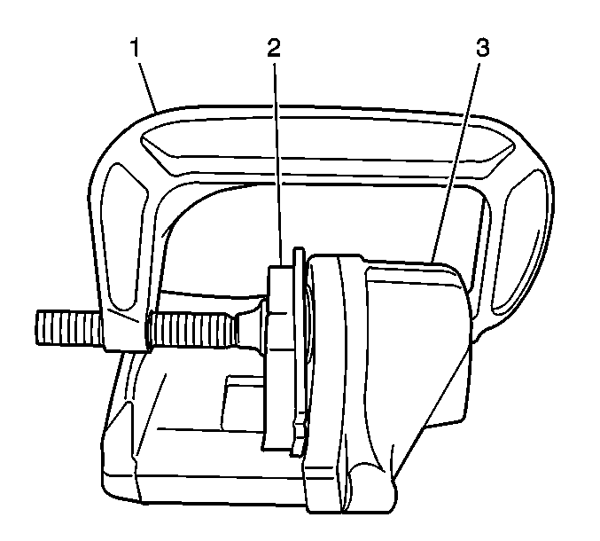
| 3.1. | Place an old brake pad (2) or a block of wood against the caliper piston. |
| 3.2. | Install a large C-clamp over the body of the brake caliper. |
Position one end of the clamp against the caliper body adjacent to the brake hose fitting.
Position the other end of the clamp against the old brake pad or the wood.
| 3.3. | Tighten the clamp in order to compress the piston into the caliper bore. |
| 3.4. | Remove the clamp and the old brake pad or the wood. |


Note: Do not damage the piston dust seal when the caliper is pulled downward to reinstall the caliper lower guide pin bolt.
Note: If reusing the brake caliper guide pin bolt, the threads of the brake caliper guide pin bolt and the threads of the guide pin must be free of threadlocker residue and debris prior to the application of threadlocker to ensure proper adhesion and fastener retention.
| 5.1. | Thoroughly clean the threadlocker residue from the guide pin bolt threads with denatured alcohol or equivalent and allow to dry. |
| 5.2. | Thoroughly clean the threadlocker residue from the guide pin threads with denatured alcohol or equivalent and allow to dry. |
Ensure there are no gaps in the threadlocker along the length of the filled area of the guide pin bolt.
Caution: Refer to Fastener Caution in the Preface section.
