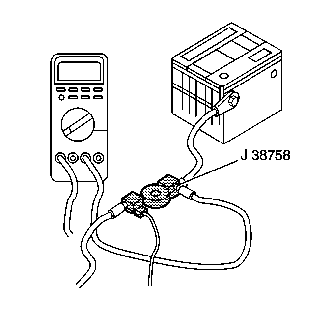
Tools Required
| • | J 38758
Parasitic Draw Test Switch |
Caution: Batteries produce explosive gases. Batteries contain corrosive acid.
Batteries supply levels of electrical current high enough to cause burns.
Therefore, in order to reduce the risk of personal injury while working
near a battery, observe the following guidelines:
| • | Always shield your eyes. |
| • | Avoid leaning over the battery whenever possible. |
| • | Do not expose the battery to open flames or sparks. |
| • | Do not allow battery acid to contact the eyes or the skin. |
| - | Flush any contacted areas with water immediately and thoroughly. |
Caution: Refer to Battery Disconnect Caution in the Preface section.
Notice: Do not turn the parasitic draw test switch to the OFF position with
the engine running. Damage will occur to the vehicle's electrical system.
Notice: The test switch must be in the ON position when removing the fuses in
order to maintain continuity in the electrical system. This avoids damaging
the digital multimeter due to accidental overloading, such as
a door being opened to change a fuse.
- Disconnect the battery negative cable.
- Turn OFF the test switch.

- Install the
J 38758
between the negative battery cable and the negative battery
terminal.
- Wait 20 minutes. Components such as ECM and EBCM have timers that draw several amps of current while they cycle down. This can give a false parasitic drain reading. Wait for these components to power down before continuing this test.
- Turn ON the test switch.
- Road test the vehicle while activating all accessories, including the radio and the air conditioning.
- Lower the door glass, then exit the vehicle. Do not move the door handle after closing the door.
- Open the hood.
- Turn OFF the ignition switch. Remove the key.
Important: From this point on, electrical continuity must be maintained in the ground circuit of the battery through the
J 38758
in the ON position or through the
J 39200
.
- Wait 20 minutes for the ECM and EBCM to power down.
- Connect a jumper wire with a 10 A fuse
J 36169-A
to the terminals of the test switch.
- Turn the test switch to the OFF position.
- Wait 10 seconds. If the fuse does not open, the current is less than 10 A. The ammeter can be used safely.
- Before the fused jumper wire is removed, turn the test switch to the ON position.
Important: If an ammeter other than the
J 39200
is used, ensure that the vehicle does not have a high current drain that would damage the ammeter when connected to the circuit.
- Perform the following procedure in order to detect a high current drain:
| 15.1. | Set the
J 39200
to the 10 A scale. |
| 15.2. | Connect the ammeter to the test switch terminals. |
| 15.3. | Turn OFF the test switch. This allows the current to flow through the ammeter. |
| 15.4. | Wait one minute, then inspect the current reading. |
| • | When there is a current reading of 2 A or less, turn ON the test switch. This maintains continuity in the electrical system. |
| • | Switch the meter down to the 2 A scale, for a more accurate reading, when the test switch is reopened. |
| 15.5. | Open the test switch. |
| 15.6. | Take the reading in milliamps. |
| 15.7. | Note the battery reserve capacity. Refer to
Battery Usage
. |
| • | Divide this number by 4. Example: 90/4=22.5 |
| • | Compare this to the ammeter reading. |
| • | The current drain in milliamps should not exceed this number. |
| • | Example: If a battery has a reserve capacity of 90 minutes, the current drain should not exceed 22 milliamps. |
When the current draw is too high, remove the electrical system fuses one at a time until the draw returns to a value less than or equal to specifications.
| • | Start with the fuses that are hot all the time. Inspect the circuits and the components that are hot all the time. |
| • | To remove the fuse, you must first open the door, which causes a high enough current flow to damage the ammeter. |
| • | Protect the ammeter, without disturbing the electrical continuity, by turning ON the test tool before opening the door. |
| • | Remove the courtesy lamp fuse. |
| • | Note the ammeter reading. |
| • | If the parasitic load is still excessive, start removing the remaining fuses one at a time. |
| • | Keep the courtesy lamp fuse out during diagnosis, so the door can remain open. |
| • | Perform Steps 11-13 each time a fuse is removed. |
| 15.9. | Removing the ECM fuse should cause a drop of less than 10 milliamps. A drop greater than 10 milliamps indicates a possible short to ground. No drop in the milliampere reading indicates the ECM is not drawing current. |
| 15.10. | Repeat the parasitic current drain test procedure after any repair has been completed. |
| 15.11. | When the cause of the excessive current draw has been located and repaired, remove the ammeter and the parasitic draw test switch. |
Notice: Refer to Fastener Notice in the Preface section.
| 15.12. | Connect the battery negative cable to the negative battery terminal. |
Tighten
Tighten the battery negative cable bolt to 4.5 N·m (40 lb in).

