For 1990-2009 cars only
Special Tools
KM-333-A Ball Joint Remover
Removal Procedure
- Raise and suitably support the vehicle. Refer to Lifting and Jacking the Vehicle. Let the control arms hang free.
- Remove the wheel. Refer to Tire and Wheel Removal and Installation.
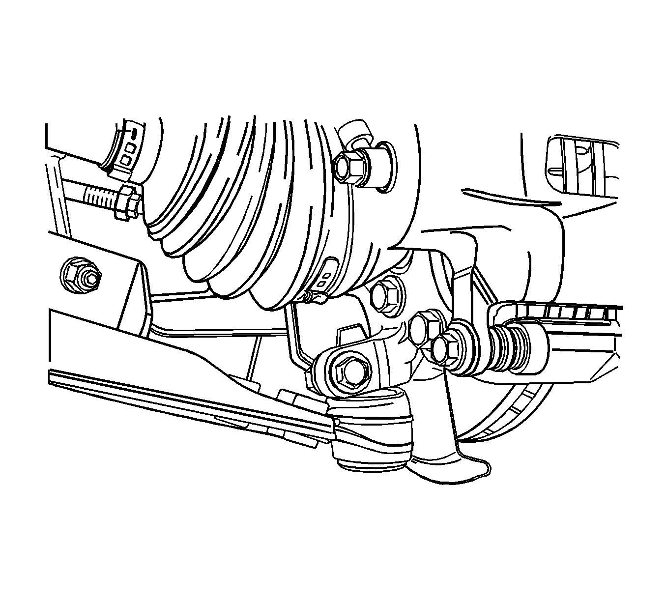
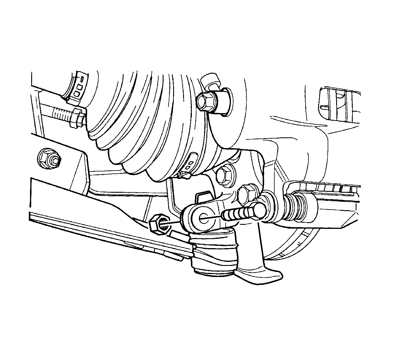
- Remove the control arm joint bolt.
- Disconnect the ball joint from the knuckle assembly using the KM-333-A .
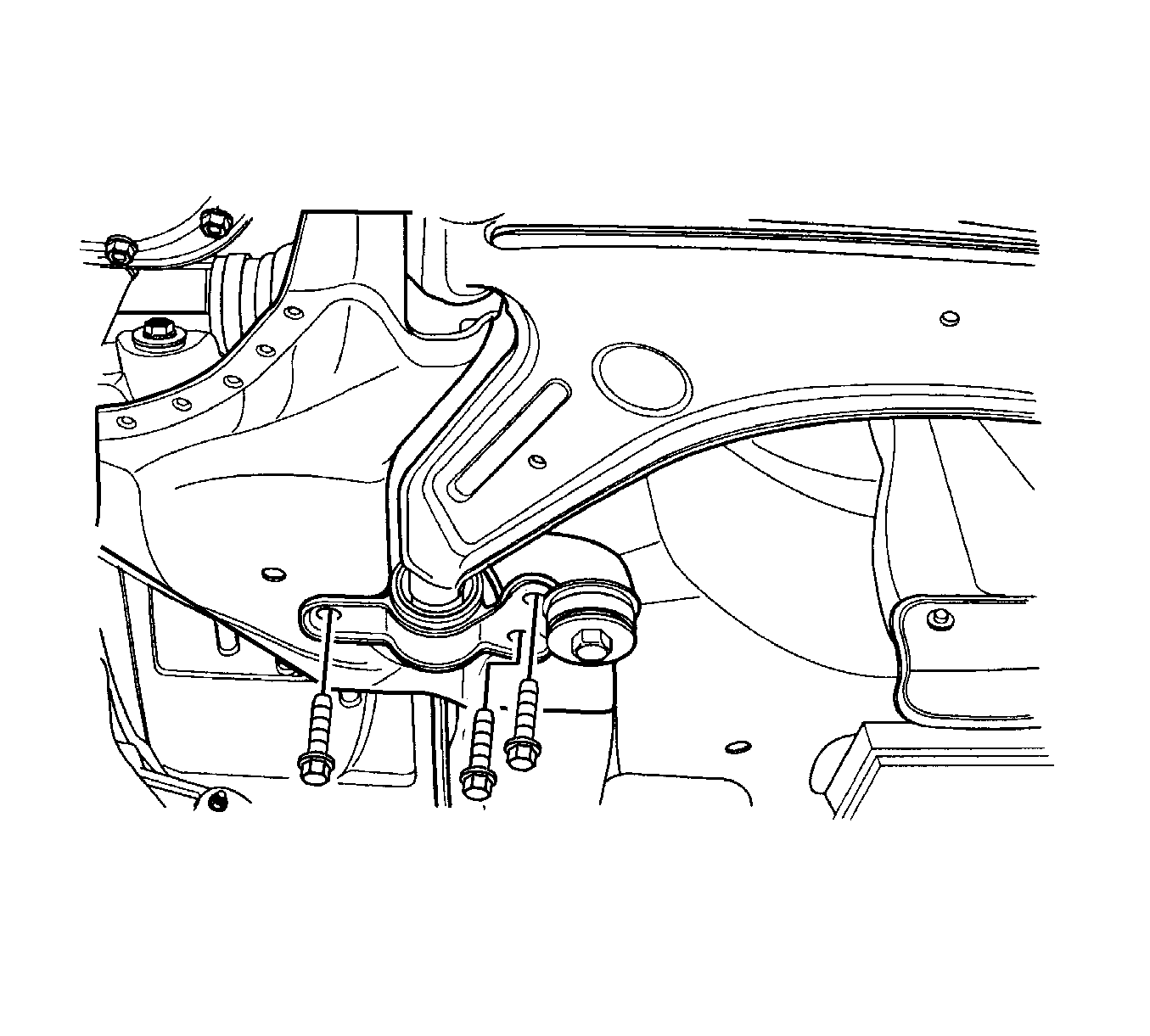
- Remove the control arm bracket bolts.
- Remove the stabilizer link.
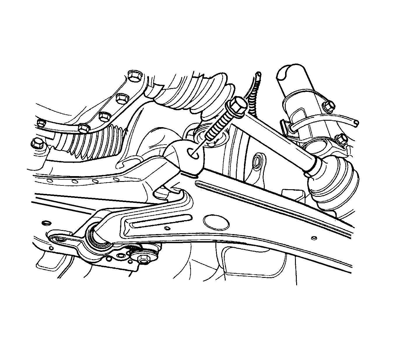
- Remove the control arm bolt and control arm assembly.
- Remove the control arm bracket from the control arm by removing the nut.
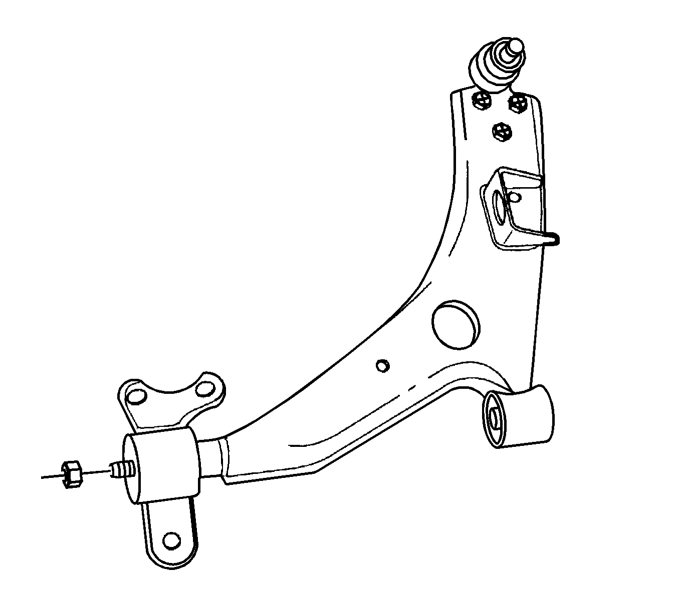
Installation Procedure
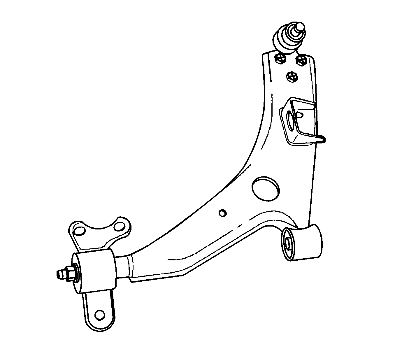
- Install the control arm bracket bolt and tighten to 110 N·m (81 lb ft).
- Install the control arm bracket bolts and control arm bolt.
- Install the stabilizer link.
- Install the control arm joint bolt and tighten to 110 N·m (81 lb ft).
Caution: Refer to Fastener Caution in the Preface section.
Note: The weight of the vehicle must be supported by the control arms before the stabilizer link-to-control arm nuts or the stabilizer shaft-to-stabilizer link nuts are tightened. This can be done by lowering the vehicle onto jackstands under the control arms have been installed.
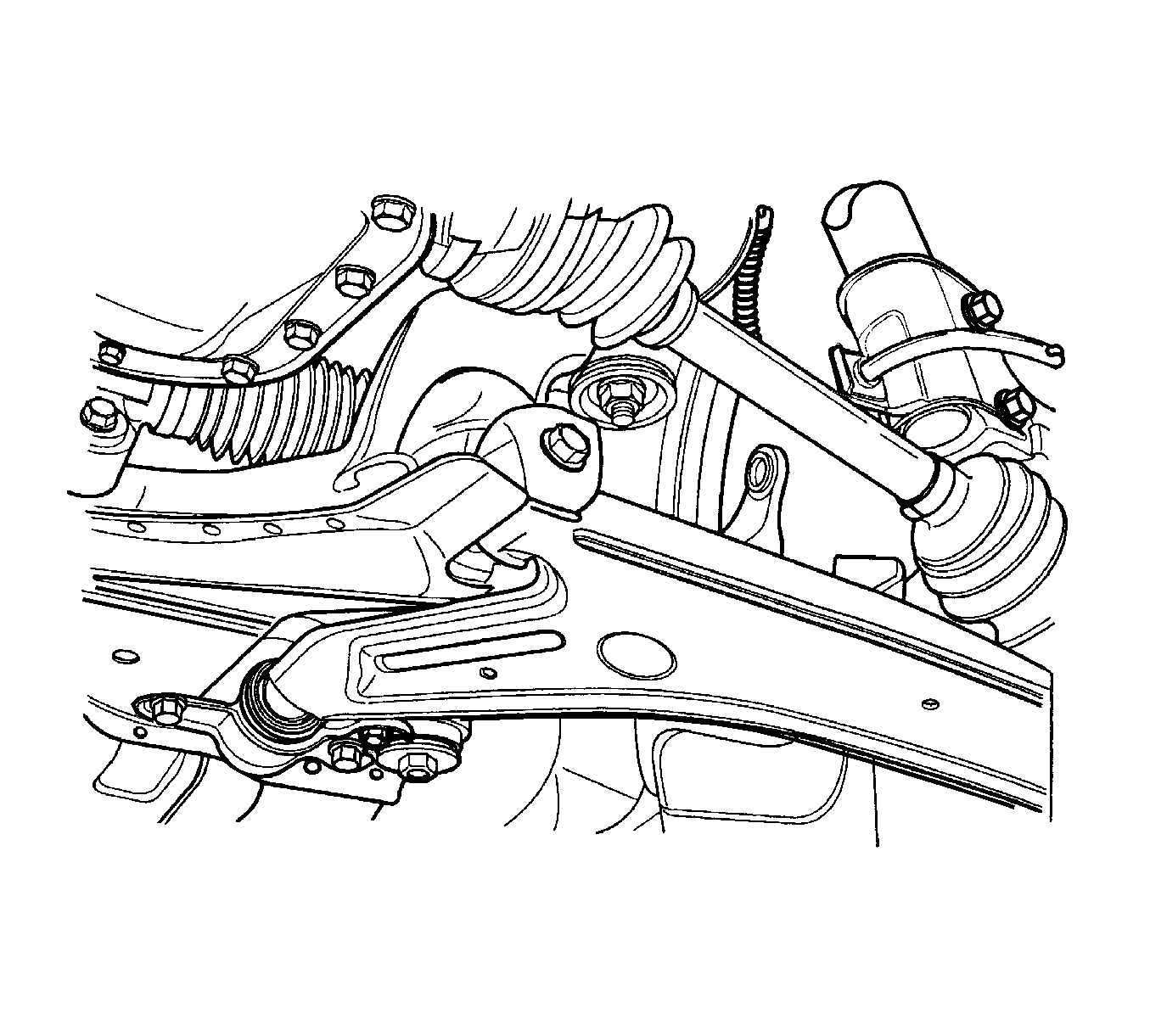
| • | Tighten the control arm bracket bolts to 90 N·m (66 lb ft). |
| • | Tighten the control arm bolt to 180 N·m (133 lb ft). |
