For 1990-2009 cars only
Removal Procedure
- Remove the wheel.
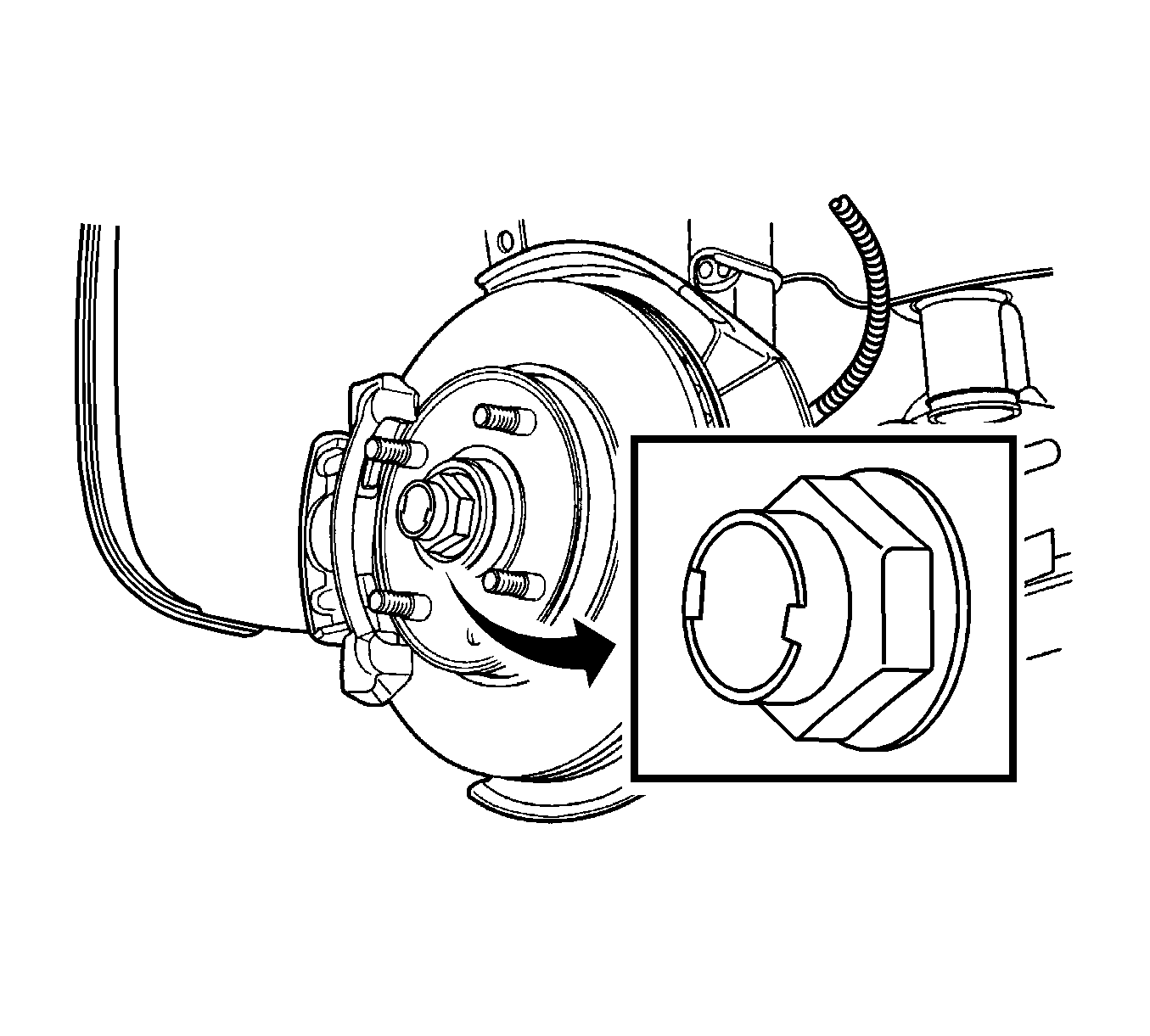
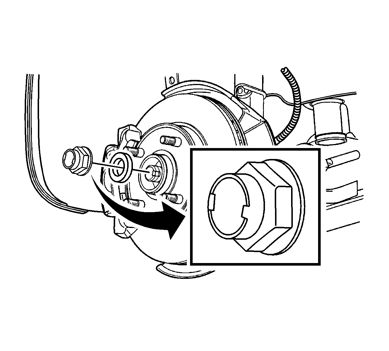
- Remove the caulking nut and washer.
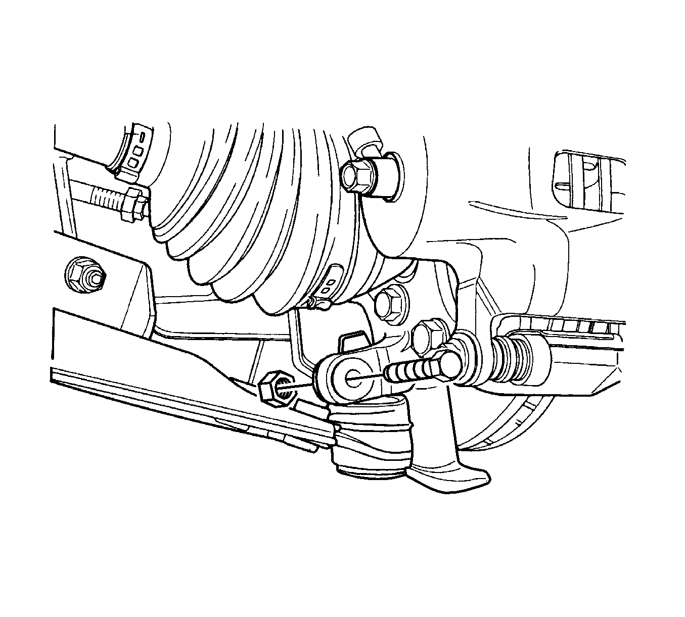
- Remove the outer tie rod. Refer to Steering Linkage Outer Tie Rod Replacement.
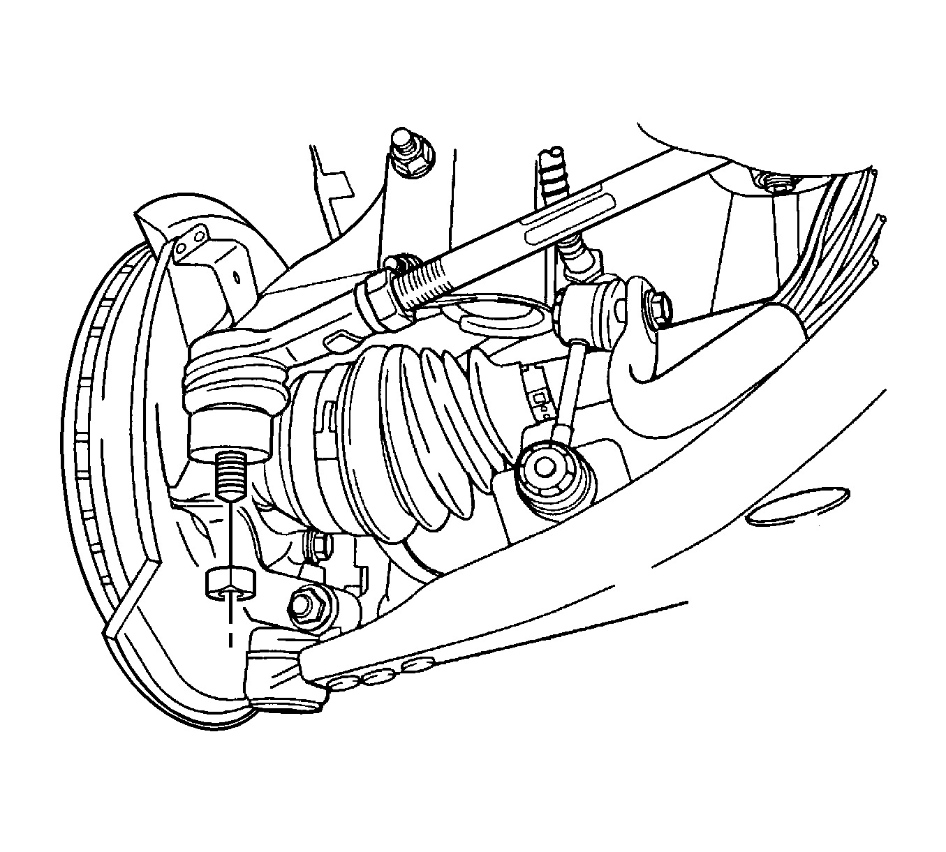
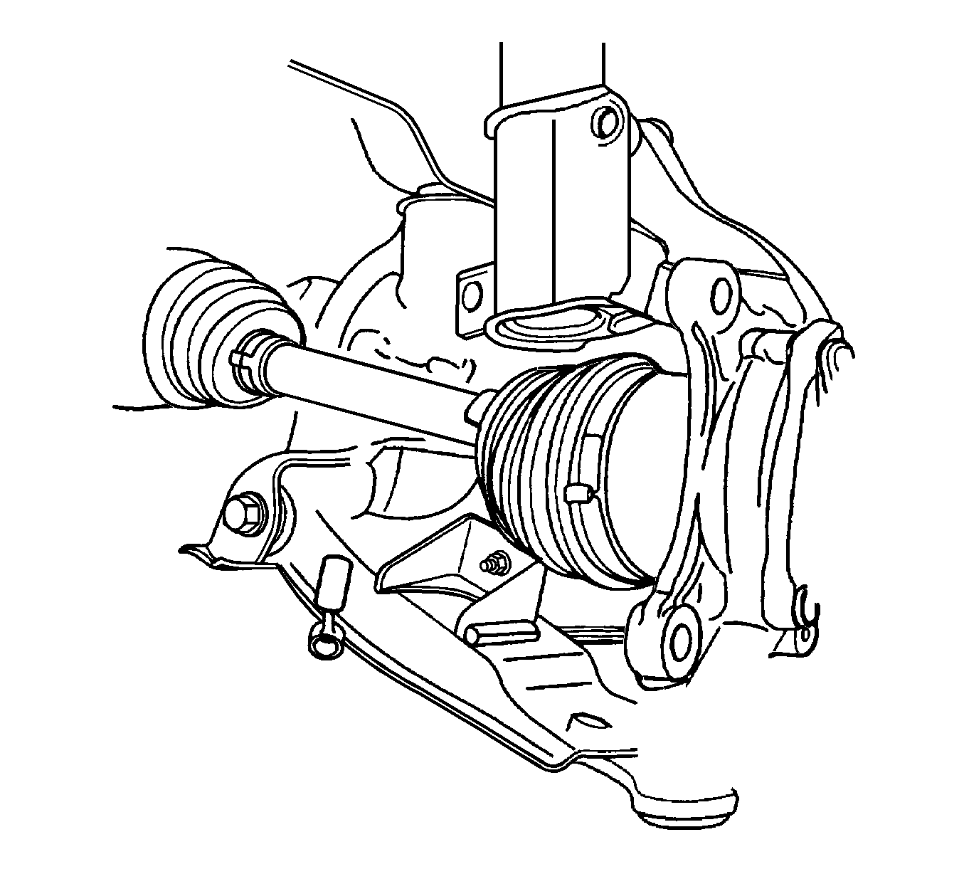
- Disconnect the control arm ball joint.
- Remove the brake caliper. Refer to Front Brake Caliper Replacement.
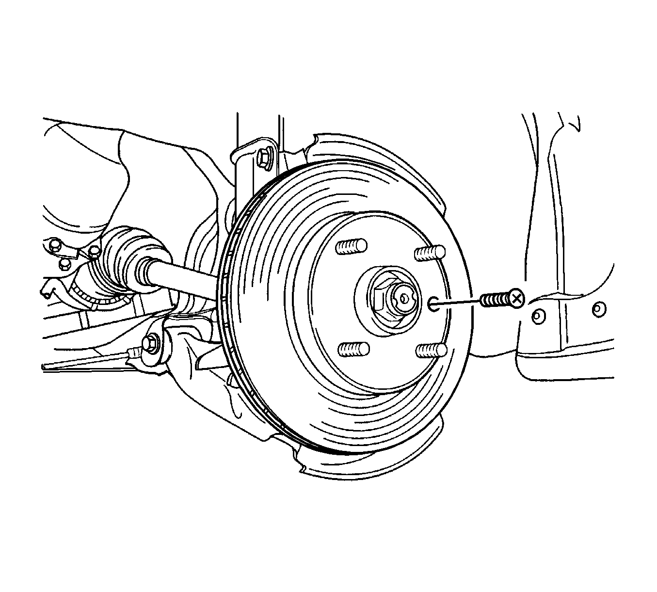
- Remove the detent screw from the brake disc. Remove the disc.
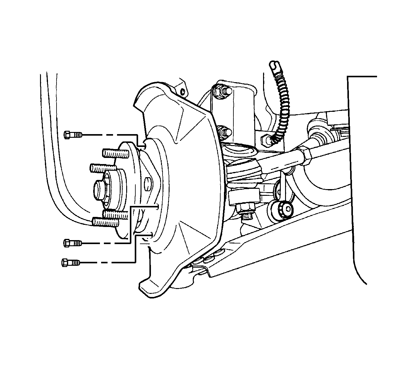
- Remove the splash shield. Refer to Front Brake Shield Replacement.
- Remove the front strut bolts.
- Remove the knuckle, hub assembly.
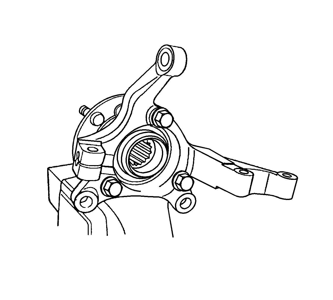
- Remove the hub bolts from the knuckle and separate the hub from the knuckle.
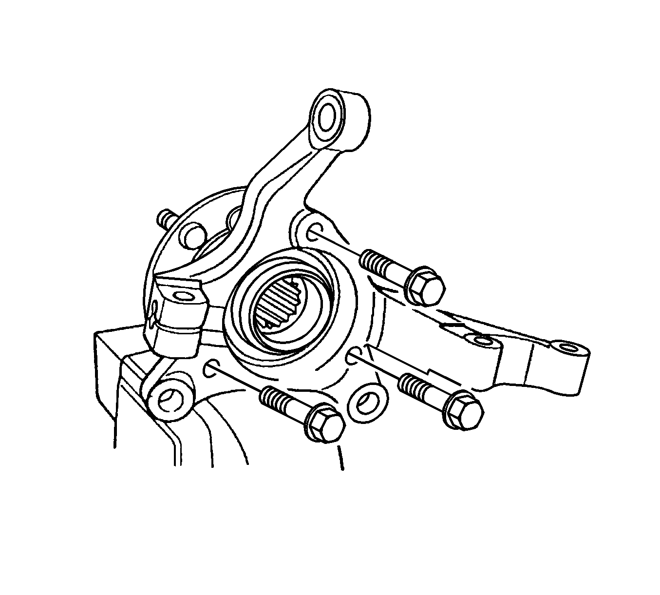
Installation Procedure
- Install the hub bolts and tighten to 95 N·m (70 lb ft).
- Install the splash shield and front strut bolts and tighten to 10 N·m (89 lb in).. Refer to Front Brake Shield Replacement.
- Install the detent screw and disc and tighten to 5 N·m (44 lb in).
- Install the brake caliper. Refer to Front Brake Caliper Replacement.
- Install the control arm ball joint bolt and tighten to 110 N·m (81 lb ft).
- Install the outer tie rod bolt and tighten to 50 N·m (37 lb ft). Refer to Steering Linkage Outer Tie Rod Replacement.
- Install the washer and the caulking nut onto the axle shaft and tighten to 280 N·m (207 lb ft).
- Bleed the air out of the brake system. Refer to Hydraulic Brake System Bleeding.
Caution: Refer to Fastener Caution in the Preface section.
