For 1990-2009 cars only
Special Tools
| • | J 23327 Clutch Spring Compressor |
| • | J 25024-A Servo Piston/Clutch Spring Compressor |
| • | J 28585 Snap Ring Remover |
| • | J 45185 Bore Gage Set |
| • | J 45186 Forward and Direct Clutch Spring Compressor |
- Using J 28585 remove the 4-5 clutch backing plate retaining ring (575) from the 4-5 clutch drum assembly (584).
- Remove the following components from the 4-5 clutch drum assembly (584):
- Remove the 4-5 clutch piston return spring assembly (580).
- Remove the 4-5 clutch piston return spring assembly (580).
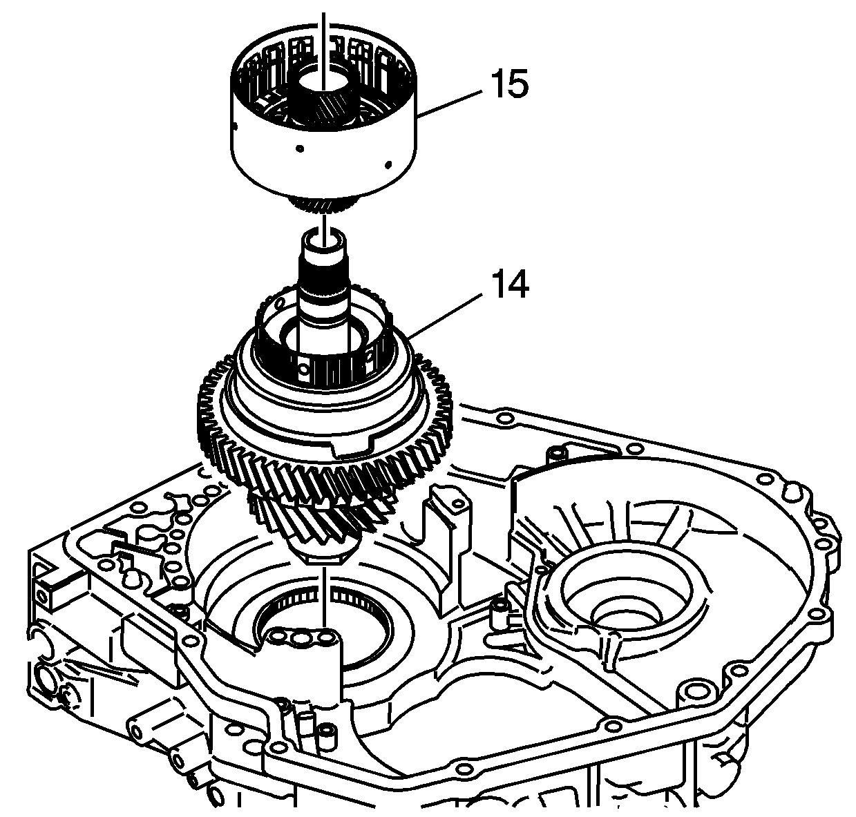
- Using the case as a holding fixture, install the front differential transfer drive gear assembly (14) into the output gear bore.
- Install the 4-5 clutch assembly (15) onto the front differential transfer drive gear assembly (14), with the clutch piston facing up, so that the fluid passages are around the sealing rings.
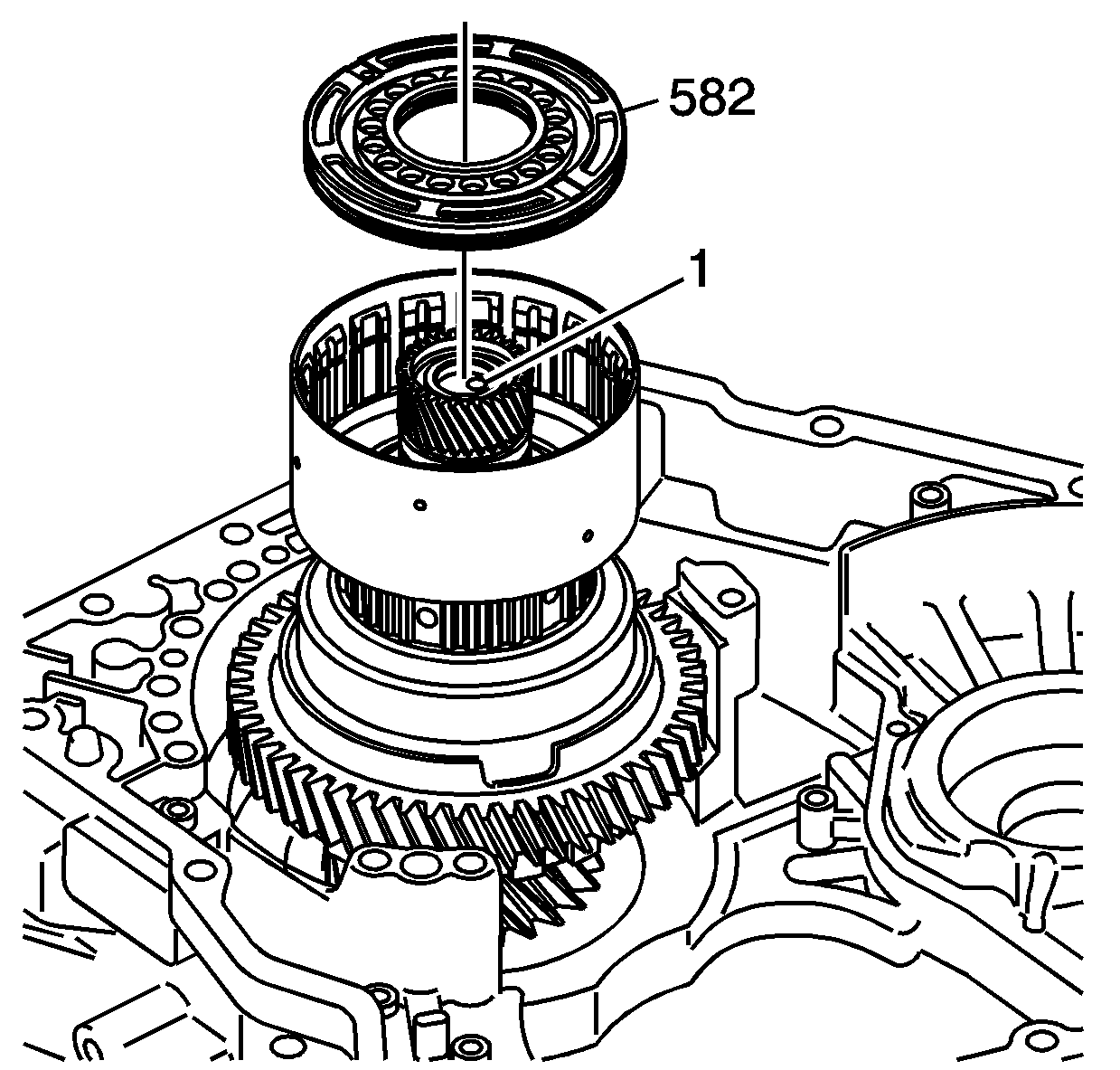
- Apply air pressure to the fluid passage (1) in the end of the front differential transfer drive gear assembly shaft and remove the 4-5 clutch piston assembly (582).
- Remove the 4-5 clutch drum assembly and the front differential transfer drive gear assembly from the case.
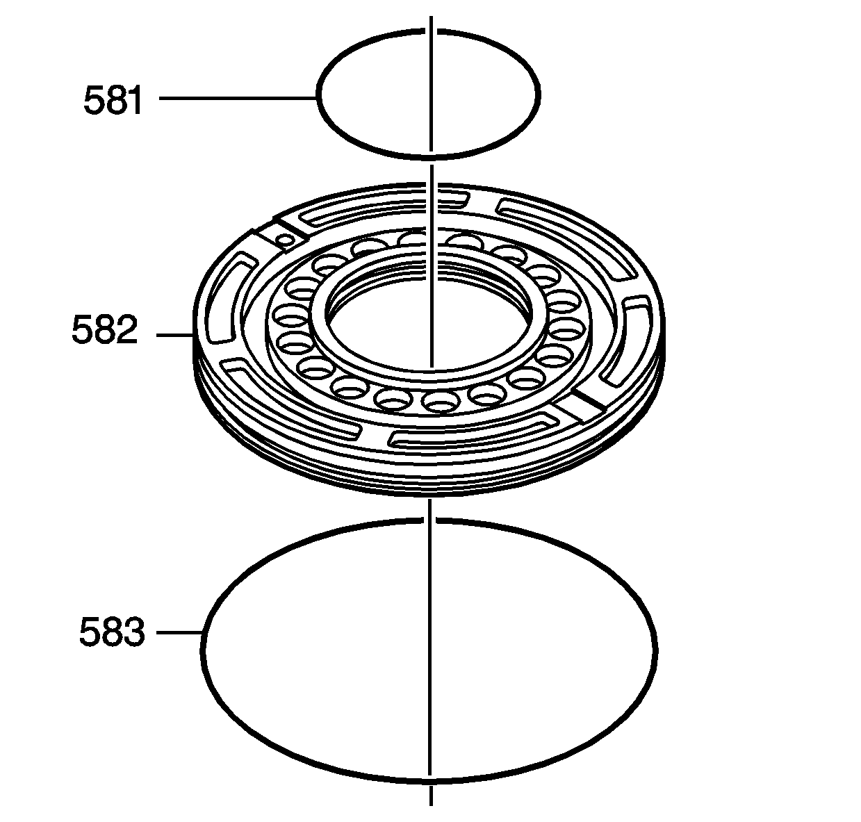
- Remove the piston inner seal (581) and the piston outer seal (583) from the 4-5 clutch piston (582).
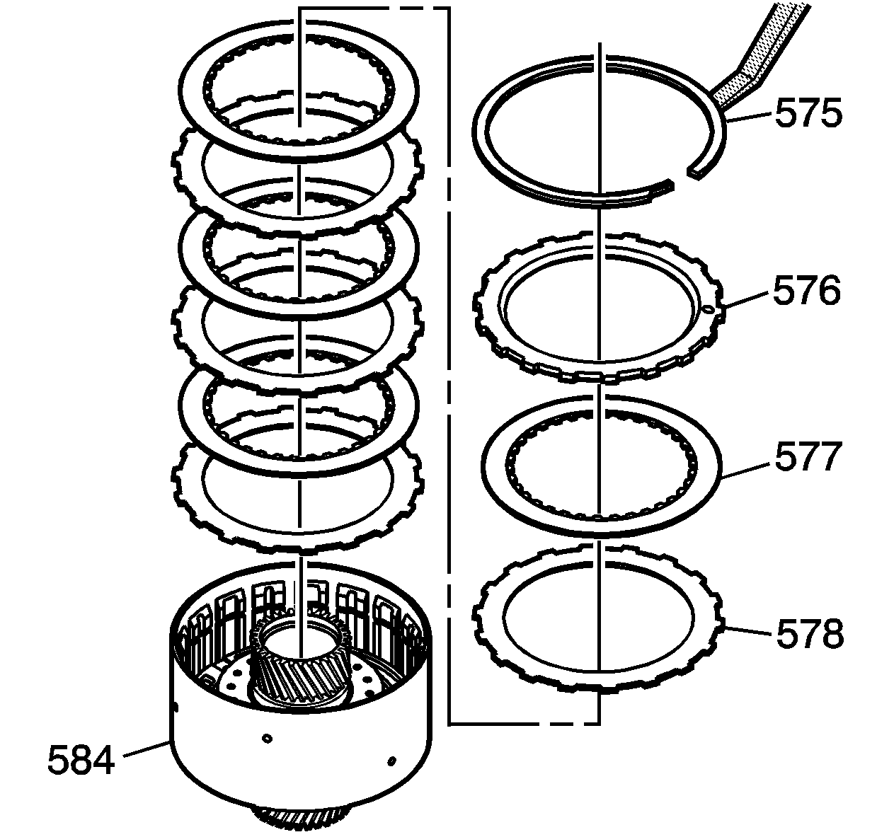
| • | The 4-5 clutch backing plate (576) |
| • | The 4 fiber plates (577) |
| • | The 4 steel plates (578) |
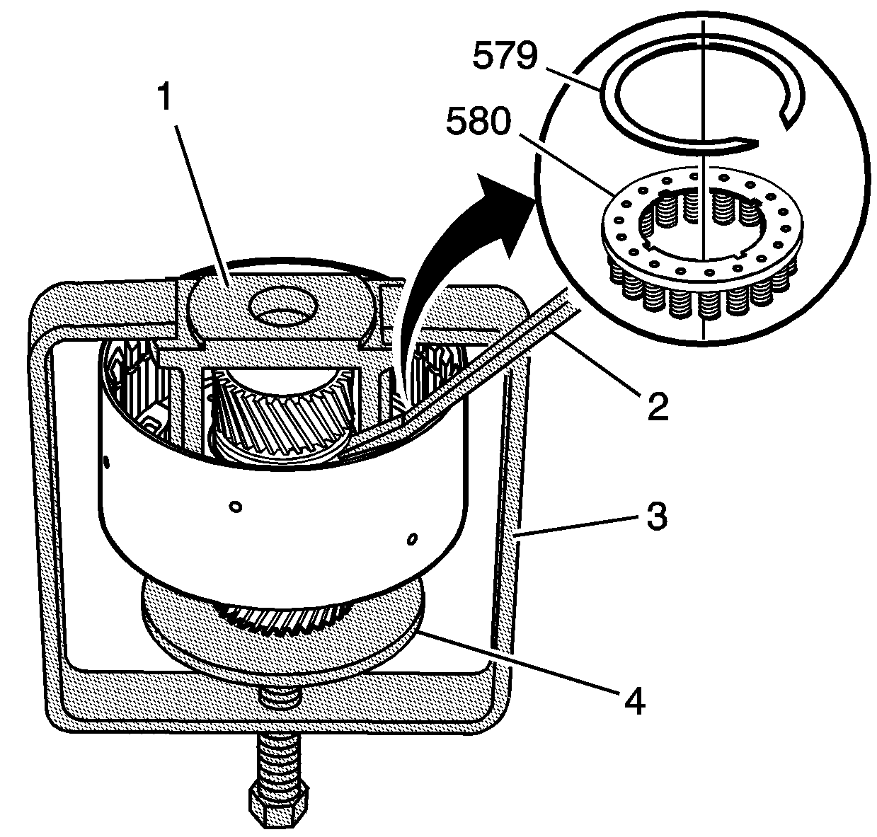
| 3.1. | Place the J 25024-A (3) in a vise with the forcing screw on the bottom and backed out. |
| 3.2. | Place the J 45186 (1) on the 4-5 clutch piston return spring assembly (580). |
| 3.4. | Place the clutch housing with the J 45186 (1) on the J 21420-2 (4) and under the arms of J 25024-A (3). |
| 3.5. | With the forcing screw, compress the clutch spring to allow the removal of the retaining ring. |
| 3.6. | Use J 28585 (2) or snap ring pliers to remove the retaining ring (579). |
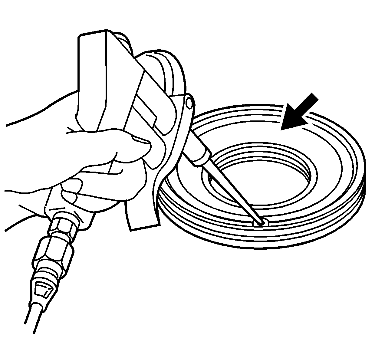
Warning: Wear safety glasses when using compressed air in order to prevent eye injury.
Clean and Inspection
- Wash the clutch components in clean solvent and air dry.
- Inspect the clutch drum for the following conditions:
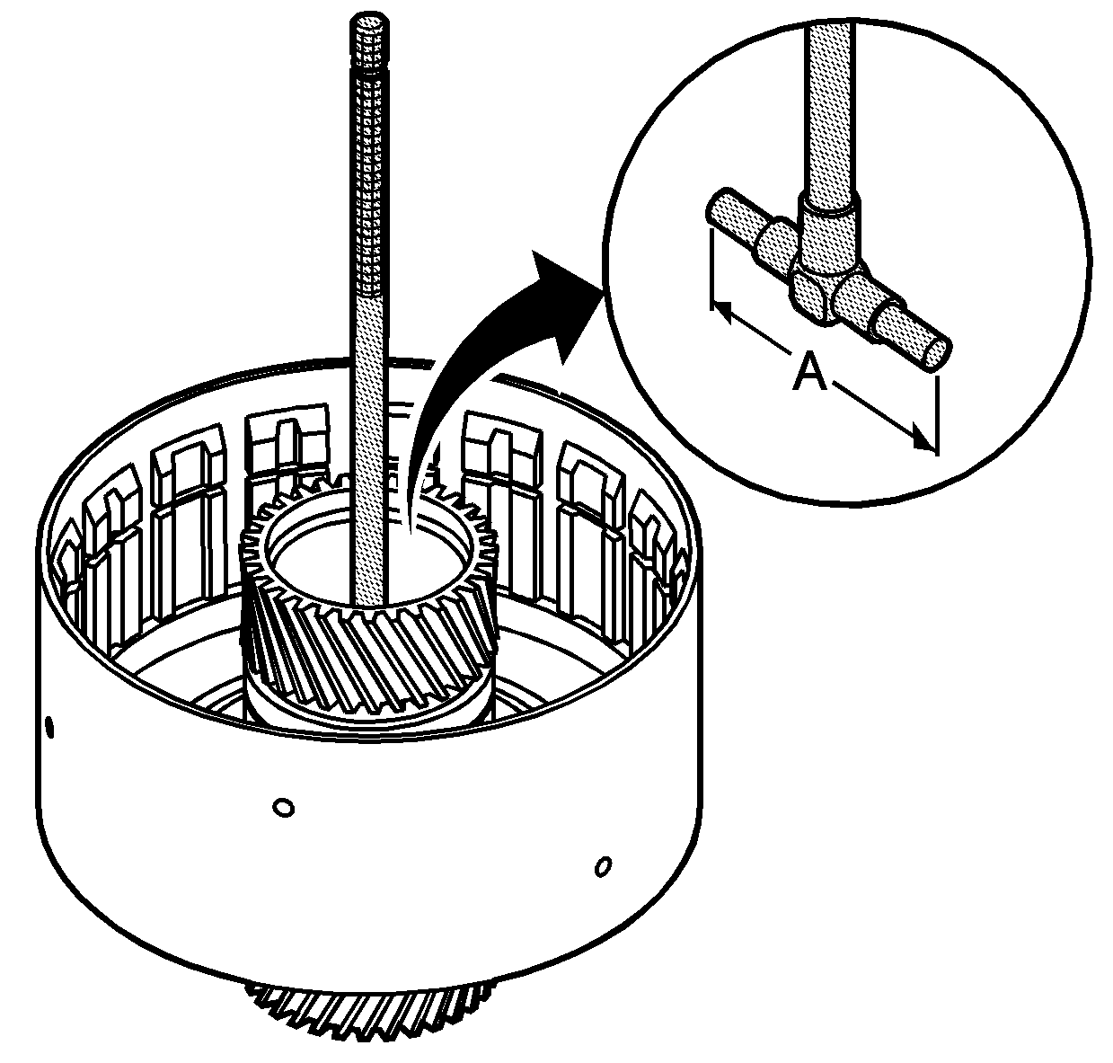
- Using J 45185 , measure the inner diameter of the 4-5 clutch drum bushing (A) at different locations and take the average.
- If the bushing is out of specifications or any of the above conditions are found replace the 4-5 clutch drum.
- Shake the clutch piston to inspect the ball check valve for not being stuck.
- Apply compressed air in the opposite side of the check valve and inspect for leaking.
- Inspect the piston O-ring seal grooves for damage.
- Replace the piston if any of the above conditions are found.
- Inspect the clutch plates and discs for wear, warp age, or being burnt.
- Replace the clutch plates and discs if any of the above conditions are found.
| • | Lugs in the drum for excessive grooves that prevent the clutch plates from sliding |
| • | Sun gear for chips or metal embedded in the teeth |
| • | Drum surface for scoring or excessive wear |
| • | Piston O-ring surfaces for wear, nicks, or scratches |
| • | Bearing thrust surfaces for damage or wear |
Specification
36.125-36.200 mm (1.422-1.425 in)
