Tools Required
6297 Ball Joint Release Tool.
Removal Procedure
- Raise and support the vehicle. Refer to Lifting and Jacking the Vehicle.
- Remove the front wheel. Refer to Tire and Wheel Removal and Installation.
- Remove the stabiliser bar link to stabiliser bar retaining nut (1) from both sides of the stabiliser bar.
- Disconnect the stabiliser bar link (2) from the stabiliser bar (3) from both sides of the stabiliser bar.
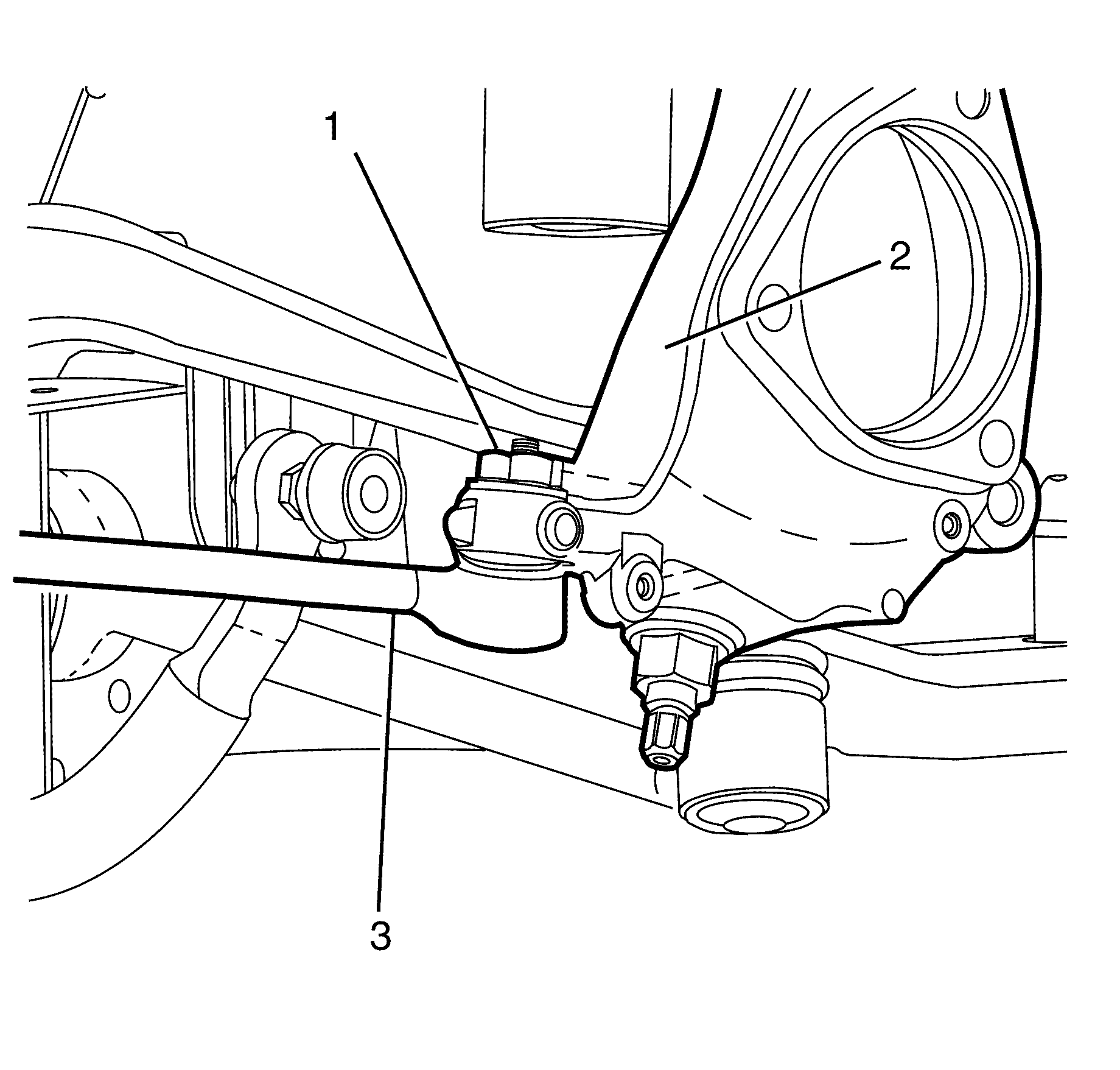
- Remove the tie rod end ball joint to steering knuckle retaining nut (1) on both sides of the vehicle.
- Disconnect the tie rod (3) from the steering knuckle (2) using the 6297 (1) on both sides of the vehicle.
- Remove the mass air flow (MAF) sensor. Refer to Mass Airflow Sensor/Intake Air Temperature Sensor Replacement for 3.6L engine or Mass Airflow Sensor/Intake Air Temperature Sensor Replacement for 6.0L engine.
- Remove the upper section of the air box. Refer to Air Cleaner Assembly Replacement for 3.6L engine or Air Cleaner Assembly Replacement for 6.0L engine.
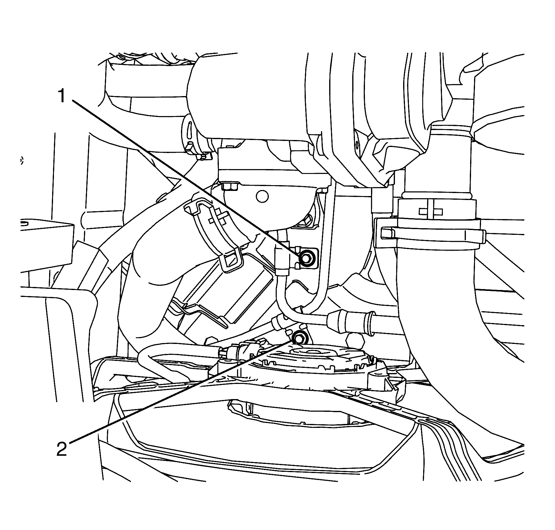
- Remove the power steering gear inlet pipe/hose bracket to subframe retaining bolt (2).
- Remove the power steering gear outlet pipe/hose bracket to subframe retaining bolt (1).
- Remove the stabliser bar insulators from the stabiliser bar. Refer to Stabilizer Shaft Insulator Replacement .
- Remove the stabiliser bar from the vehicle.
Caution: Refer to Safety Glasses Caution in the Preface section.
Caution: Refer to Vehicle Lifting Caution in the Preface section.
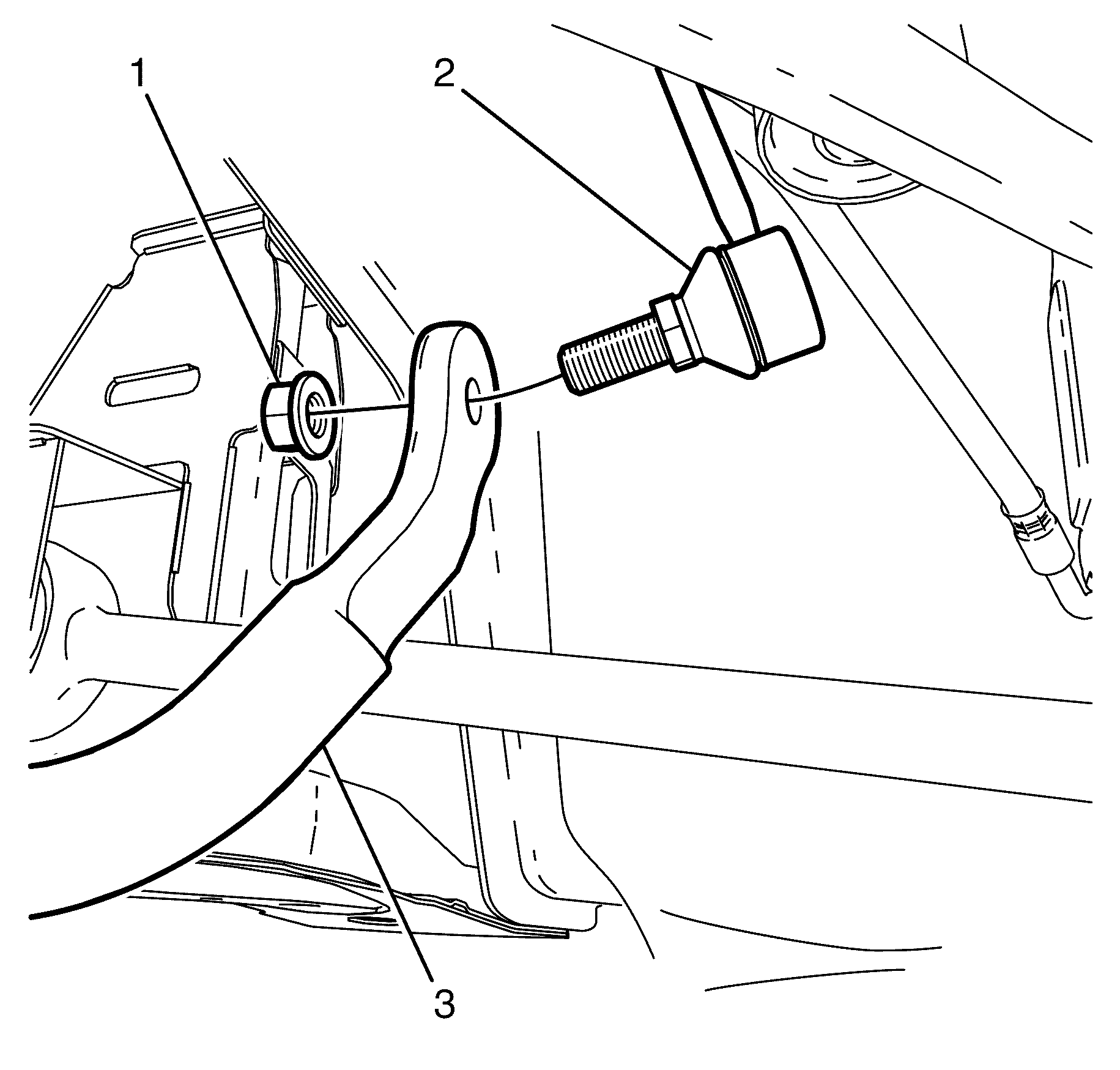
Important: Nuts with micro-encapsulated thread sealant must be discarded after removal.
Discard the nuts.
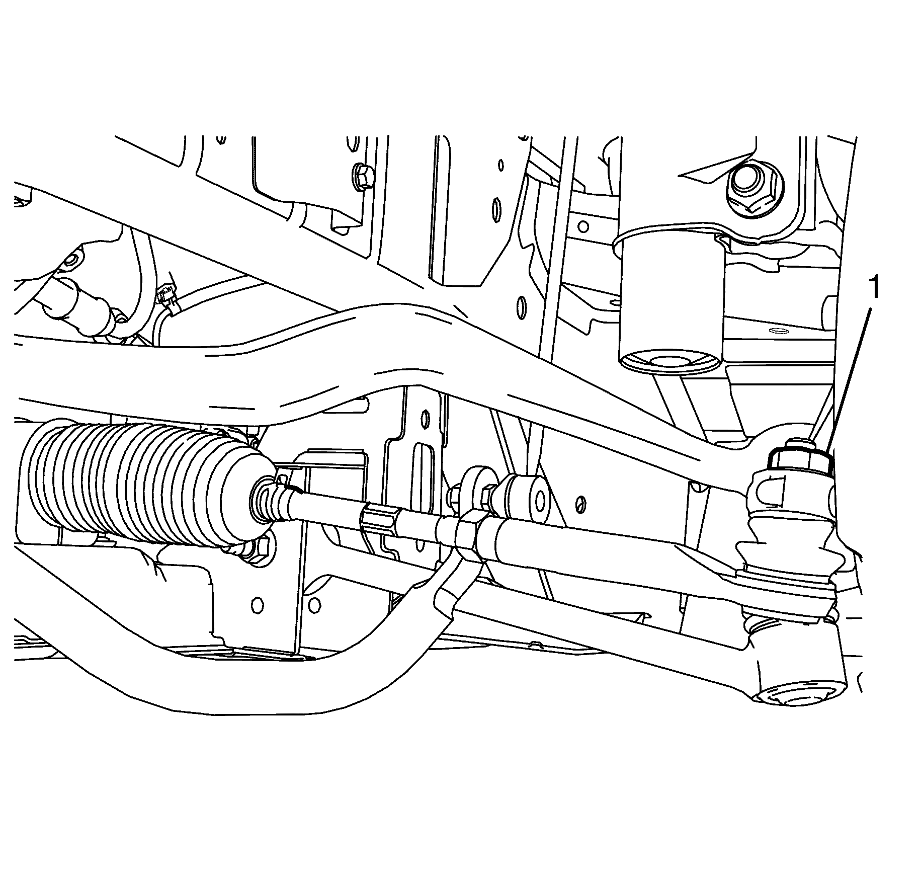
Important: Nuts with micro-encapsulated thread sealant must be discarded after removal.
Discard the nuts.
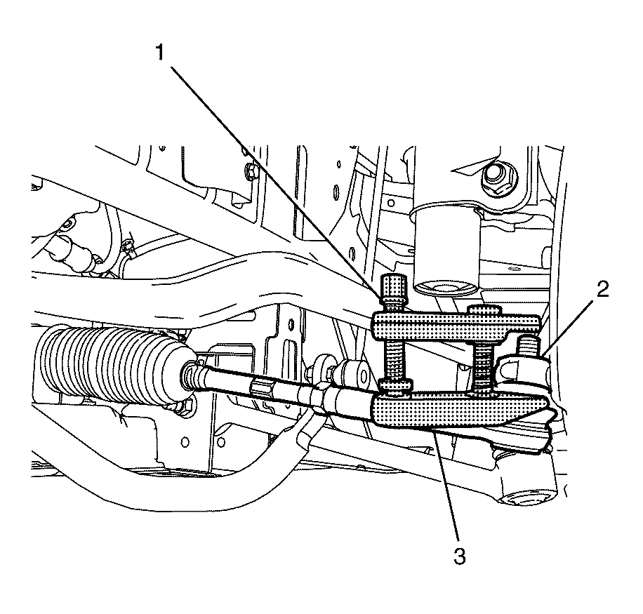
Important: Once a load is applied by the ball joint release tool loading bolt, a quick tap on the nut end of the tool will reduce the separating force required.
Installation Procedure
- Install the stabiliser bar to the vehicle.
- Install the stabiliser bar insulators. Refer to Stabilizer Shaft Insulator Replacement .
- Install the mass air flow (MAF) sensor. Refer to Mass Airflow Sensor/Intake Air Temperature Sensor Replacement for 3.6L engine or Mass Airflow Sensor/Intake Air Temperature Sensor Replacement for 6.0L engine.
- Install the upper section of the air box. Refer to Air Cleaner Assembly Replacement for 3.6L engine or Air Cleaner Assembly Replacement for 6.0L engine.
- Remove the power steering gear inlet pipe/hose bracket to subframe retaining bolt (2).
- Remove the power steering gear outlet pipe/hose bracket to subframe retaining bolt (1).
- Install the stabiliser bar link (2) to the stabiliser bar (3) to both sides of the vehicle.
- Install the NEW stabiliser bar link to stabiliser bar retaining nut (1) to both sides of the vehicle.
- Install the tie rod (3) to the steering knuckle (2) on both sides of the vehicle.
- Install the NEW tie rod to steering knuckle retaining nut (1) on both sides of the vehicle.
- Install the front wheel. Refer to Tire and Wheel Removal and Installation .
- Remove the safety stands.
- Lower the vehicle to the ground.
Notice: Refer to Fastener Tightening Specifications in the Preface section.
Notice: Refer to Fastener Notice in the Preface section.

Tighten
Tighten the bolt to 9 N·m (80 lb in).
Tighten
Tighten the bolt to 9 N·m (80 lb ft).

Tighten
Tighten the nut to 50 N·m (37 lb ft).
Tighten
Tighten the nut to 70 N·m (52 lb ft).
