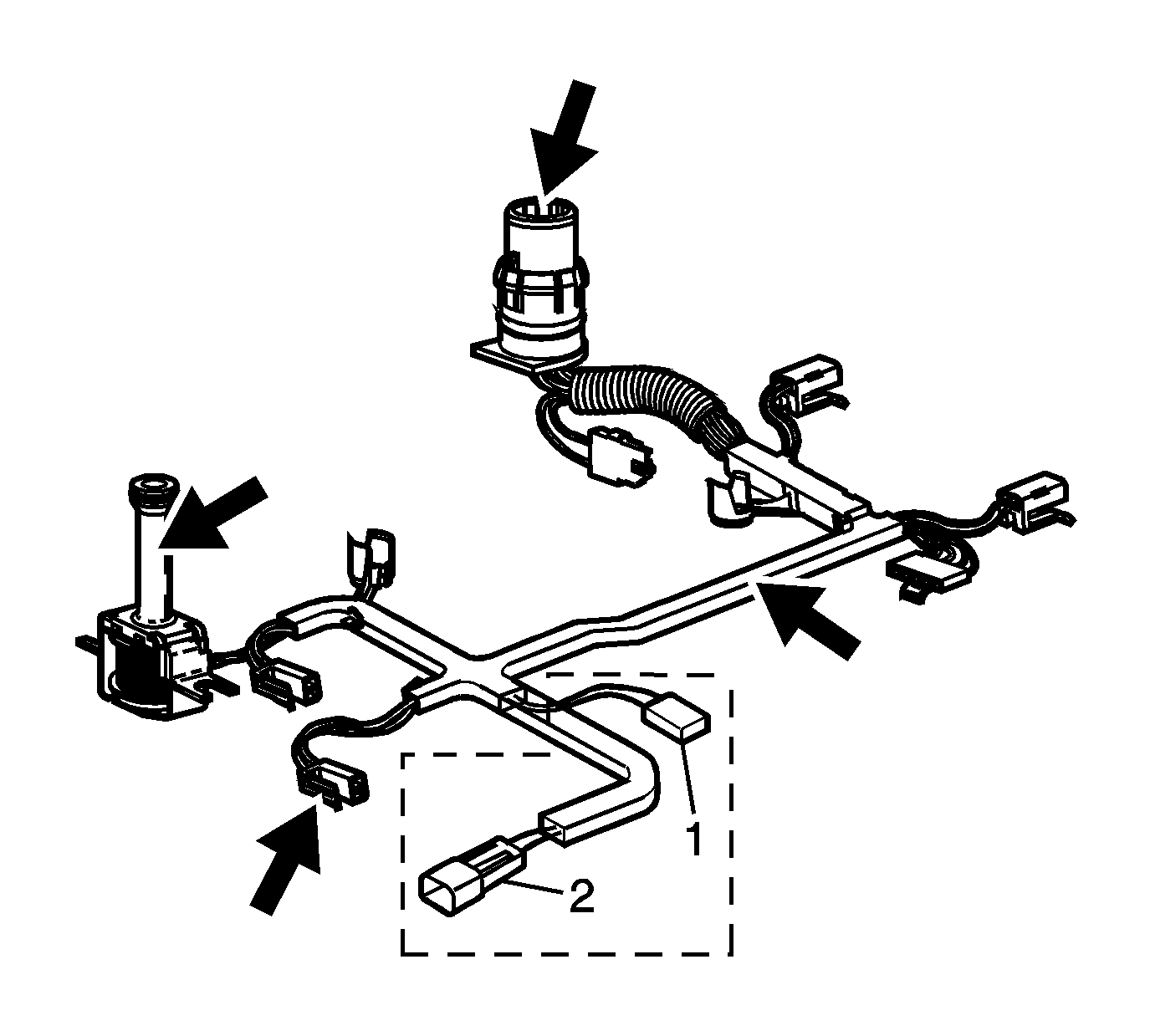
Important: Secondary fluid pump connector (1)
is used for M33 models only, connector (2) is used on ISS models.
- Inspect the wiring harness and solenoid assembly for the following conditions:
| • | Loose electrical terminals |
| • | Damaged wiring loom and conduit |
| • | Worn, missing, or cut pass-through connector O-ring seal. |
- Install the transmission wiring harness pass-through connector into the
transmission case. Ensure connector tabs lock into place.
- Move the harness to one side in order to install the valve body.
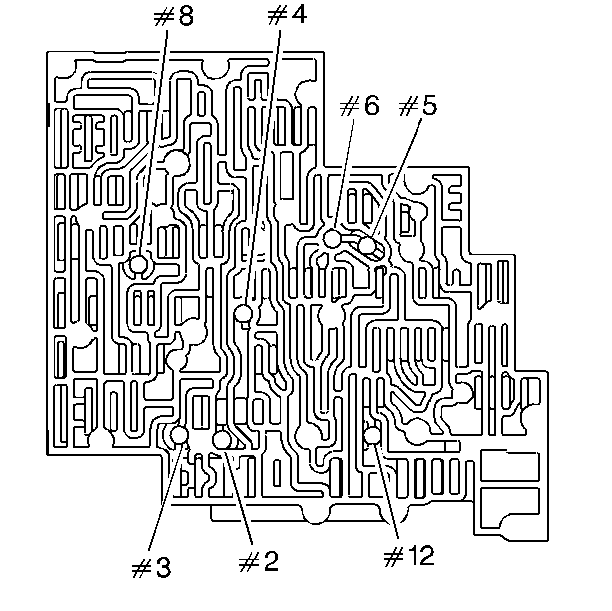
Important: Valve bodies are model dependent.
Important: Some models do not use a #5 ball check valve.
- Install the ball check valves (2-6, 8, 12) in the valve body and
retain ball check valves with
J 36850 or an equivalent.
Notice: Refer to General Repair Instructions in the Preface section.
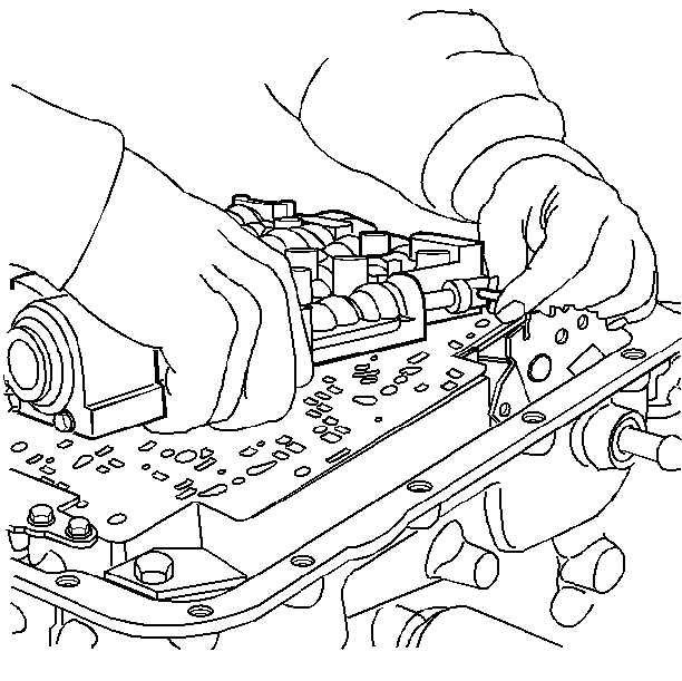
- Install the valve body over the
J 25025-5 ,
and connect the manual valve link to the manual valve.
- Install two valve body retaining bolts (62) to hold the valve body
in place.
- Remove the
J 25025-5 .
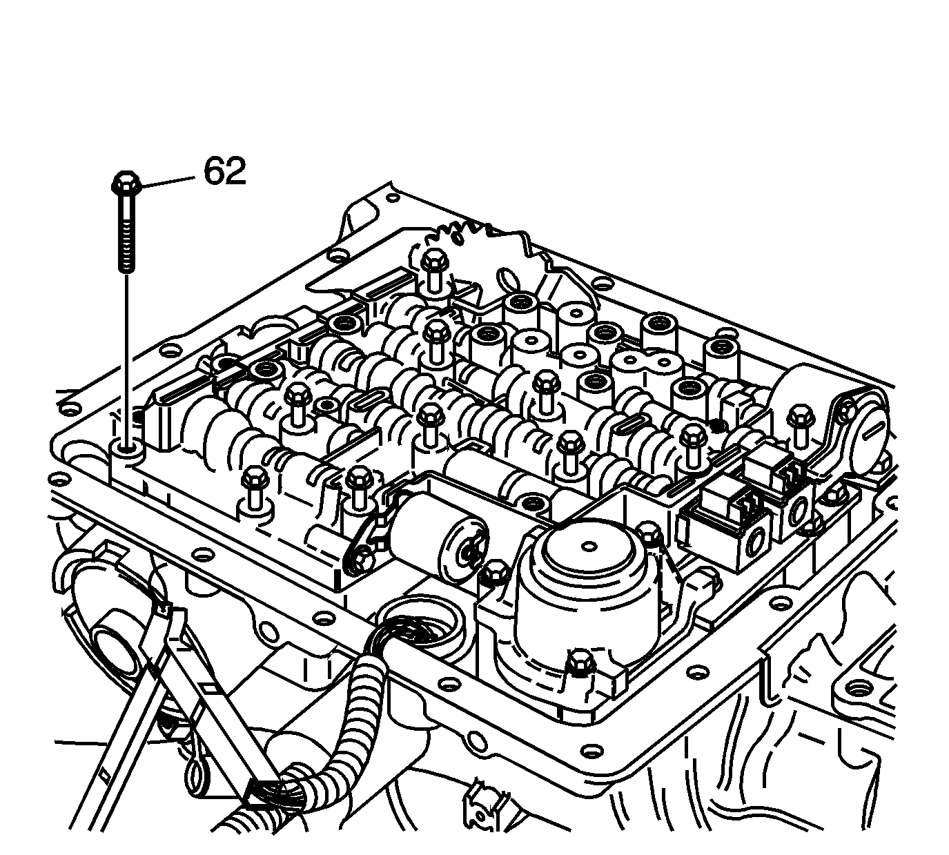
- Install the valve body bolts (62) that are
shown only.
- Finger tighten the bolts.
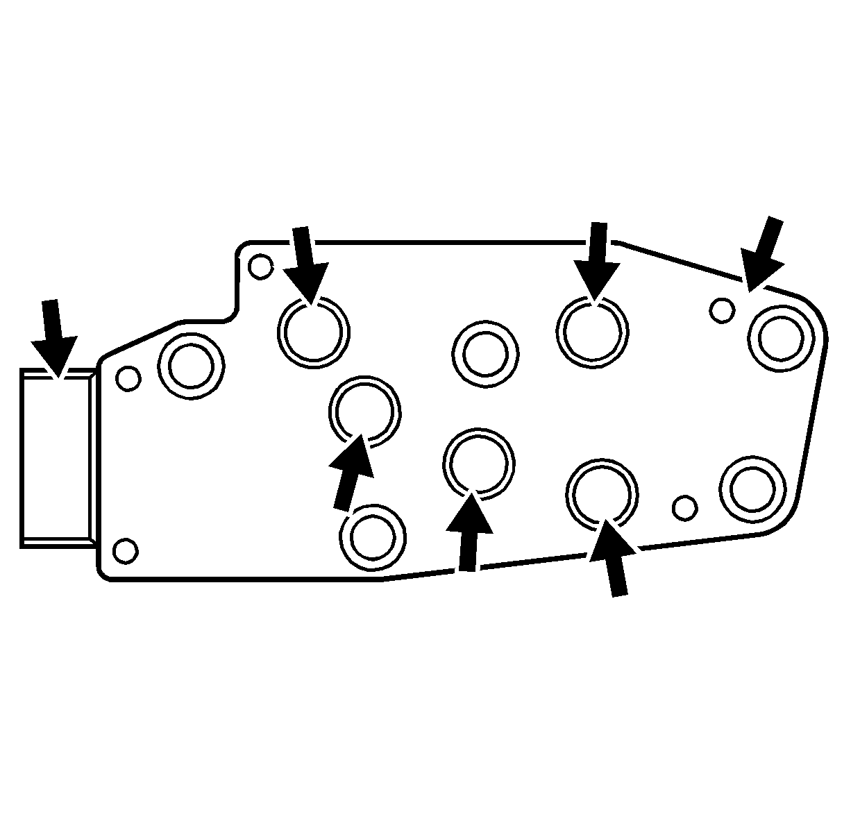
- Inspect the Transmission Fluid Pressure (TFP) Manual
Valve Position Switch Assembly for the following conditions:
| • | Damaged or missing O-rings |
| • | Loose electrical terminals |
| • | Poor terminal retention |
| • | Sediment in switch membrane |
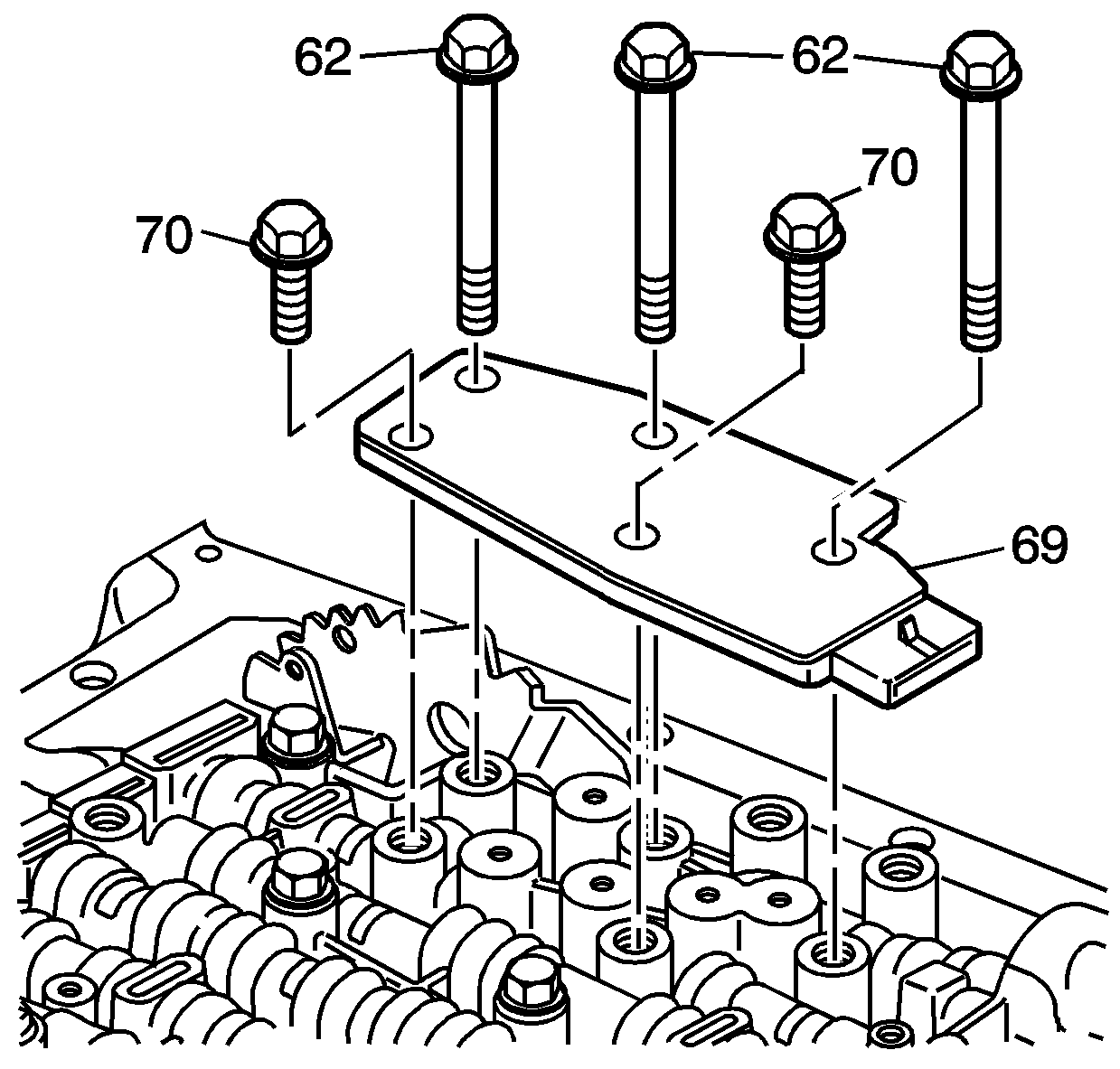
- Install the TFP manual valve position switch (69)
and retaining bolts (62, 70).
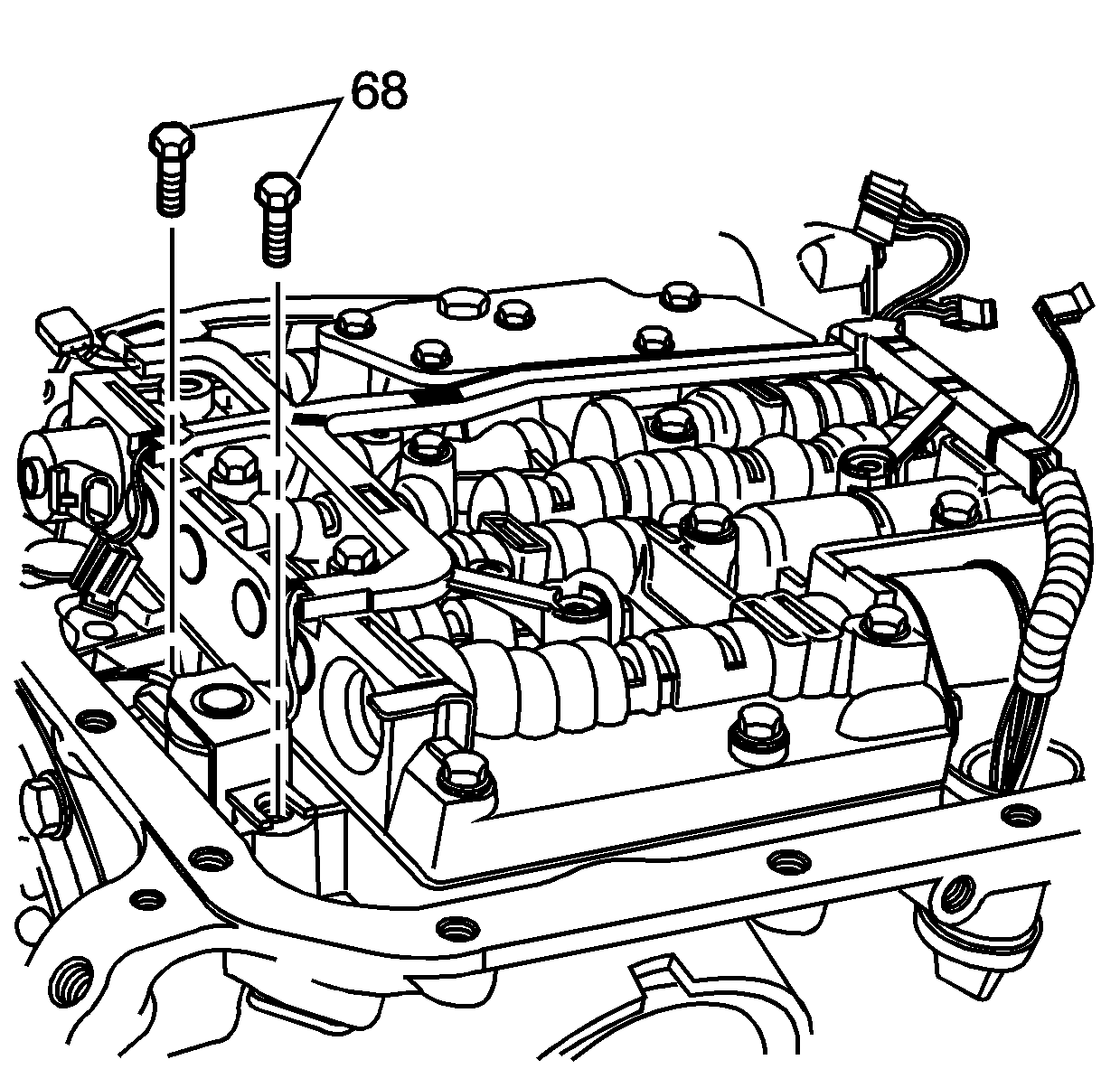
- Install the transmission wiring harness on the valve
body.
Notice: Refer to Fastener Notice in the Preface section.
- Install the TCC solenoid valve and retaining bolts (68).
Tighten
Tighten the bolts to 8-14 N·m
(6-10 lb ft).
Notice: Refer to General Repair Instructions in the Preface section.
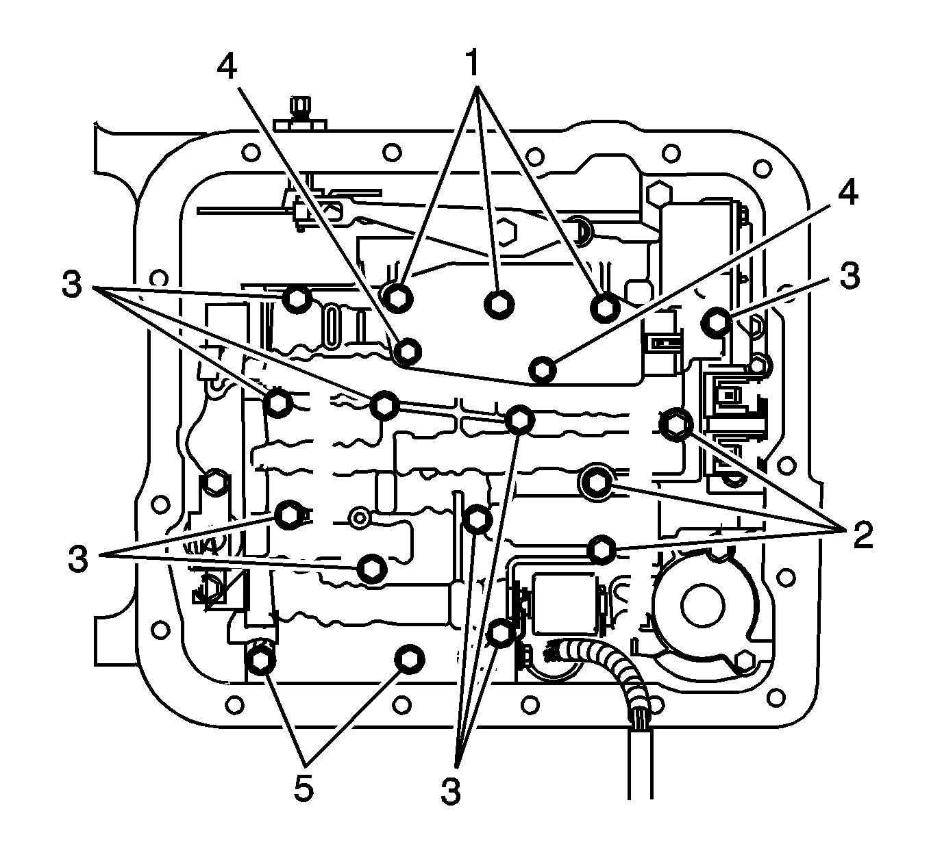
- Check that all the valve body retaining bolts are in the correct location.
Each bolt number refers to a specific bolt size, as indicated by the following
list:
- Tighten the retaining bolts from the center of the valve body working
your way out in a spiral pattern to the outside edge.
Tighten
Tighten the retaining bolts to 8-14 N·m
(6-10 lb ft).
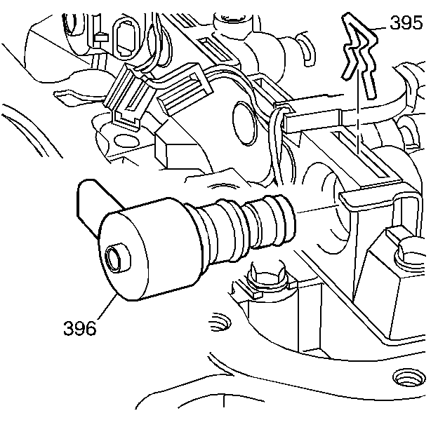
- Install the TCC PWM solenoid valve (396)
and the solenoid retainer (395).
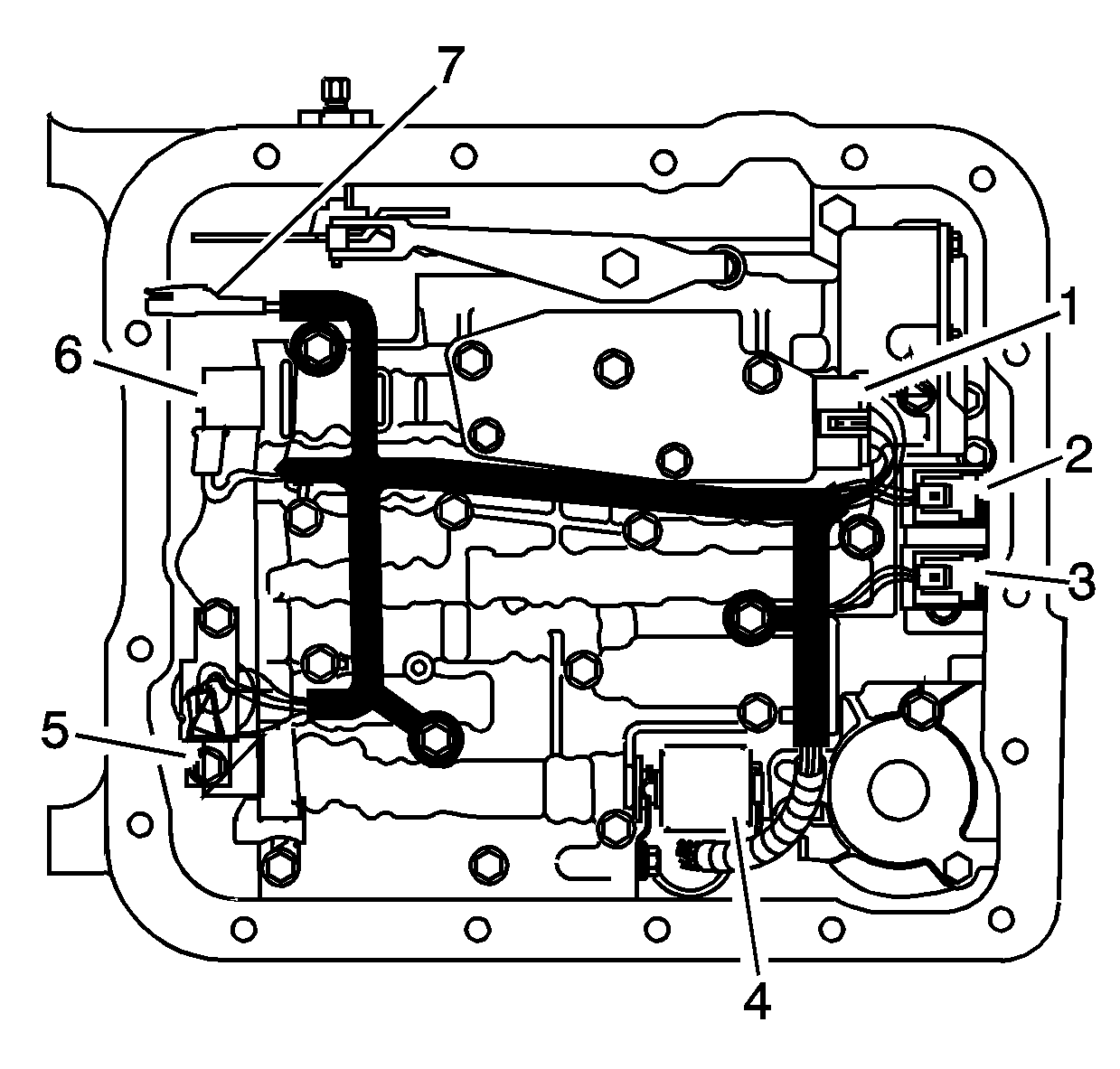
- Snap the wiring harness in place on the valve body
bolts. Ensure the harness loom tab is located under the TFP switch.
- Install the wiring connectors to the electrical components as indicated
by the following list:
| • | 1 - Transmission Fluid Pressure (TFP) manual
valve position switch |
| • | 4 - Pressure Control Solenoid (PCS) |
| • | 5 - Torque Converter Clutch Pulse Width Modulation (TCC PWM)
Solenoid |
| • | 7 - Input speed sensor (ISS) - model
dependent |


