Clutch Assembly Replacement 3.6L Engine
Removal Procedure
- Disable the SIR system. Refer to SIR Disabling and Enabling.
- Disconnect the battery ground cable from the battery. Refer to Battery Negative Cable Disconnection and Connection.
- Raise and support the vehicle. Refer to Lifting and Jacking the Vehicle.
- Remove the transmission assembly. Refer to Transmission Replacement.
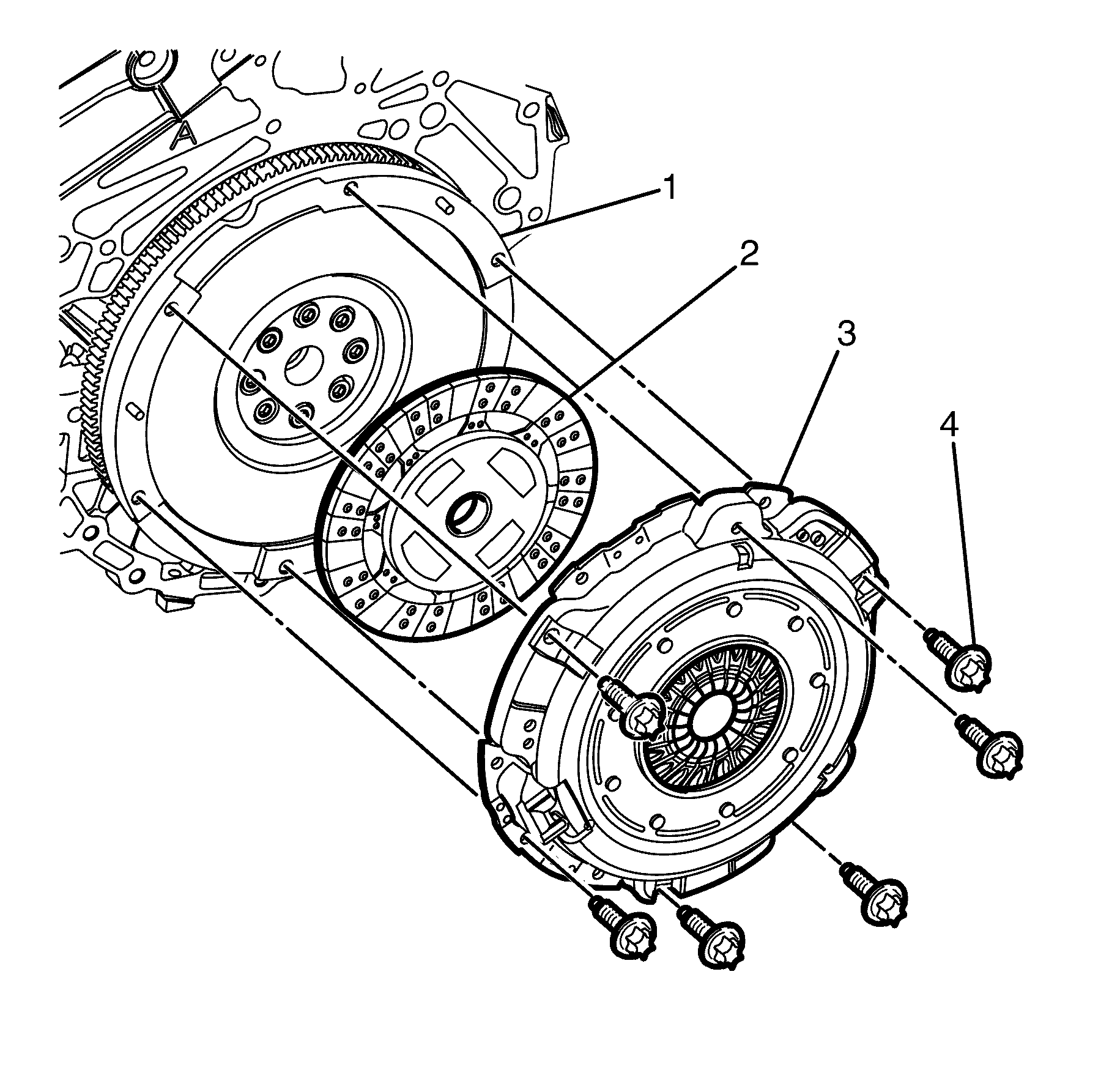
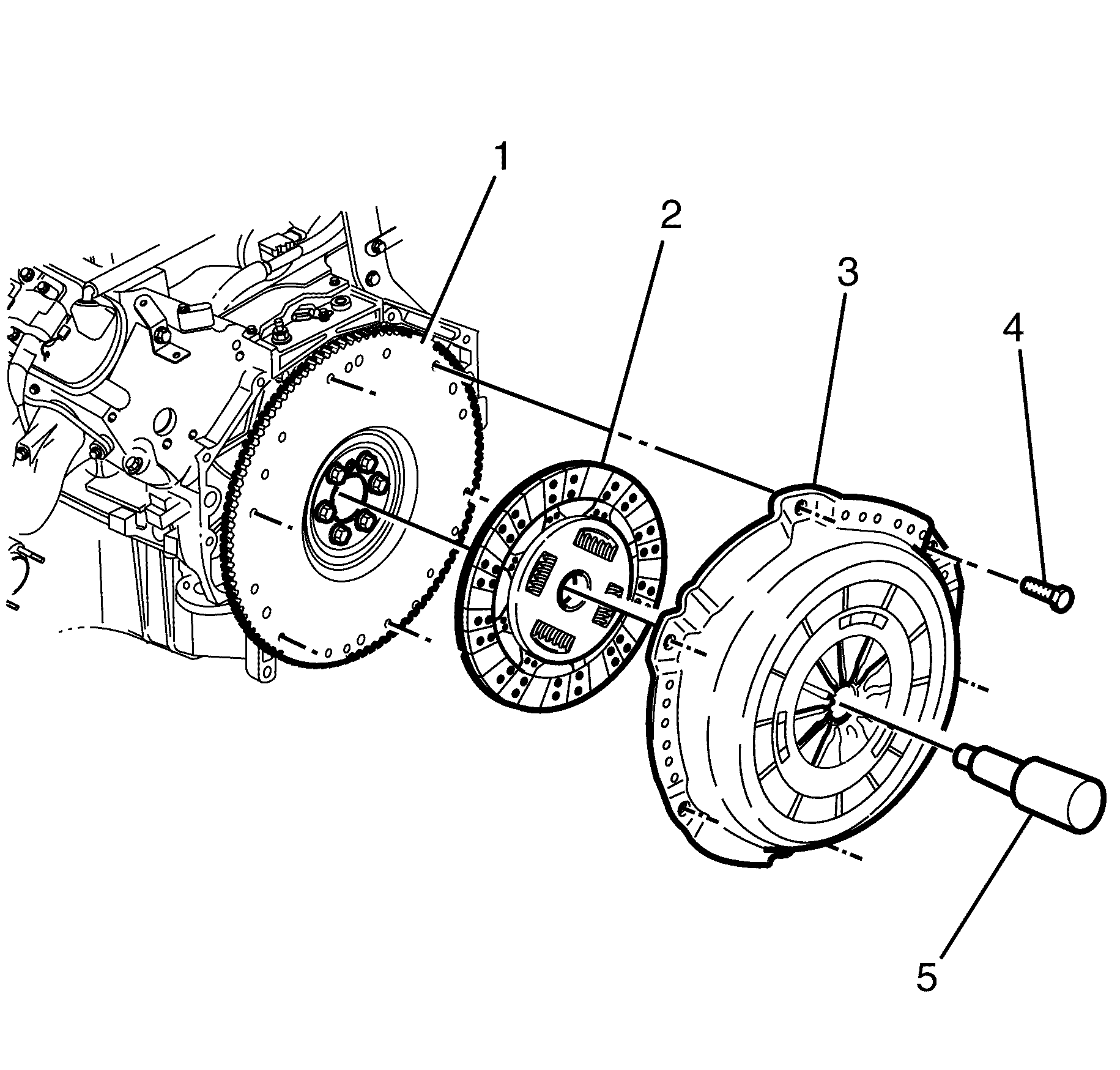
- Mark the relationship of the pressure plate (3) to the flywheel (1) to maintain the correct balance condition on reassembly.
- Loosen all pressure plate to flywheel retaining bolts (4) working from opposite sides to avoid distortion.
- Continue loosening pressure plate to flywheel retaining bolts (4) from opposite sides until all are removed.
- Remove the pressure plate (3) and clutch driven plate (2) from the flywheel (1).
Caution: Refer to Battery Disconnect Caution in the Preface section.
Caution: Refer to Safety Glasses Caution in the Preface section.
Caution: Refer to Vehicle Lifting Caution in the Preface section.
Installation Procedure
- While holding the pressure plate (3), and clutch driven plate (2), together, align them to the flywheel (1).
- Install the pressure plate to flywheel retaining bolts (4).
- Using a universal clutch driven plate centering tool (5) align the clutch driven plate (2) to the flywheel (1).
- Tighten the pressure plate to flywheel retaining bolts, using the sequence shown.
- Tighten the flywheel.
- Remove the clutch driven plate centering tool.
- Install the transmission assembly. Refer to Transmission Replacement.
- Inspect lubricant level in transmission, adjust as necessary. Refer to General Specifications.
- Bleed the clutch hydraulic system. Refer to Hydraulic Clutch Bleeding.
- Connect the battery ground cable from the battery. Refer to Battery Negative Cable Disconnection and Connection.
- Enable the SIR. Refer to SIR Disabling and Enabling.
- Road test vehicle for correct clutch operation.
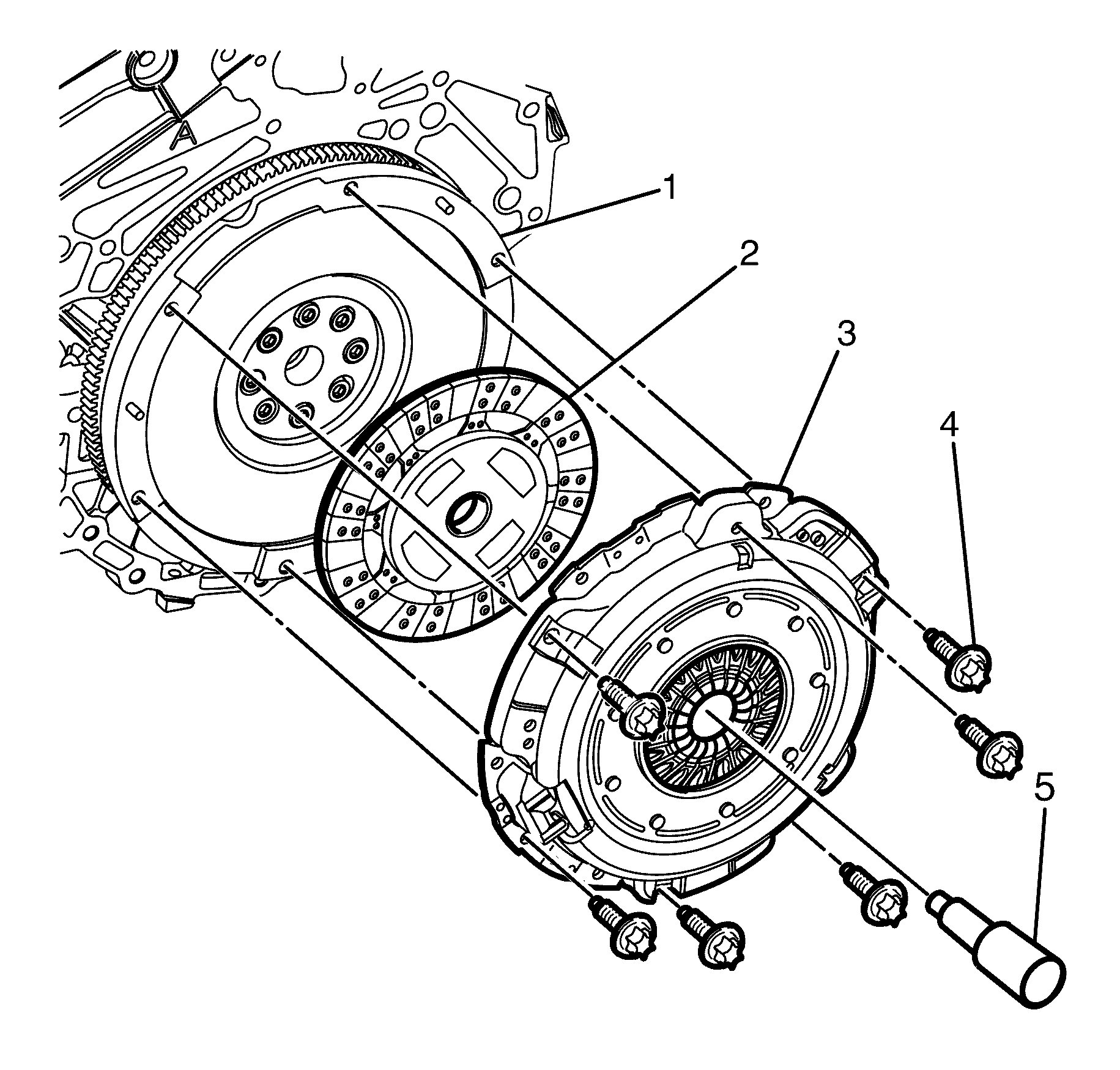
Important: Do Not apply any lubricant to clutch driven plate splines if lubricant is applied premature failure could result.
Important: Install the clutch driven plate (2) with the short boss facing the flywheel (1). Flywheel side is stamped on the clutch driven plate hub (FW Side).
Important: The pressure plate to flywheel retaining bolts (4) must not to be fully tightened at this stage.
Do Not tighten at this stage.
Notice: Refer to General Repair Instructions in the Preface section.
Notice: Refer to General Repair Instructions in the Preface section.
Notice: Refer to Fastener Notice in the Preface section.
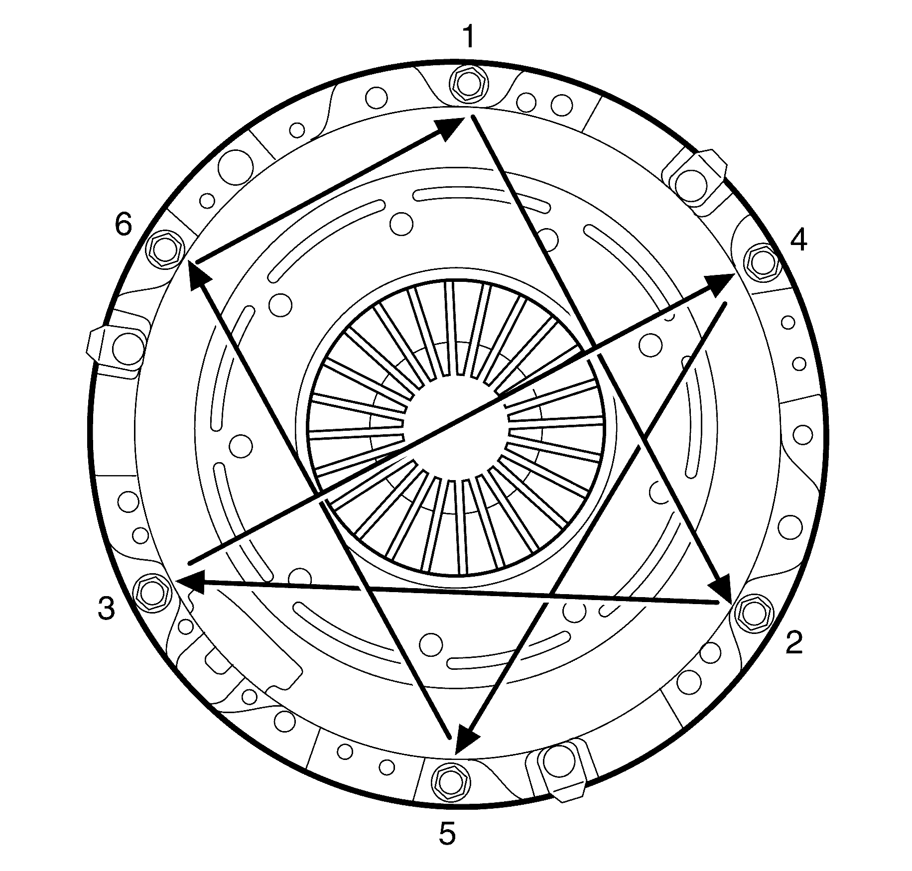
Tighten
Tighten the bolts a first pass to 15 N·m
(11 lb ft).
Tighten
Tighten the bolts a second pass to 30 N·m
(22 lb ft).
Notice: Refer to General Repair Instructions in the Preface section.
Clutch Assembly Replacement 6.0L Engine
Removal Procedure
- Disable the SIR system. Refer to SIR Disabling and Enabling in SIR.
- Disconnect the battery ground cable from the battery. Refer to Battery Negative Cable Disconnection and Connection.
- Raise and support the vehicle. Refer to Lifting and Jacking the Vehicle.
- Remove transmission. Refer to Transmission Replacement.
- Loosen all of the pressure plate to flywheel retaining bolts (4) working from opposite sides to avoid distortion.
- Continue loosening pressure plate to flywheel retaining bolts (4) from opposite sides until all are removed.
- Remove the pressure plate (3) and clutch driven plate (2) from the flywheel (1).
Caution: Refer to Battery Disconnect Caution in the Preface section.
Caution: Refer to Safety Glasses Caution in the Preface section.
Caution: Refer to Vehicle Lifting Caution in the Preface section.
Notice: Refer to General Repair Instructions in the Preface section.
Installation Procedure
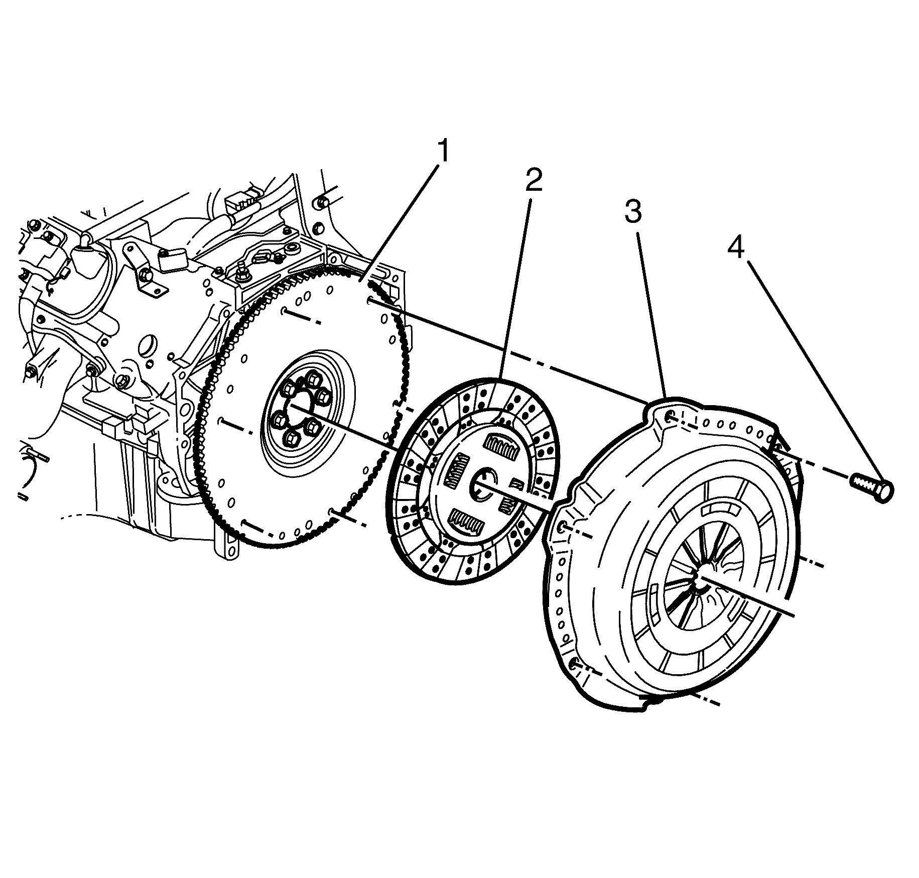
- While holding the pressure plate (3), and clutch driven plate (2), together, align them to the flywheel (1).
- Install the pressure plate to flywheel retaining bolts (4).
- Using a clutch driven plate centering tool (5) align the clutch driven plate (2) to the flywheel (1).
- Install the pressure plate bolts (4), and insert the clutch centering tool (5).
- Tighten the pressure plate to flywheel retaining bolts, using the sequence shown.
- Tighten the flywheel.
- Install transmission. Refer to Transmission Replacement.
- Bleed the clutch hydraulic system. Refer to Hydraulic Clutch Bleeding.
- Connect the battery ground cable to the battery. Refer to Battery Negative Cable Disconnection and Connection.
- Enable the SIR. Refer to SIR Disabling and Enabling in SIR.
- Press the clutch pedal several times to allow the self-adjusting pressure plate function to take affect.
- Road test vehicle for correct clutch operation.
Notice: Refer to General Repair Instructions in the Preface section.
Notice: Refer to Clutch Pressure Plate Adjustment in the Preface section.
Important: Apply any a small amount of grease to clutch driven plate splines or transmission input shaft splines.
Important: Install the clutch driven plate (2) with the short boss facing the flywheel (1). Flywheel side is stamped on the clutch driven plate hub (FW Side).
Important: The pressure plate to flywheel retaining bolts (4) must not to be tightened at this stage.
Do not tighten at this stage.
Notice: Refer to Fastener Notice in the Preface section.
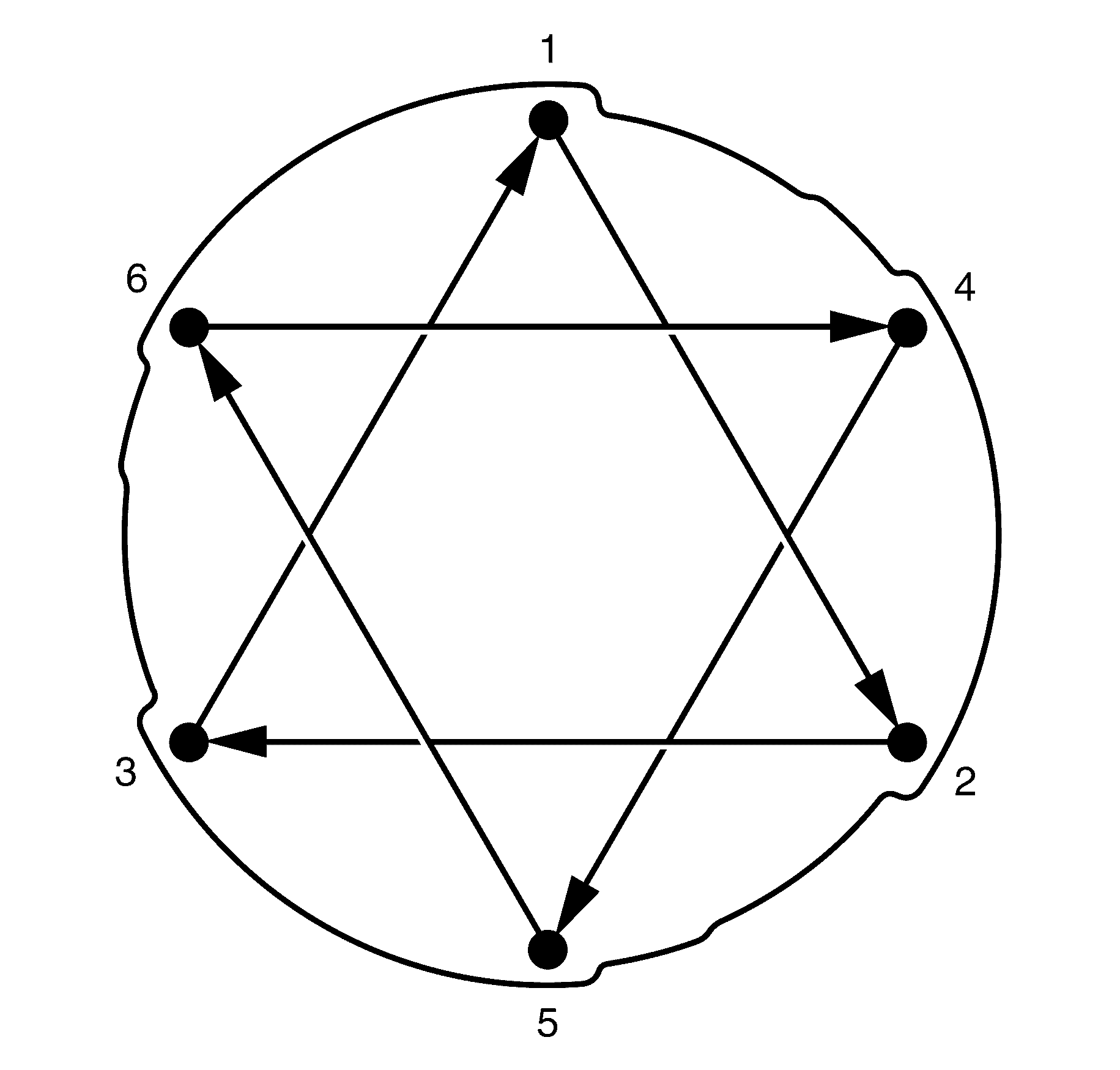
Tighten
Tighten the bolts a first pass to 15 N·m
(11 lb ft).
Tighten
Tighten the bolts a second pass to 35 N·m
(26 lb ft).
Tighten
Tighten the bolts a third pass to 55 N·m
(41 lb ft).
Tighten
Tighten the bolts a fourth pass to 70 N·m
(52 lb ft).
Notice: Refer to General Repair Instructions in the Preface section.
