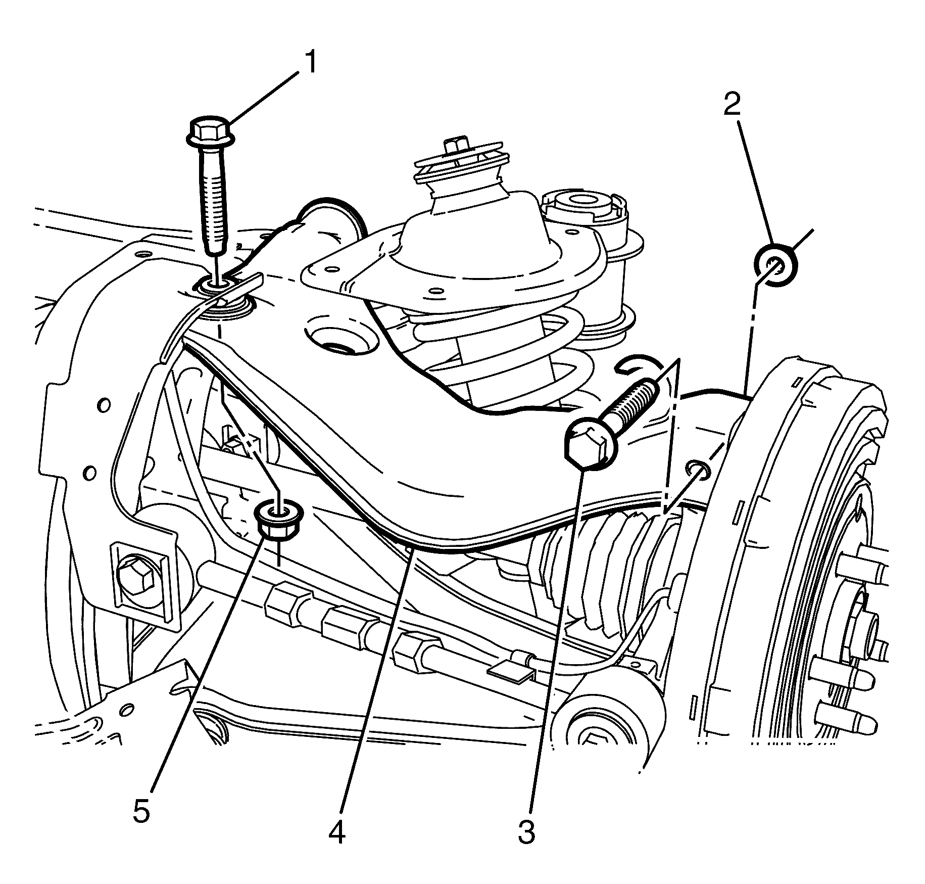
For 1990-2009 cars only
Removal Procedure
- Raise and support the vehicle. Refer to Lifting and Jacking the Vehicle.
- Remove the subframe. Refer to Rear Frame Replacement.
- Remove the upper control arm pivot bushing. Refer to Control Arm Bushing Replacement.
- Remove the upper control arm ball joint bushing to subframe retaining bolt (1) and nut (5).
- Remove the upper control arm to knuckle retaining bolt (3) and nut (2).
- Remove the upper control arm (4).
- Inspect all parts for wear and damage.
Caution: Refer to Safety Glasses Caution in the Preface section.
Caution: Refer to Vehicle Lifting Caution in the Preface section.

Important: Mark the location of the bolt and nut relative to the Y-Link for correct re-assembly.
Important: Prevailing torque nuts must be replaced after removal.
Discard the nut.
Discard the nut.
Installation Procedure
- Install the upper control arm (4) into the subframe.
- Install the upper control arm ball joint bushing to subframe retaining bolt (1) and NEW nut (5).
- Install the upper control arm to knuckle retaining bolt (3) and NEW nut (2).
- Install the upper control arm pivot bushing. Refer Control Arm Bushing Replacement.
- Install the subframe. Refer to Rear Frame Replacement.
- Remove the safety stands.
- Lower the vehicle to the ground.
- Check the vehicle rear wheel alignment and adjust if necessary. Refer to Wheel Alignment Specifications.
Notice: Refer to Fastener Notice in the Preface section.

Tighten
Tighten the bolt and nut a first pass to 80 N·m
(59 lb ft).
Tighten
Tighten the bolt and nut a final pass 120 Degrees.
Tighten
Tighten the bolt and nut a first pass to 60 N·m
(44 lb ft).
Tighten
Tighten the bolt and nut a final pass 90Degrees.
