Hydraulic Brake System Flushing CSV HSV VXR8 W427
- Clean the brake master cylinder brake master cylinder reservoir, brake line connections and reservoir cap.
- Inspect the brake fluid for the following conditions, indicating brake fluid contamination:
- Inspect the master cylinder reservoir cap diaphragm and the reservoir-to-master cylinder grommets for swelling, indicating brake fluid contamination.
- If the brake fluid WAS contaminated with an oil-based or a silicone-based substance, indicated by fluid separation and/or a swollen master cylinder reservoir cap diaphragm and/or swollen reservoir to master cylinder grommets, perform the following:
- If the brake fluid WAS NOT contaminated with an oil-based or a silicone-based substance, but was contaminated with water or dirt, rust, corrosion, and/or brake dust, replace the brake master cylinder reservoir cap diaphragm.
- Place a clean suitable container under the master cylinder.
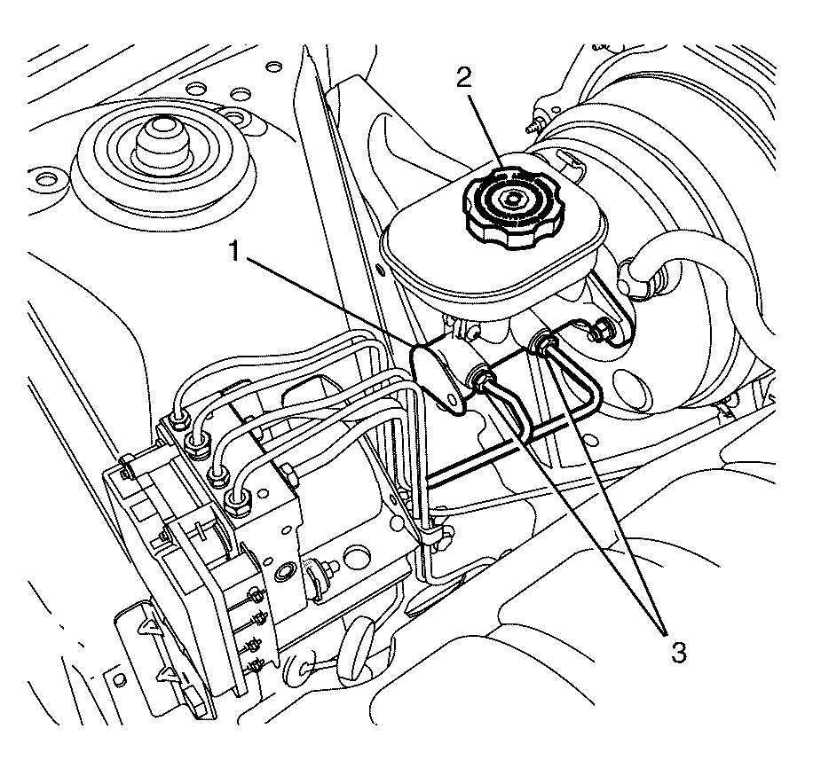
- Disconnect brake lines (3) from the master cylinder (1), then remove master cylinder reservoir cap (2).
- Allow the master cylinder (1) to drain into the container until empty.
- Install the brake lines (3) to master cylinder (1).
- Raise and support the vehicle. Refer to Lifting and Jacking the Vehicle.
- Remove all the wheels. Refer to Tire and Wheel Removal and Installation.
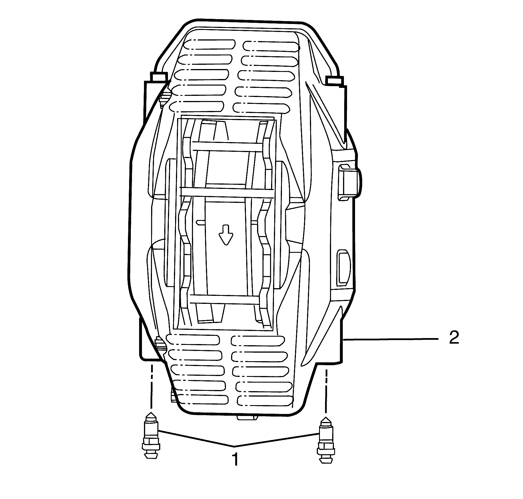
- Remove the left front brake caliper (2). Refer to Front Brake Caliper Replacement.
- Suspend the brake caliper (2) upside down with heavy mechanics wire or equivalent.
- Remove the bleed nipples (1) and drain contents of the brake caliper (2) into suitable receptacle.
- Install the bleed nipples (1) into the brake caliper (2).
- Reinstall the brake caliper (2). Refer to Front Brake Caliper Replacement.
- Repeat steps 12-17 for the remaining calipers. Refer to the following appropriate brake caliper procedure; Front Brake Caliper Replacement or Rear Brake Caliper Replacement.
- Bleed the braking system. Refer to Hydraulic Brake System Bleeding.
- Install the wheels. Refer to Tire and Wheel Removal and Installation.
- Lower the vehicle to the ground.
Caution: Refer to Safety Glasses Caution in the Preface section.
Caution: Refer to Vehicle Lifting Caution in the Preface section.
Caution: Refer to Brake Dust Caution in the Preface section.
Caution: Refer to Brake Fluid Caution in the Preface section.
Caution: Refer to Brake Fluid Irritant Caution in the Preface section.
Notice: Refer to Adding Fluid to the Brake System Notice in the Preface section.
Notice: Refer to Brake Fluid Effects on Paint and Electrical Components Notice in the Preface section.
| • | Fluid separation indicates 2 types of fluid are present. A substance other than the recommended brake fluid has been introduced into the brake hydraulic system. |
| - | Swirled appearance = oil-based substance. |
| - | Layered appearance = silicone-based substance. |
| • | Fluid discoloration, indicating the presence of moisture or particles that have been introduced into the brake hydraulic system. |
| - | Cloudy appearance = moisture. |
| - | Dark appearance/suspended particles in fluid = dirt, rust, corrosion and/or brake dust. |
| 4.1. | Remove ALL of the following components listed from the vehicle. Each component contains internal rubber seals/linings which have been contaminated by the contaminated brake fluid in the brake hydraulic system. |
Refer to the procedures indicated:
| 4.2. | Clean out all the hydraulic brake pipes using denatured alcohol, or equivalent. |
| 4.3. | Dry the brake pipes using non-lubricated, filtered air. |
| 4.4. | Replace ALL of the following components listed and install them to the vehicle. Each component contains internal rubber seals/linings which have been contaminated by the contaminated brake fluid in the brake hydraulic system. |
Refer to the procedures indicated:
| • | Replace the brake master cylinder reservoir cap diaphragm. |

Notice: Refer to Fastener Notice in the Preface section.
Tighten
Tighten the brake pipe fitting to 15 Nm (11 lb ft).
Notice: Support the brake caliper with heavy mechanic wire, or equivalent, whenever it is separated from its mount and the hydraulic flexible brake hose is still connected. Failure to support the caliper in this manner will cause the flexible brake hose to bear the weight of the caliper, which may cause damage to the brake hose and in turn may cause a brake fluid leak.
Important: Bolts with micro-encapsulated thread sealant must be replaced after removal.


Tighten
Tighten the circuit bleed nipples to 17 Nm
(12 lb ft).
