Tools Required
| • | 7208 Drive Shaft Remover. |
| • | KM-468 Hub Holding Tool. |
Removal Procedure - Up to 13 Aug 2007
- Raise and support the vehicle. Refer to Lifting and Jacking the Vehicle.
- Remove the rear wheel. Refer to Tire and Wheel Removal and Installation.
- Remove the rear brake disc. Refer to Rear Brake Rotor Replacement.
- Install the KM-468 (1) to the wheel hub (2) with two inverted wheel nuts (3).
- Remove the wheel drive shaft retaining nut (2) and washer (1).
- Remove the 7208 from the wheel hub.
- Disconnect the wheel speed sensor electrical connector (1).
- Detach the wheel speed sensor wiring harness mounting clip (2) from the knuckle (3).
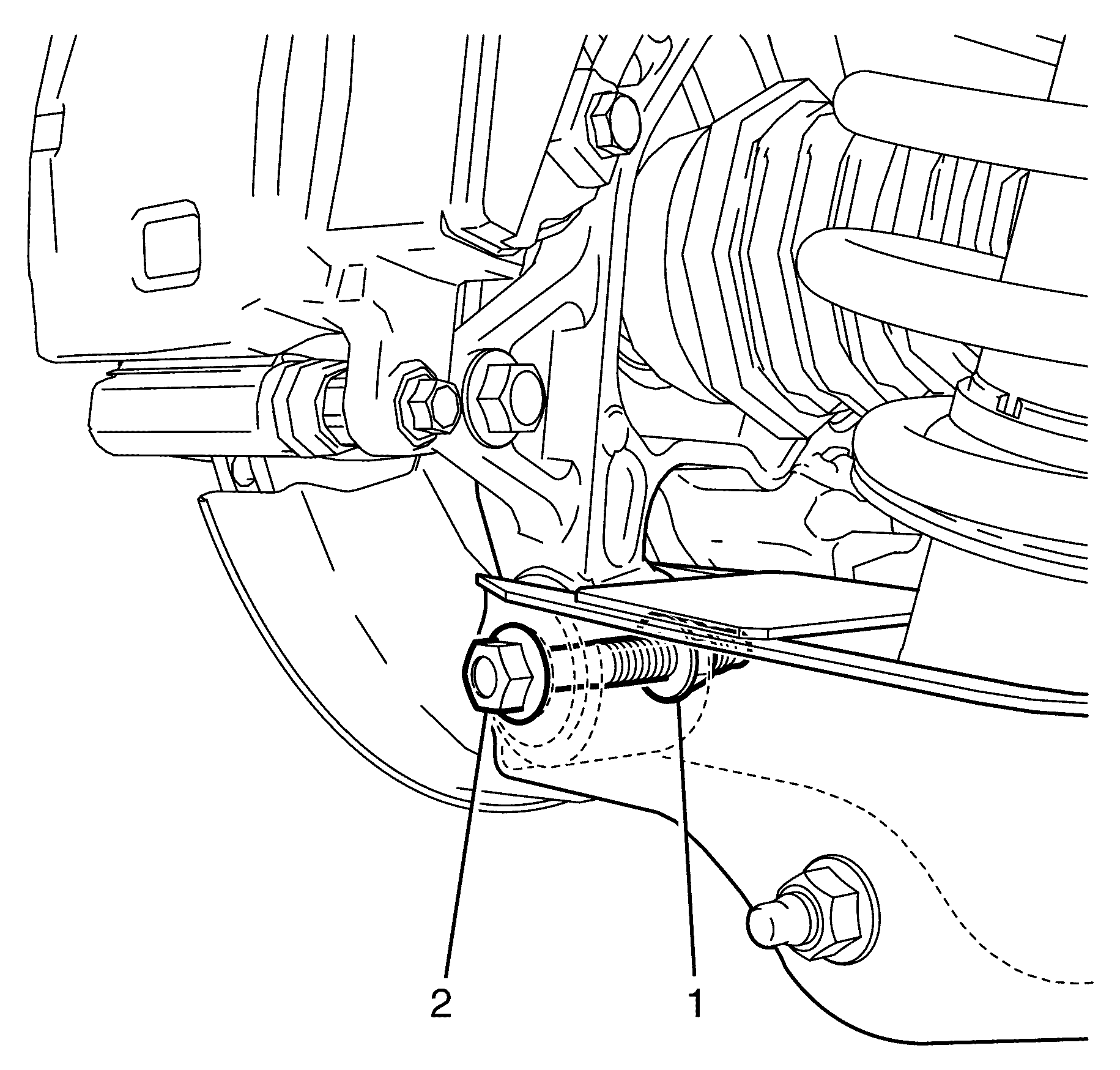
- Remove the lower control arm to knuckle retaining bolt (2) and nut (1).
- Remove the I-Link to knuckle retaining bolt (1).
- Remove the Y-Link to knuckle retaining bolt (2) and nut (1).
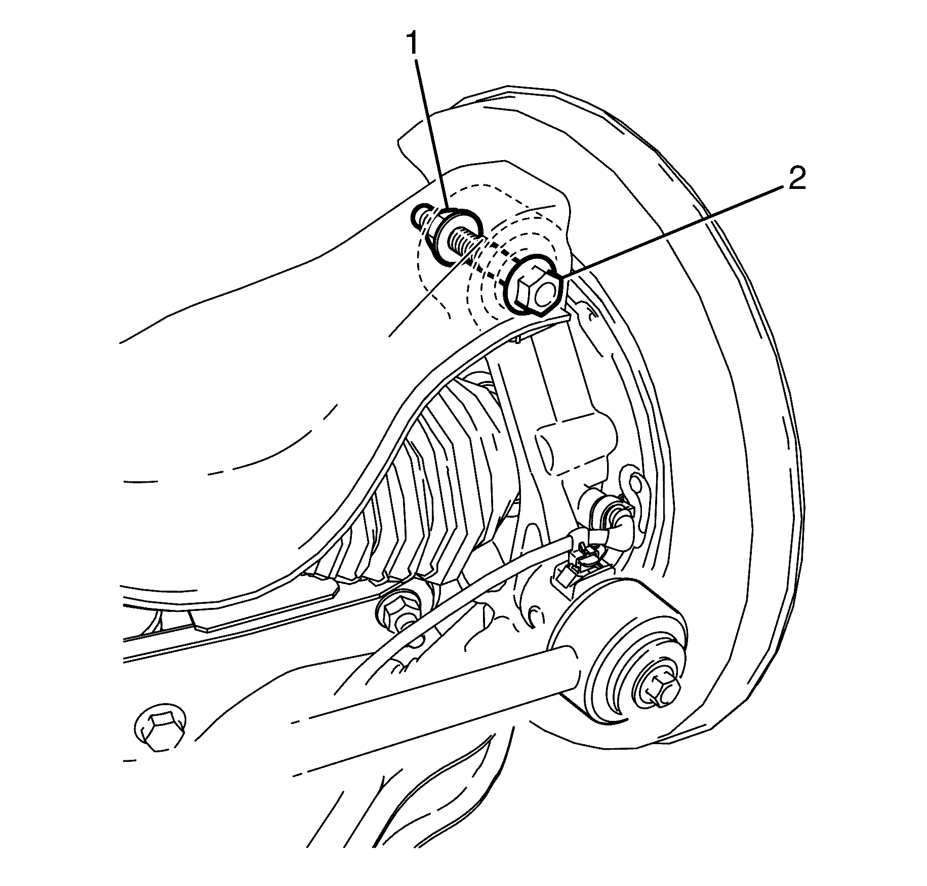
- Loosen the upper control arm to knuckle retaining bolt (2) and nut (1).
- Secure the rear driveshaft with wire to protect it from damage.
- Install the 7208 to the wheel hub.
- Press the wheel drive shaft from the wheel hub using the 7208 (1).
- Remove the 7208 from the wheel hub.
- Remove the upper control arm to knuckle bolt (2) and nut (1).
- Remove the wheel hub and knuckle assembly.
- Disassemble the wheel hub and knuckle assembly. Refer to Rear Wheel Bearing and Hub Replacement.
Caution: Refer to Safety Glasses Caution in the Preface section.
Caution: Refer to Vehicle Lifting Caution in the Preface section.
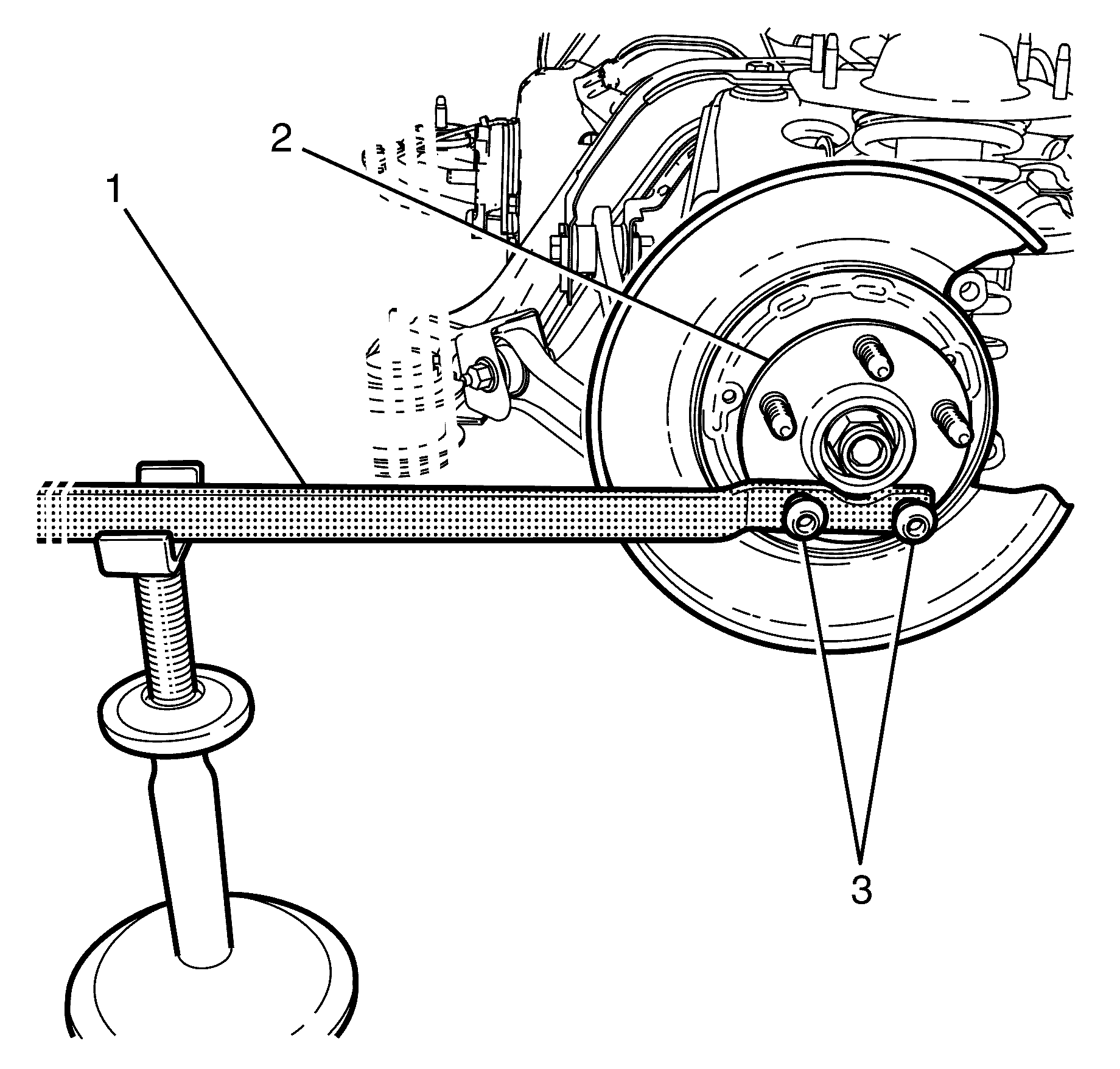
Support the KM-468 outer end on a safety stand.
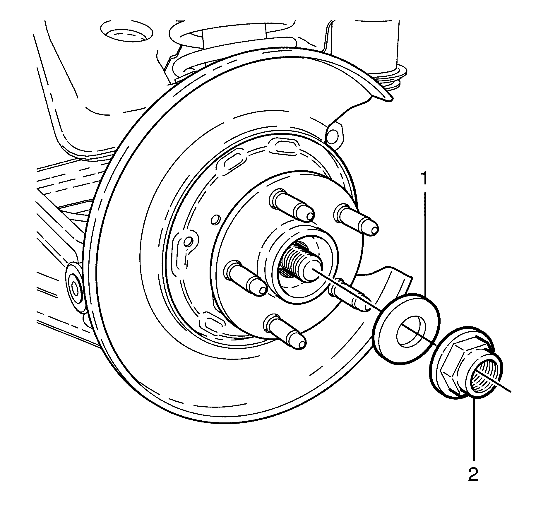
Important: The wheel drive shaft retaining nut (2) and washer (1) must be discarded after removal.
| • | Discard the nut. |
| • | Discard the washer. |
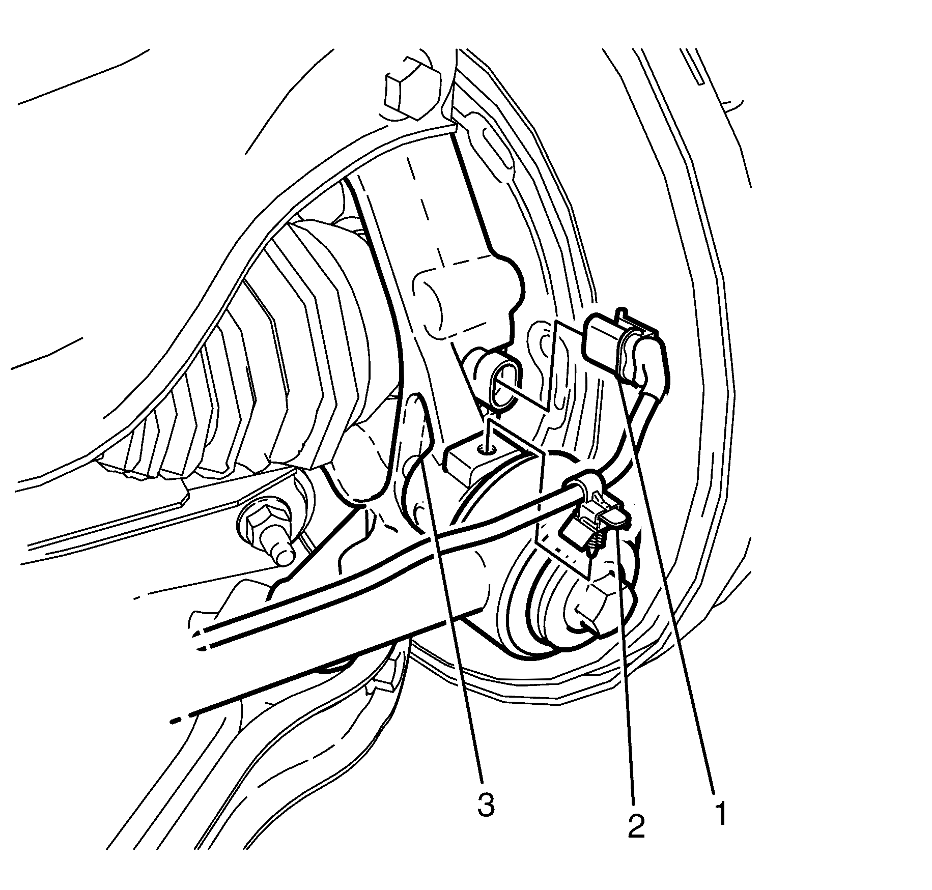
Important: The wheel speed sensor cable must be secured to protect it from damage.
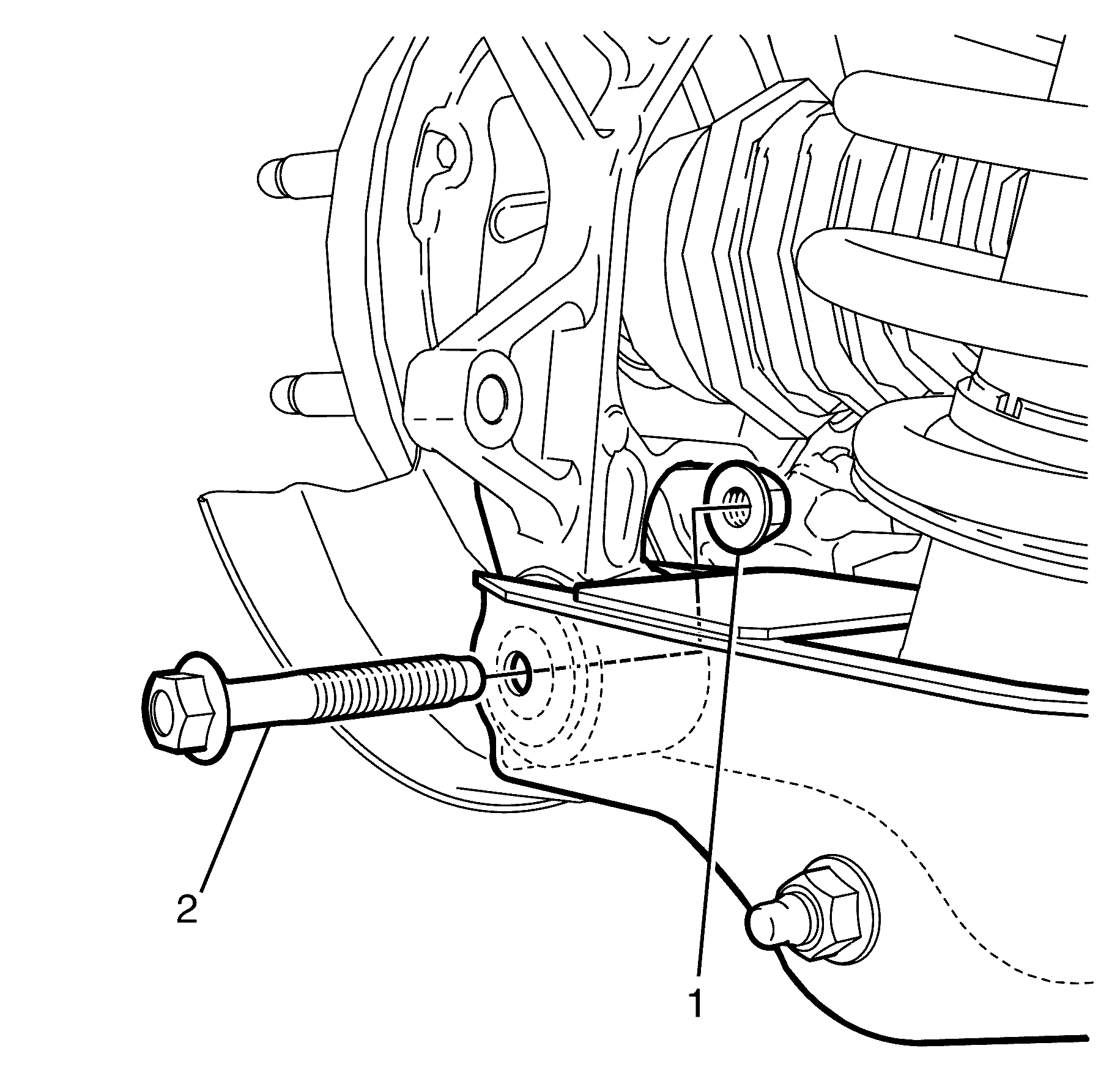
Important: Prevailing torque nuts must be discarded after removal.
Discard the nut.
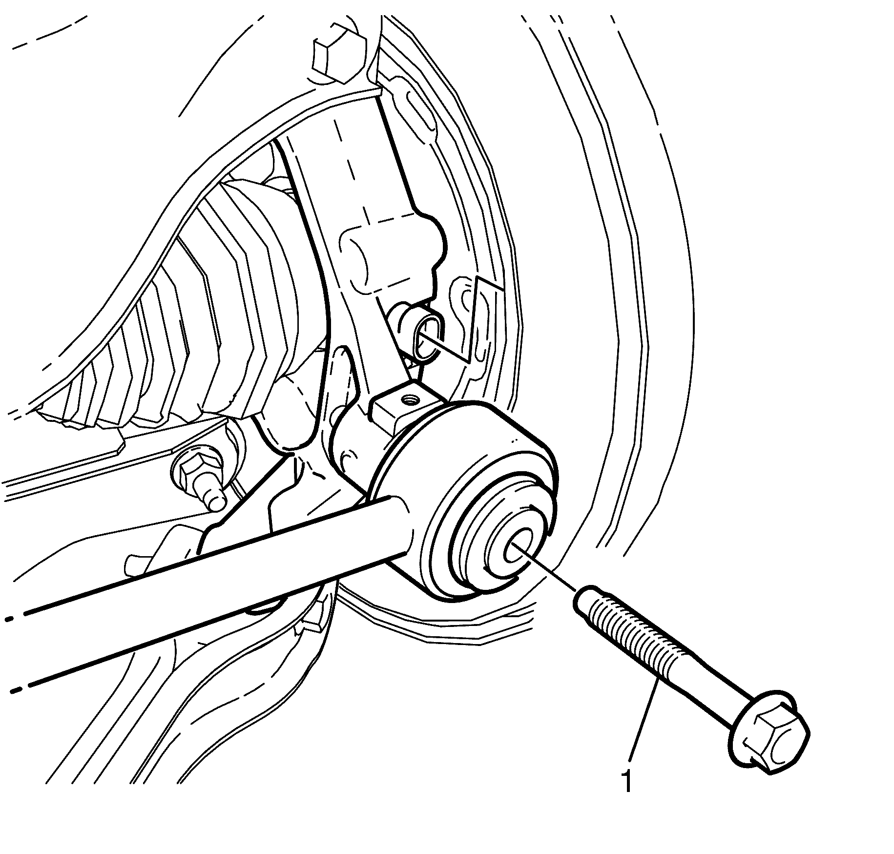
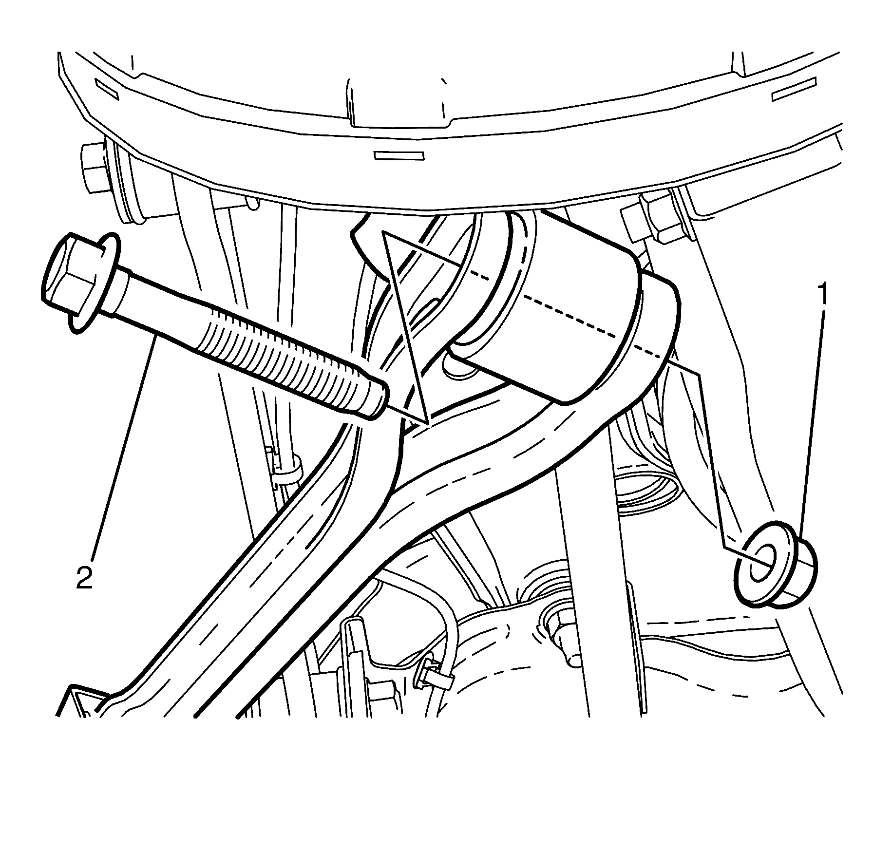
Important: Mark the location of the bolt and nut relative to the Y-Link for correct re-assembly.
Important: Prevailing torque nuts must be discarded after removal.
Discard the nut.
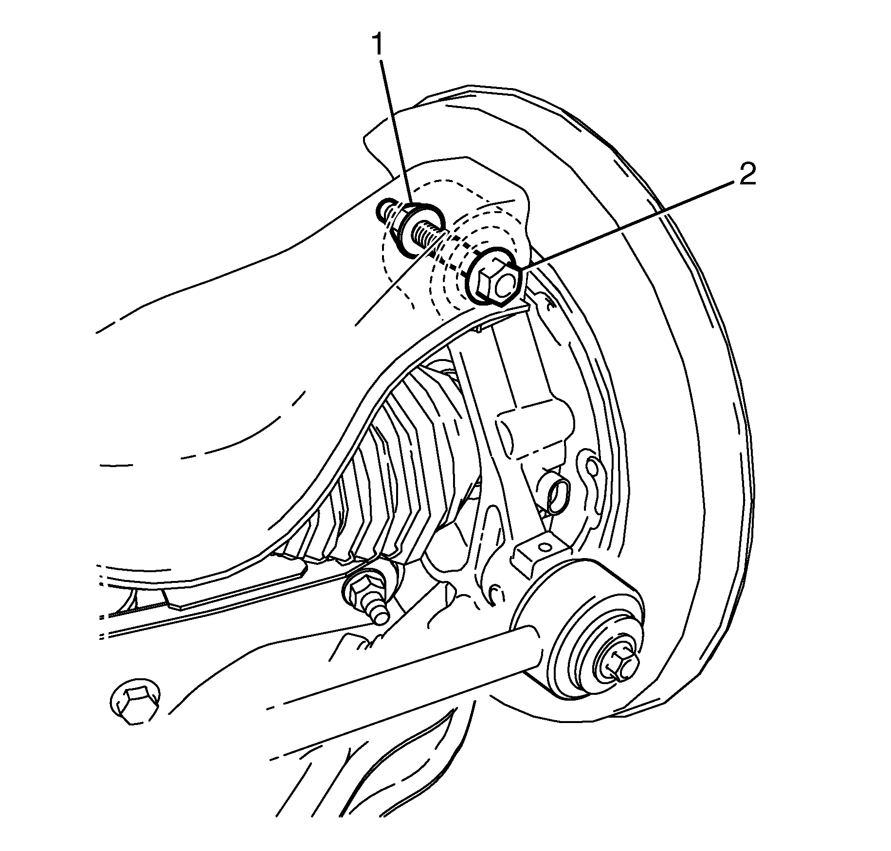
Important: Mark the location of the bolt and nut relative to the upper control arm for correct re-assembly.
Do not remove the bolt and nut.
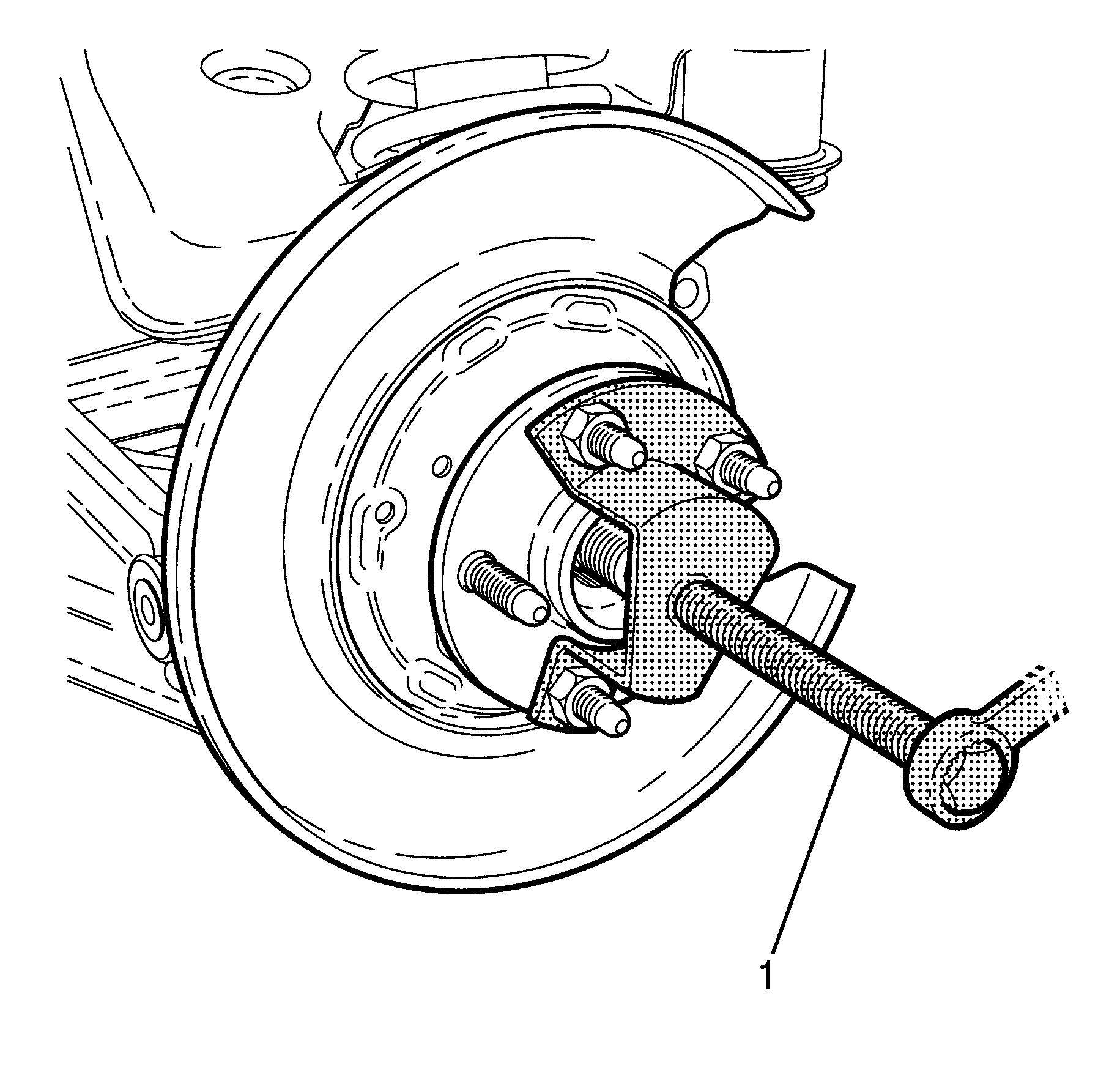
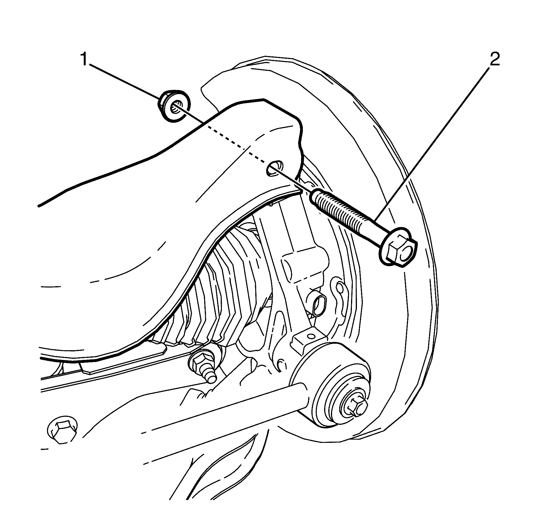
Important: Prevailing torque nuts must be discarded after removal.
Installation Procedure - Up to 13 Aug 2007
- Assemble the wheel hub and knuckle assembly. Refer to Rear Wheel Bearing and Hub Replacement.
- Install the wheel hub and knuckle assembly to the upper control arm.
- Install the upper control arm to knuckle retaining bolt (2) and nut (1).
- Push the wheel drive shaft outer splined end (4) into the splined cavity (5) of the wheel hub (1).
- Remove the wheel drive shaft securing wire, used in the removal process to prevent damage.
- Install the lower control arm (3) to the knuckle (4).
- Install the lower control arm to knuckle retaining bolt (2) and NEW nut (1).
- Install the Y-Link (4) to the knuckle (2).
- Install the Y-Link to knuckle retaining bolt (1) and NEW nut (3).
- Install the I-Link (4) to the knuckle (1).
- Install the I-Link to knuckle retaining bolt (2) and washer (3).
- Connect the wheel speed sensor electrical connector (1).
- Attach the wheel speed sensor wiring harness mounting clip (2) to the knuckle (3).
- Install NEW retaining washer (1) and NEW nut (2) to the wheel drive shaft.
- Install the KM-468
- Preferred Method
- Remove the KM-468 (1).
- Install the rear brake disc. Refer to Rear Brake Rotor Replacement
- Install the rear wheel. Refer to Tire and Wheel Removal and Installation
- Remove the safety stands.
- Lower the vehicle to the ground.
- Bounce the vehicle several times to settle the suspension.
- Tighten the upper control arm to knuckle retaining bolt (2) and NEW nut (1).
- Tighten the lower control arm to knuckle retaining bolt (2) and NEW nut (1).
- Tighten the Y-Link to knuckle retaining bolt (2) and NEW nut (1).
- Tighten the I-Link to knuckle retaining bolt (1).
- Check the vehicle rear wheel alignment and adjust if necessary. Refer to Wheel Alignment Specifications.

Important: The upper control arm to knuckle retaining bolt (2) and nut (1) must not to be fully tightened at this stage.
Do not fully tighten at this stage.
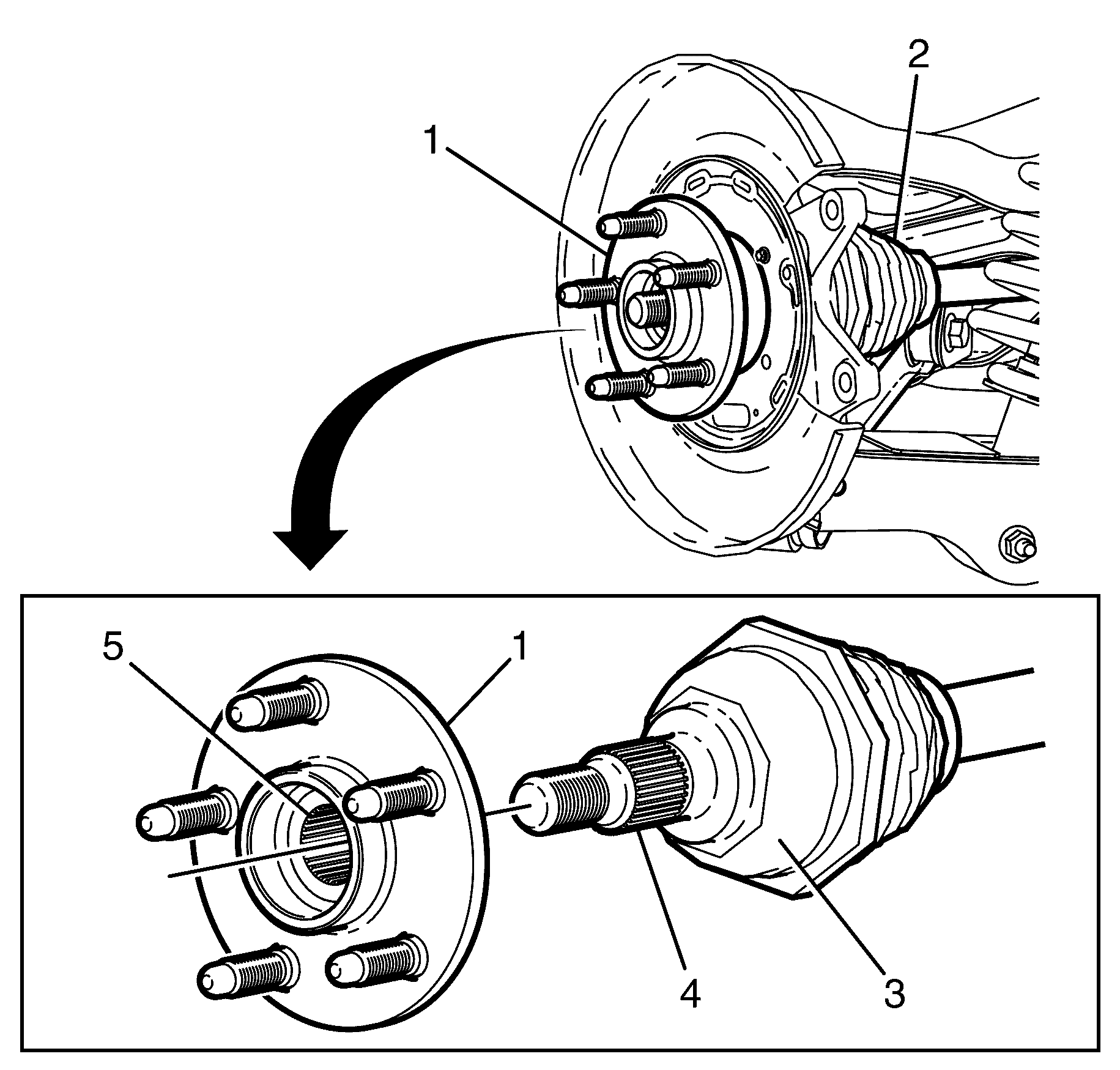
Important: Lightly lubricate the wheel drive shaft outer splined end (4) with the recommended differential lubricant.
Important: Do not excessively push the wheel drive shaft (3) through the wheel hub (1).
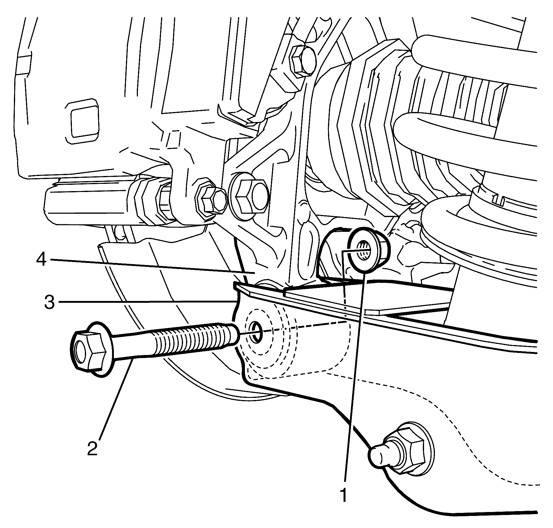
Important: The lower control arm to knuckle retaining bolt (2) and nut (1) must not to be fully tightened at this stage.
Do not fully tighten at this stage.
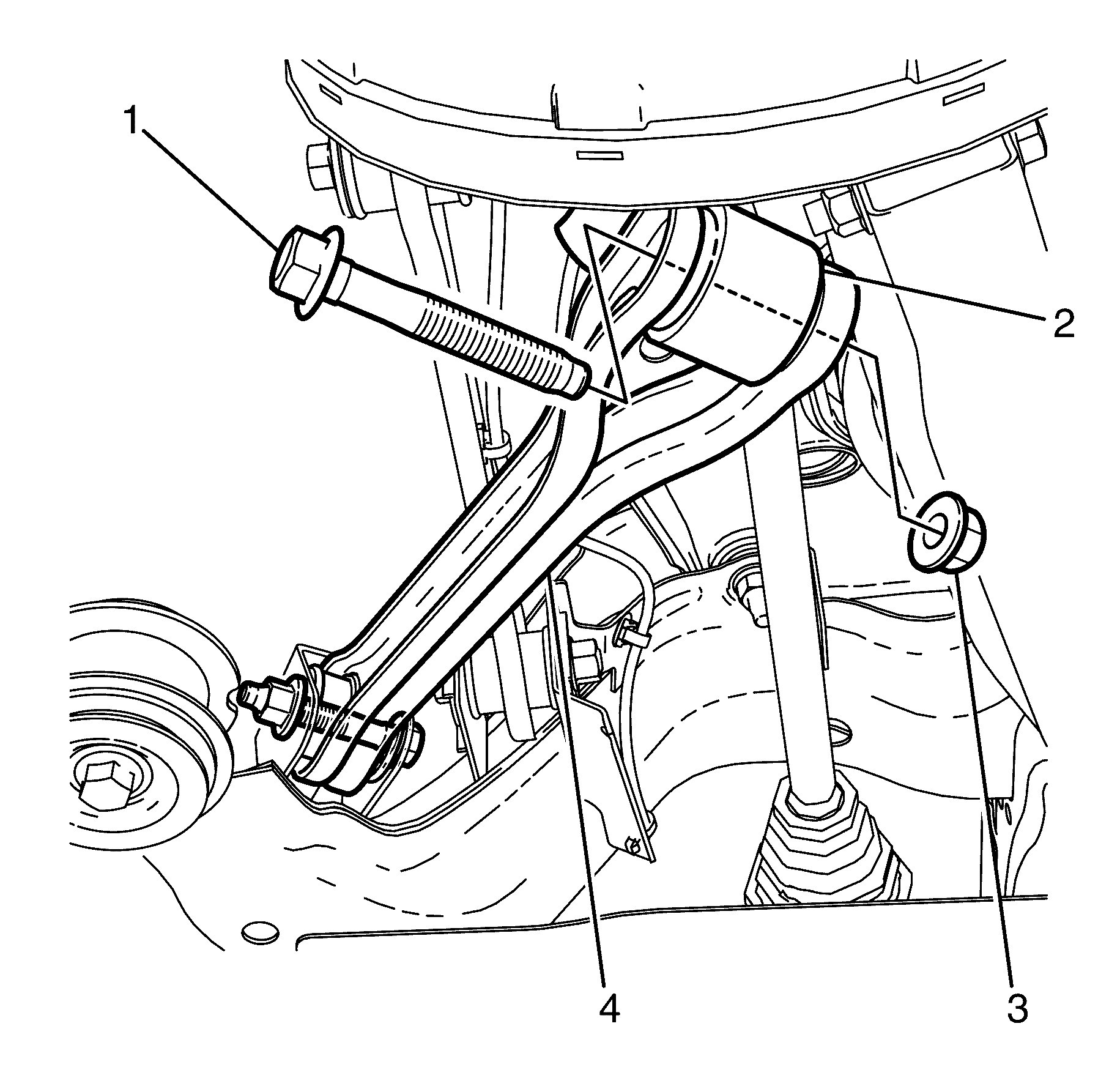
Important: The Y-Link to knuckle retaining bolt (1) and nut (3) must not to be fully tightened at this stage.
Do not fully tighten at this stage.
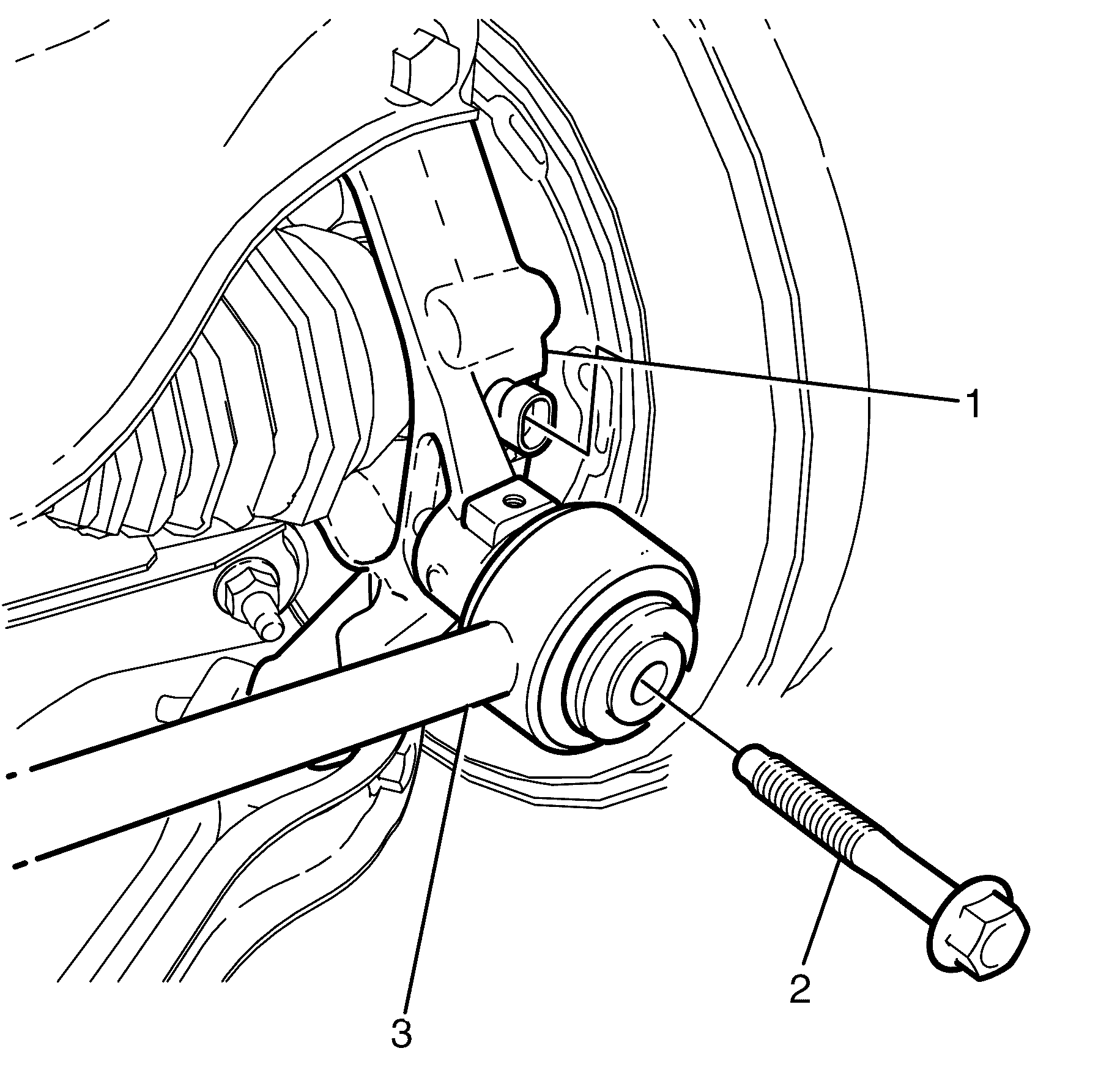
Important: The I-Link to knuckle retaining bolt (2) and nut (3) must not to be fully tightened at this stage.
Do not fully tighten at this stage.

Notice: Refer to Fastener Notice in the Preface section.

Important: A NEW nut and NEW washer must be used when installing the wheel drive shaft.
Notice: Refer to Fastener Notice in the Preface section.
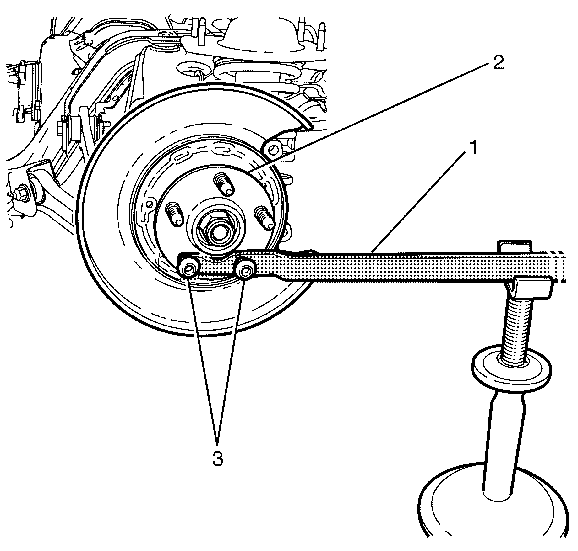
Support the KM-468
Notice: Refer to Fastener Notice in the Preface section.
Important: There are two suitable methods of tightening the wheel drive shaft retaining nut. DO NOT EXCEED THE SPECIFIED TIGHTENING VALUES, otherwise premature bearing failure may result.
Tighten
Tighten the nut on first pass to 150 N·m
(111 lb ft).
Loosen
Loosen the nut on second pass by 180 Degrees.
Tighten
Tighten the nut on third pass to 425 N·m
(313 lb ft)
Crimp nut.
Alternate Method
Tighten
Tighten the nut on first pass to 150 N·m
(111 lb ft).
Loosen
Loosen the nut on second pass by 180 Degrees.
Tighten
Tighten the nut on the third pass to 50 N·m
(37 lb ft)
Tighten
Tighten the nut on the forth pass by 45 Degrees
Crimp nut.
Important: The weight of the vehicle must be on a level surface and on all four wheels before fully tightening the nuts and bolts.
Important: Align the bolt to the mark made prior to removal.
Tighten
Tighten the bolt and nut first pass to 60 N·m(44 lb ft).
Tighten the bolt and nut final pass to 90 Degrees.
Tighten
Tighten the nut a first pass to 40 N·m
(30 lb ft).
Tighten the nut in a final pass 120 Degrees.
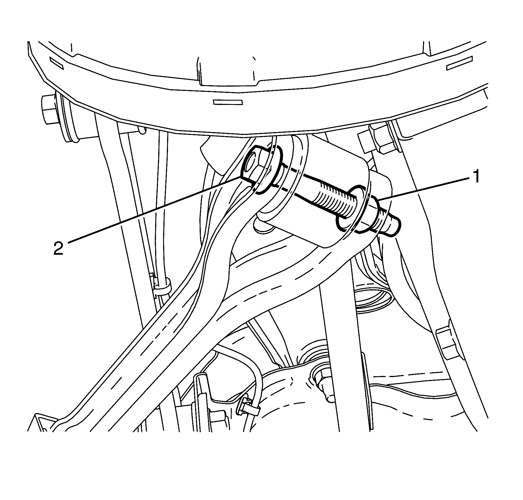
Important: Align the mark from bolt to Y-Link made prior to removal.
Tighten
Tighten the bolt and nut a first pass to 40 N·m
(30 lb ft).
Tighten the bolt and nut in a second pass 120 Degrees.
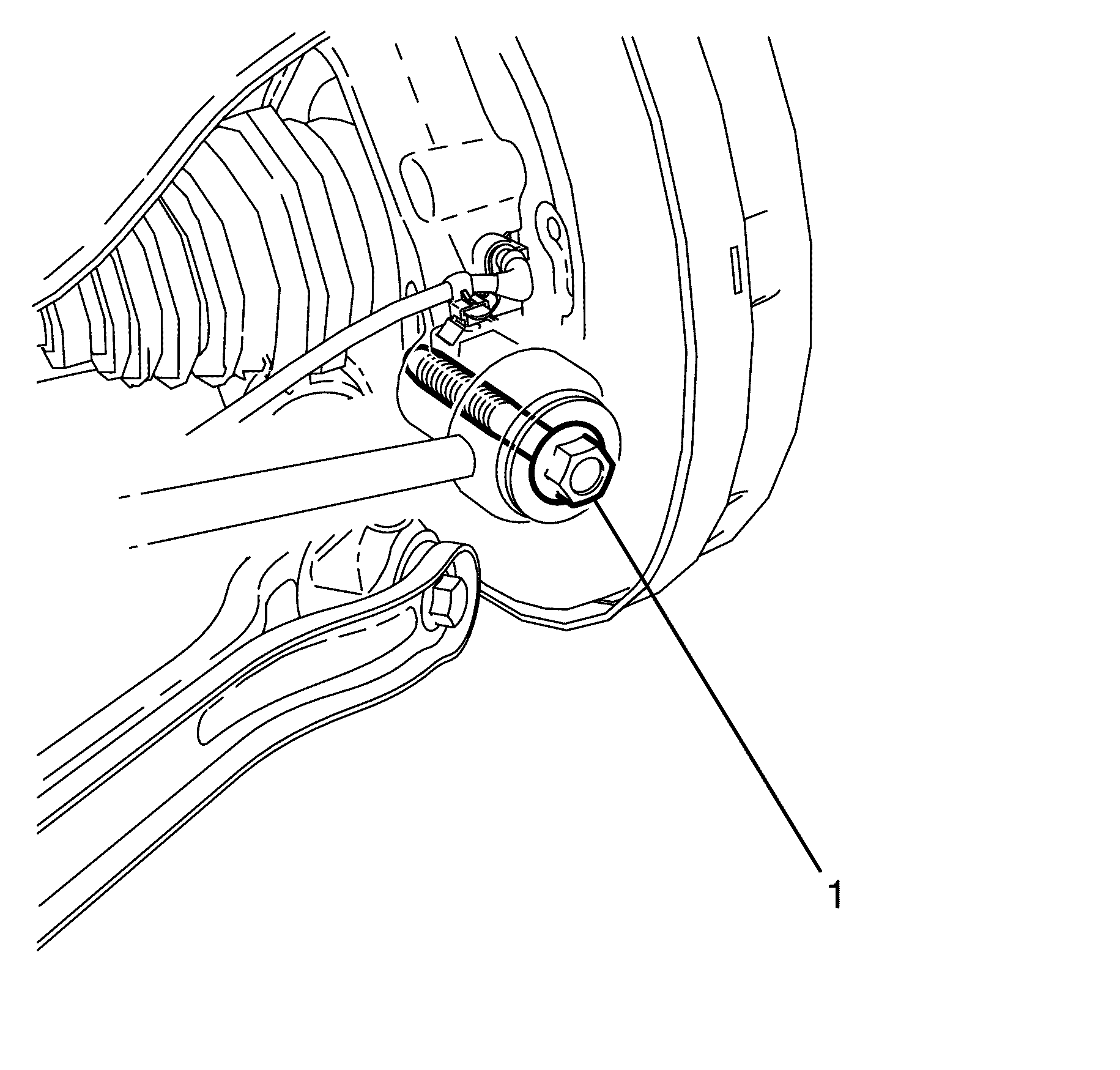
Tighten
Tighten the bolt to 140 N·m (103 lb ft).
Removal Procedure - After 13 Aug 2007
- Raise and support the vehicle. Refer to Lifting and Jacking the Vehicle.
- Remove the rear wheel. Refer to Tire and Wheel Removal and Installation.
- Remove the rear brake disc. Refer to Rear Brake Rotor Replacement.
- Install the KM-468 (1) to the wheel hub (2) with two inverted wheel nuts (3).
- Remove the wheel drive shaft retaining nut (2) and washer (1).
- Disconnect the wheel speed sensor electrical connector (1).
- Detach the wheel speed sensor wiring harness mounting clips (2, 3 and 4).
- Remove the lower control arm to knuckle retaining bolt (2) and nut (1).
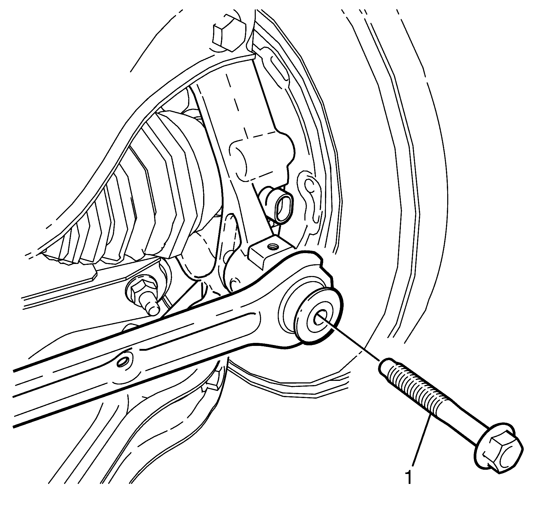
- Remove the I-Link to knuckle retaining bolt (1).
- Remove the Y-Link to knuckle retaining bolt (2) and nut (1).
- Loosen the upper control arm to knuckle retaining bolt (2) and nut (1).
- Install the 7208 (1) to the wheel hub (2).
- Press the wheel drive shaft from the wheel hub using the 7208 (1).
- Remove the 7208 (1) from the wheel hub (2).
- Remove the upper control arm to knuckle bolt (2) and nut (1).
- Remove the wheel hub and knuckle assembly.
- Disassemble the wheel hub and knuckle assembly. Refer to Rear Wheel Bearing and Hub Replacement.
Caution: Refer to Safety Glasses Caution in the Preface section.
Caution: Refer to Vehicle Lifting Caution in the Preface section.

Support the KM-468 (1) outer end on a safety stand.

Important: The wheel drive shaft retaining nut (2) and washer (1) must be discarded after removal.
| • | Discard the nut. |
| • | Discard the washer. |
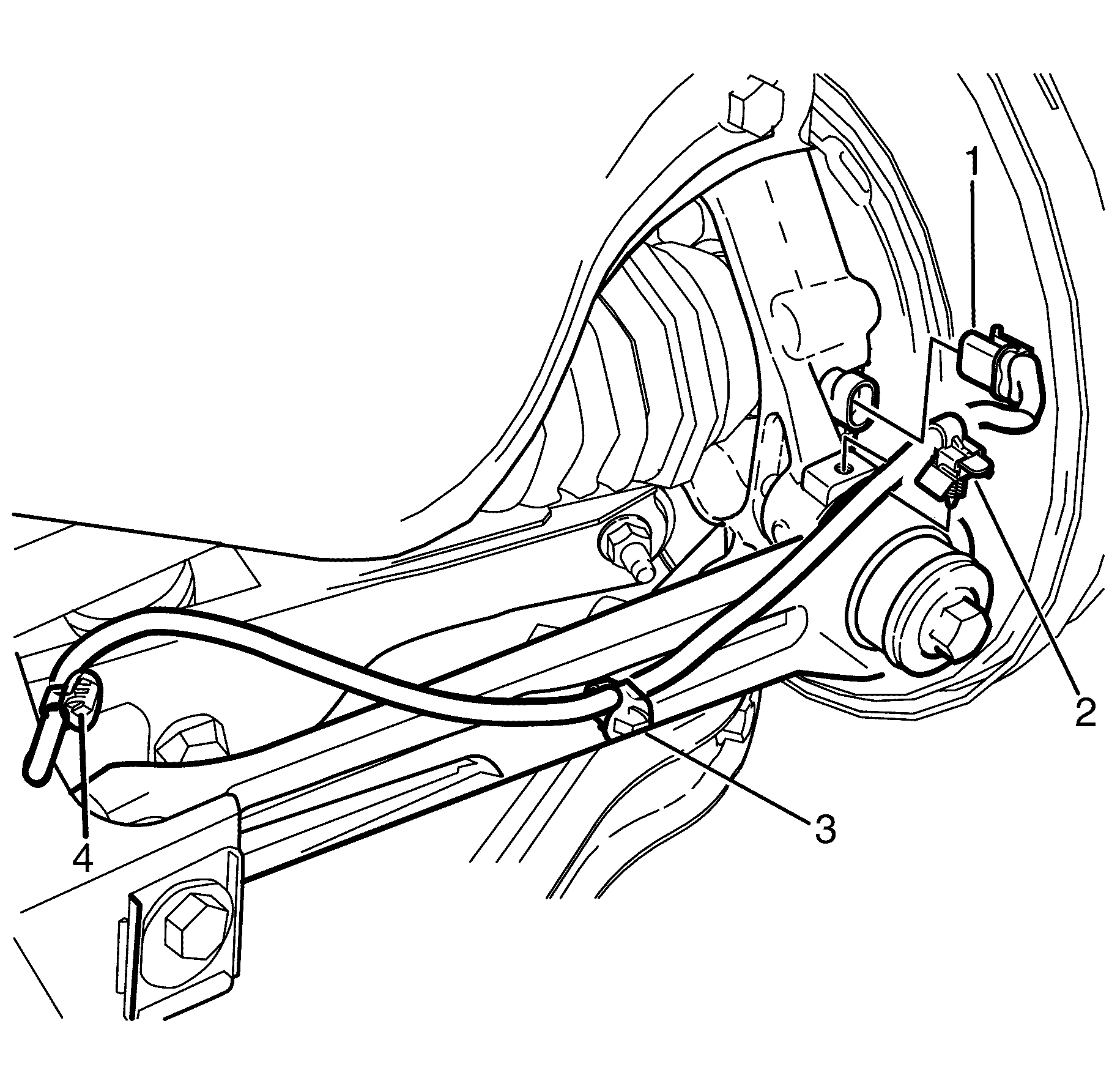
Important: The wheel speed sensor cable must be secured to protect it from damage.

Important: Prevailing torque nuts must be discarded after removal.
Discard the nut.

Important: Mark the location of the Y-Link to knuckle retaining bolt and nut relative to the Y-Link for correct re-assembly.
Important: Prevailing torque nuts must be discarded after removal.
Discard the nut.
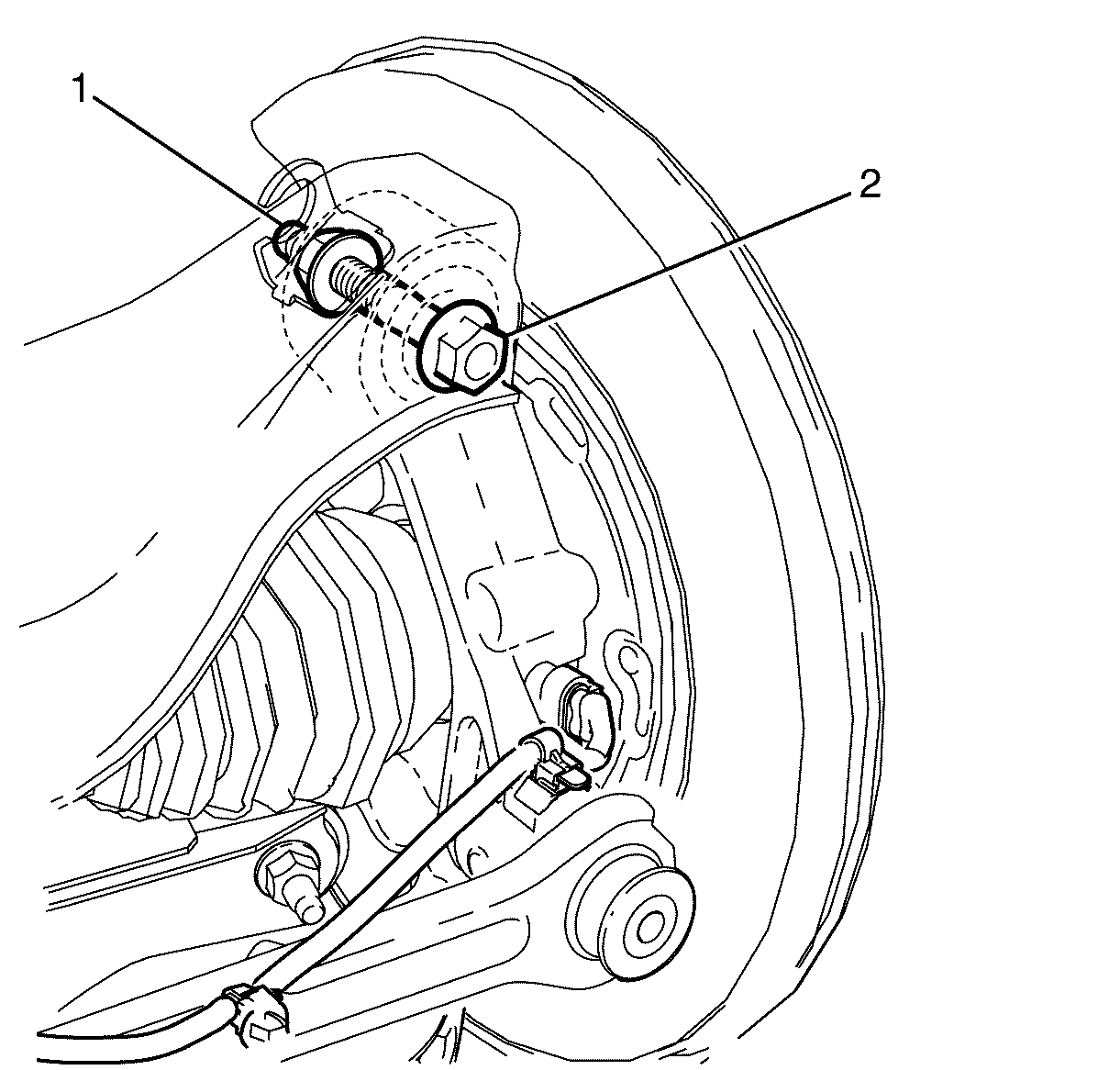
Important: Mark the location of the bolt and nut relative to the upper control arm for correct assembly.
Do not remove the bolt and nut.
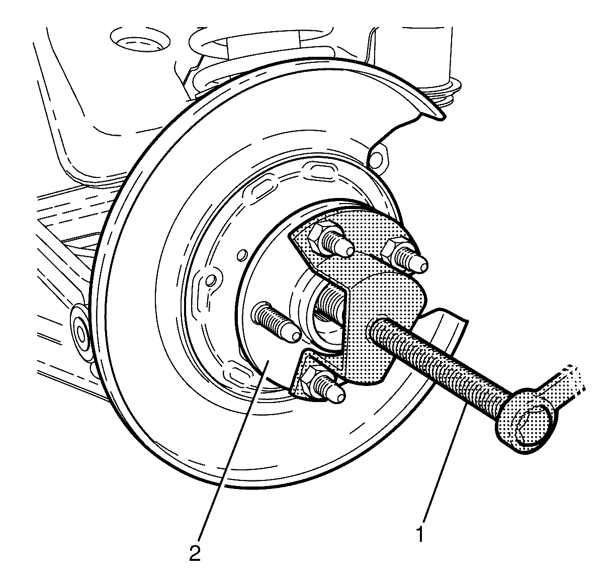
Important: Secure the wheel drive shaft with wire to protect it from damage.
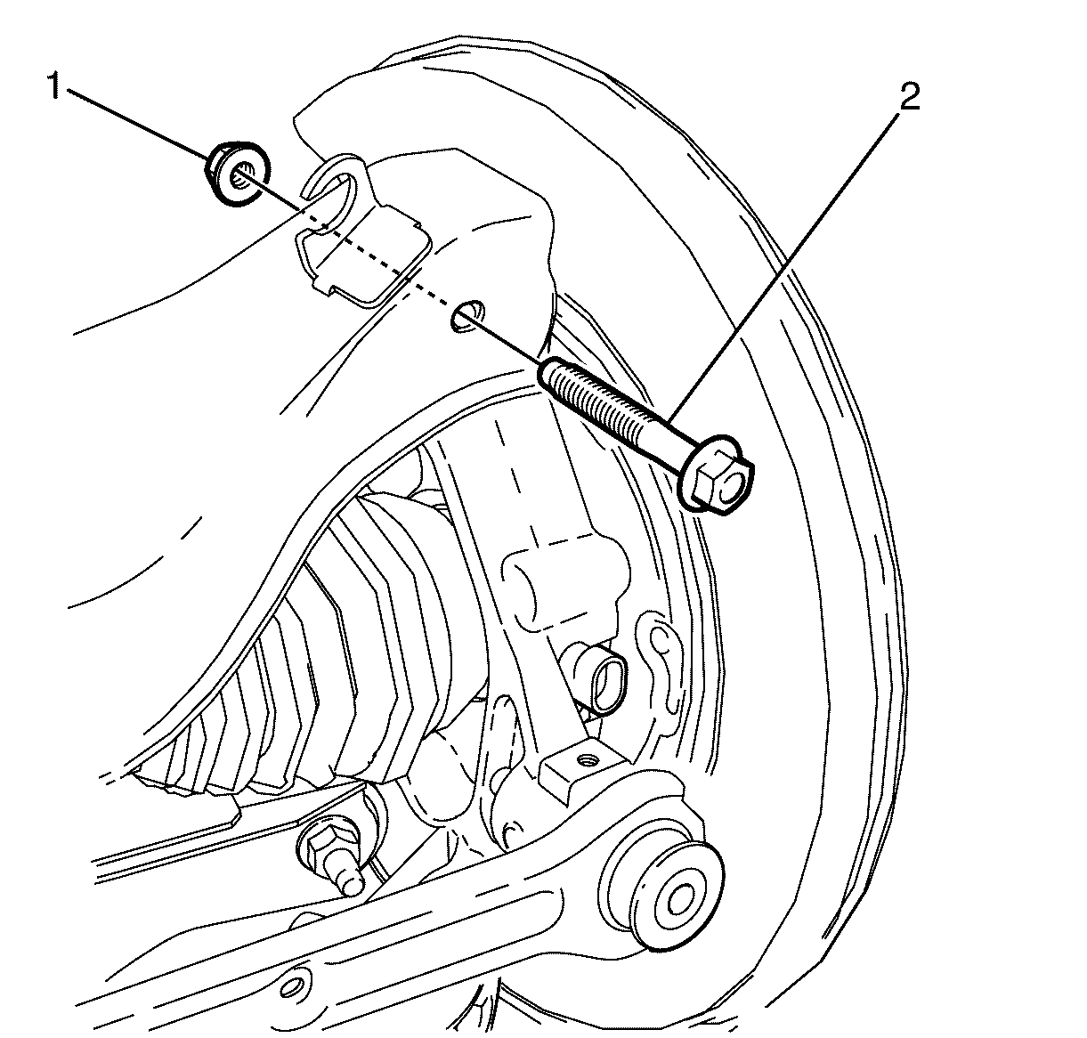
Important: Prevailing torque nuts must be discarded after removal.
Discard the nut.
Installation Procedure - After 13 Aug 2007
- Assemble the wheel hub and knuckle assembly. Refer to Rear Wheel Bearing and Hub Replacement.
- Install the wheel hub and knuckle assembly to the upper control arm.
- Install the upper control arm to knuckle retaining bolt (2) and NEW nut (1).
- Push the wheel drive shaft outer splined end (3) into the splined cavity (4) of the wheel hub (1).
- Remove the wheel drive shaft securing wire, used in the removal process to prevent damage.
- Install the lower control arm to knuckle retaining bolt (2) and NEW nut (1).
- Install the Y-Link (4) to the knuckle (2).
- Install the Y-Link to knuckle retaining bolt (1) and NEW nut (3).
- Install the I-Link to knuckle retaining bolt (1).
- Connect the wheel speed sensor electrical connector (1).
- Attach the wheel speed sensor wiring harness mounting clips (2, 3 and 4).
- Install the NEW wheel drive shaft retaining nut (2) and NEW washer (1).
- Install the KM-468 (1) to the wheel hub (2) with two inverted wheel nuts (3).
- Preferred Method
- Remove the KM-468 (1).
- Install the rear brake disc. Refer to Rear Brake Rotor Replacement.
- Install the rear wheel. Refer to Tire and Wheel Removal and Installation.
- Remove the safety stands.
- Lower the vehicle to the ground.
- Bounce the vehicle several times to settle the suspension.
- Tighten the upper control arm to knuckle retaining bolt (2) and NEW nut (1).
- Tighten the lower control arm to knuckle retaining bolt (2) and NEW nut (1).
- Tighten the Y-Link to knuckle retaining bolt (2) and NEW nut (1).
- Tighten the I-Link to knuckle retaining bolt (1).
- Check the vehicle rear wheel alignment and adjust if necessary. Refer to Wheel Alignment Specifications.

Important: The upper control arm to knuckle retaining bolt (2) and NEW nut (1) must not to be fully tightened at this stage.
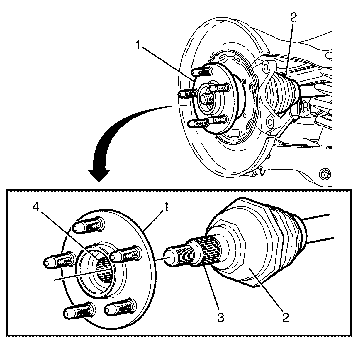
Important: Lightly lubricate the wheel drive shaft outer splined end (3) with the recommended differential lubricant.
Important: Do not excessively push the wheel drive shaft (2) through the wheel hub (1).

Important: The lower control arm to knuckle retaining bolt (2) and NEW nut (1) must not to be fully tightened at this stage.

Important: The Y-Link to knuckle retaining bolt (1) and NEW nut (3) must not to be fully tightened at this stage.

Important: The I-Link to knuckle retaining bolt (1) must not to be fully tightened at this stage.


Important: A NEW wheel drive shaft retaining nut and NEW washer must be used when installing the wheel drive shaft.
Notice: Refer to Fastener Notice in the Preface section.

Support the KM-468 (1) outer end on a safety stand.
Notice: Refer to Fastener Notice in the Preface section.
Important: There are two suitable methods of tightening the wheel drive shaft retaining nut. DO NOT EXCEED THE SPECIFIED TIGHTENING VALUES, otherwise premature bearing failure may result.
Tighten
Tighten the nut on first pass to 150 N·m
(111 lb ft).
Loosen
Loosen the nut on second pass by 180 Degrees.
Tighten
Tighten the nut on third pass to 425 N·m
(313 lb ft)
Crimp nut.
Alternate Method
Tighten
Tighten the nut on first pass to 150 N·m
(111 lb ft).
Loosen
Loosen the nut on second pass by 180 Degrees.
Tighten
Tighten the nut on the third pass to 50 N·m
(37 lb ft)
Tighten
Tighten the nut on the forth pass by 45 Degrees
Crimp nut.
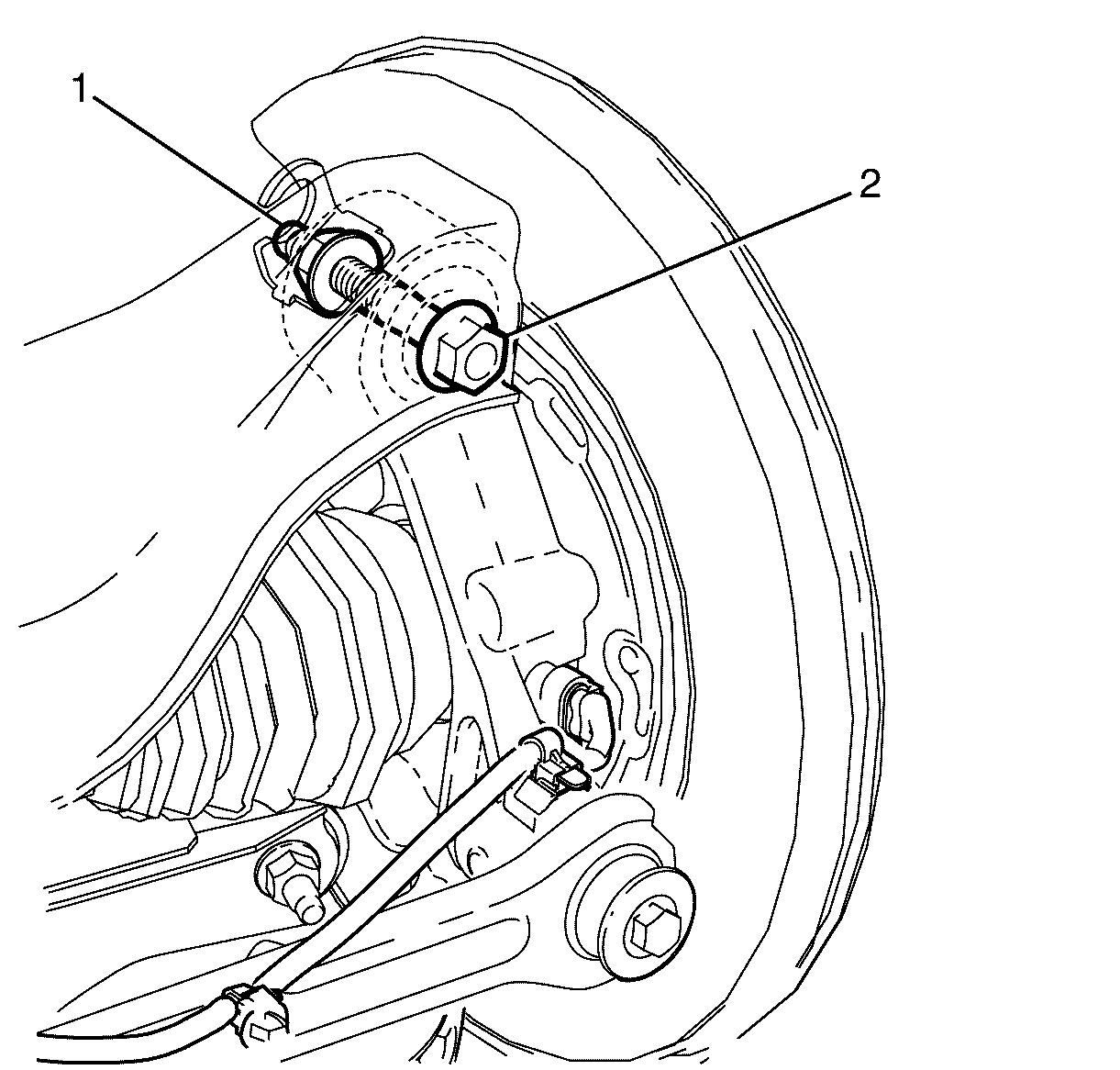
Important: The weight of the vehicle must be on a level surface and on all four wheels before fully tightening the nuts and bolts.
Important: Align the bolt to the mark made prior to removal.
Tighten
Tighten the bolt and nut first pass to 60 N·m(44 lb ft).
Tighten the bolt and nut final pass to 90 Degrees.

Tighten
Tighten the nut a first pass to 40 N·m
(30 lb ft).
Tighten the nut in a final pass 120 Degrees.

Important: Align the mark from bolt to Y-Link made prior to removal.
Tighten
Tighten the bolt and nut a first pass to 40 N·m
(30 lb ft).
Tighten the bolt and nut in a second pass 120 Degrees.
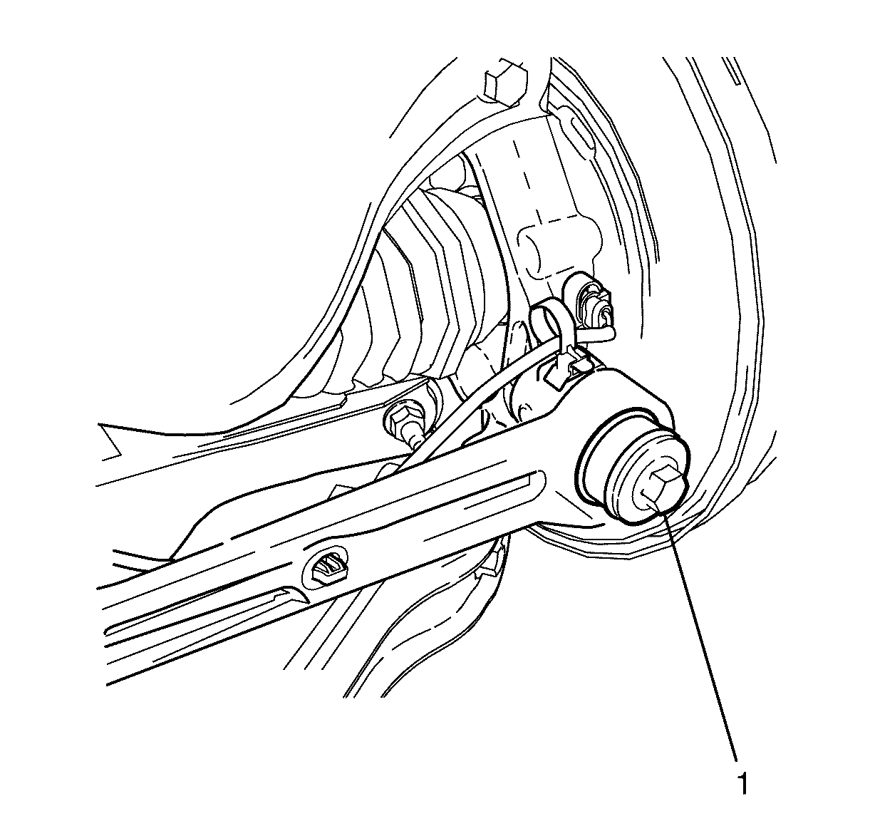
Tighten
Tighten the bolt to 140 N·m (103 lb ft).
