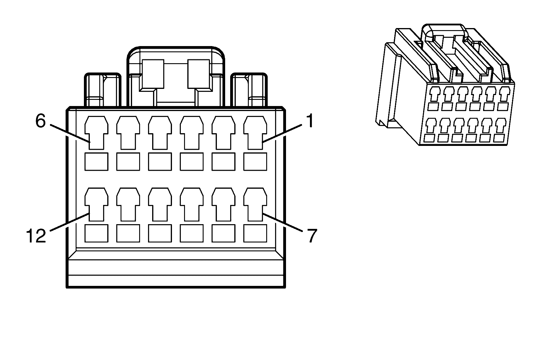
| Table 1: | Telematics Module - X1 |
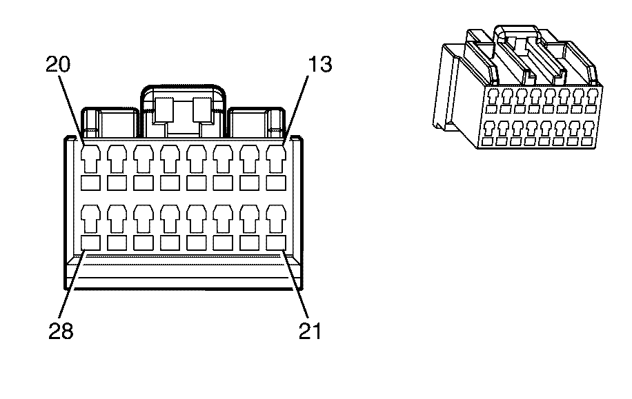
| Table 2: | Telematics Module - X2 |
| Table 3: | Telematics Module - X3 |
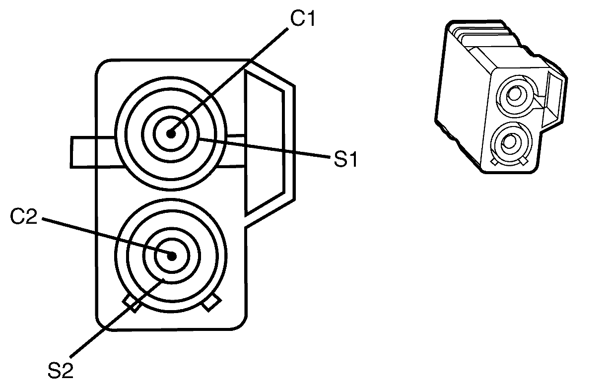
| Table 4: | Telematics Antenna |

| |||
|---|---|---|---|
Connector Part Information | 040 Multilock Mark II Series | ||
Pin | Wire Colour | Wire Size | Function |
X1-1 | XX | XX | Ground |
X1-2 | -- | -- | -- |
X1-3 | L-GN | 0.3 | Low Speed GMLAN Serial Data |
X1-4 | -- | -- | -- |
X1-5 | -- | -- | -- |
X1-6 | -- | -- | -- |
X1-7 | OG/WH | 0.5 | Battery Positive Voltage |
X1-8 | YE/BK | 0.3 | Keypad Green LED Signal |
X1-9 | BN/WH | 0.3 | Keypad Red LED Signal |
X1-10 | -- | -- | -- |
X1-11 | -- | -- | -- |
X1-12 | -- | -- | -- |

| |||
|---|---|---|---|
Connector Part Information | 040 Multilock Series | ||
Pin | Wire Colour | Wire Size | Function |
X2-13 | D-GN/WH | 0.3 | Keypad Signal |
X2-14 | -- | -- | -- |
X2-15 | L-BU | 0.3 | Telephone Audio Signal (+) |
X2-16 | OG/BK | 0.3 | Telephone Audio Signal (-) |
X2-17 | L-BU | 0.3 | Telephone Audio Signal (+) |
X2-18 | PK | 0.3 | Cellular Telephone Microphone Low Reference |
X2-19 | GN | 0.3 | Cellular Microphone Signal |
X2-20 | TN | 0.5 | Left Front Speaker Output (+) |
OG | 0.5 | Front Center Speaker Output (+) | |
X2-21 | L-GN/BK | 0.3 | Keypad Supply Voltage |
X2-22 | PK | 0.5 | Ignition 1 Voltage |
X2-23 | WH | 0.3 | Telephone Audio Signal Mute |
X2-24 | -- | -- | -- |
X2-25 | OG/BK | 0.3 | Telephone Audio Signal (-) |
X2-26 | -- | -- | -- |
X2-27 | -- | -- | -- |
X2-28 | GY | 0.5 | Left Front Speaker Output (-) |
L-BU | 0.5 | Front Center Speaker Output (-) | |

| |||
|---|---|---|---|
Connector Part Information | |||
Pin | Wire Colour | Wire Size | Function |
P1 | GY | -- | GSM antenna post |
S1 | BARE | -- | GSM antenna shield |
P2 | GY | -- | GPS antenna post |
S2 | BARE | -- | GPS antenna shield |

| |||
|---|---|---|---|
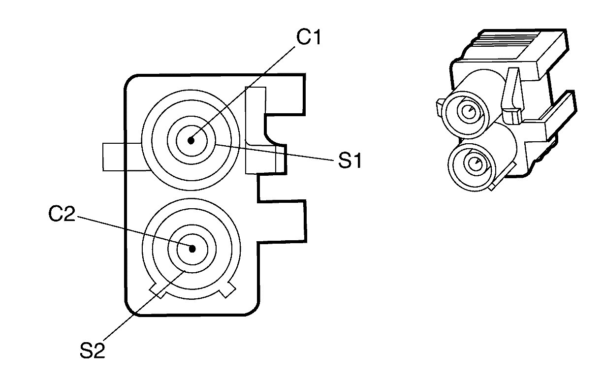
Connector Part Information | |||
Pin | Wire Colour | Wire Size | Function |
P1 | GY | -- | GSM antenna post |
S1 | BARE | -- | GSM antenna shield |
P2 | GY | -- | GPS antenna post |
S2 | BARE | -- | GPS antenna shield |
