For 1990-2009 cars only
Removal Procedure
- Remove the engine cover. Refer to Engine Cover Replacement.
- Depressurize the fuel system. Refer to Fuel Pressure Relief.
- Disconnect the battery ground cable. Refer to Battery Negative Cable Disconnection and Connection.
- Drain the cooling system. Refer to Cooling System Draining and Filling.
- Remove the air intake duct. Refer to Air Cleaner Inlet Duct Replacement.
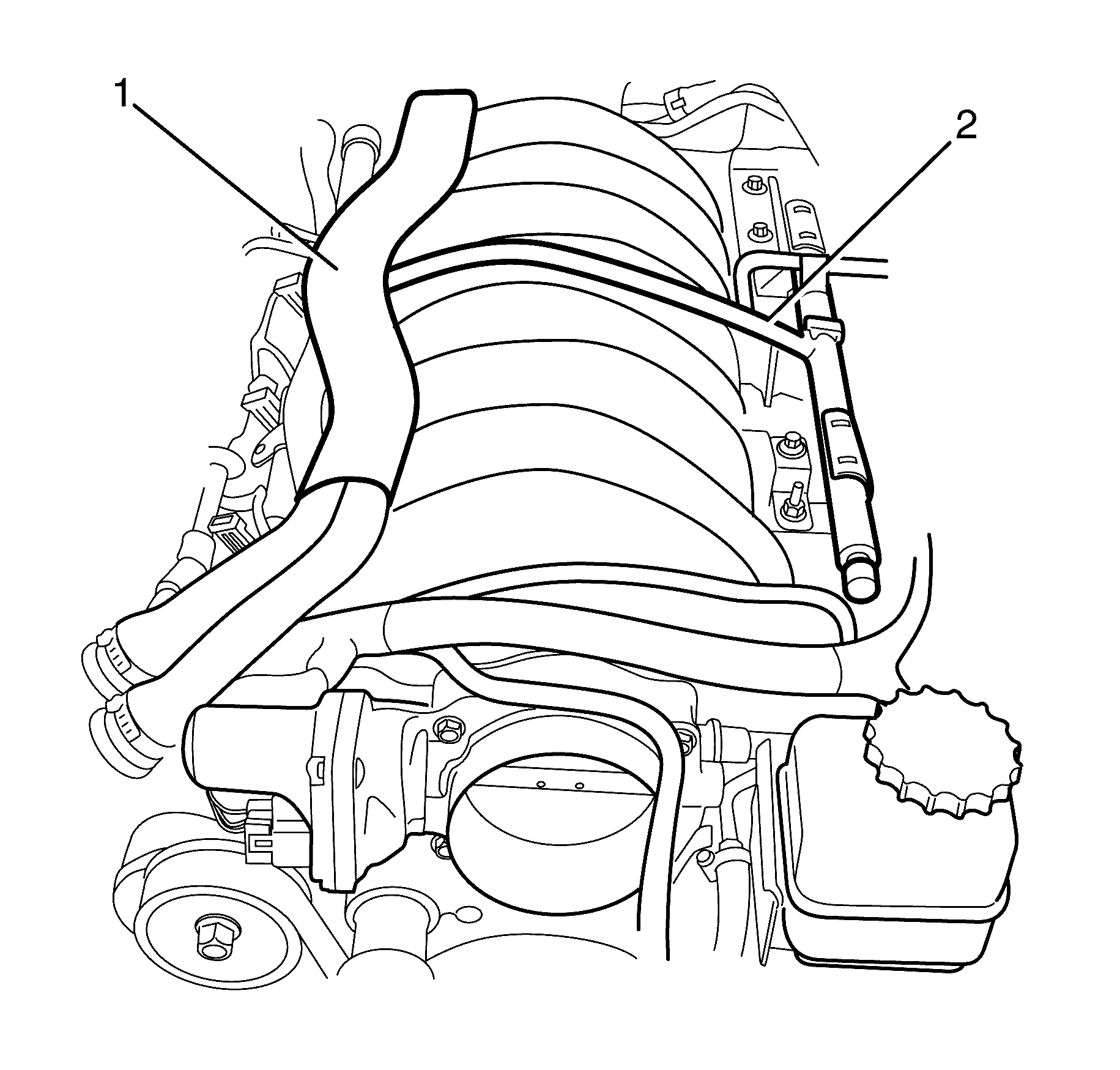
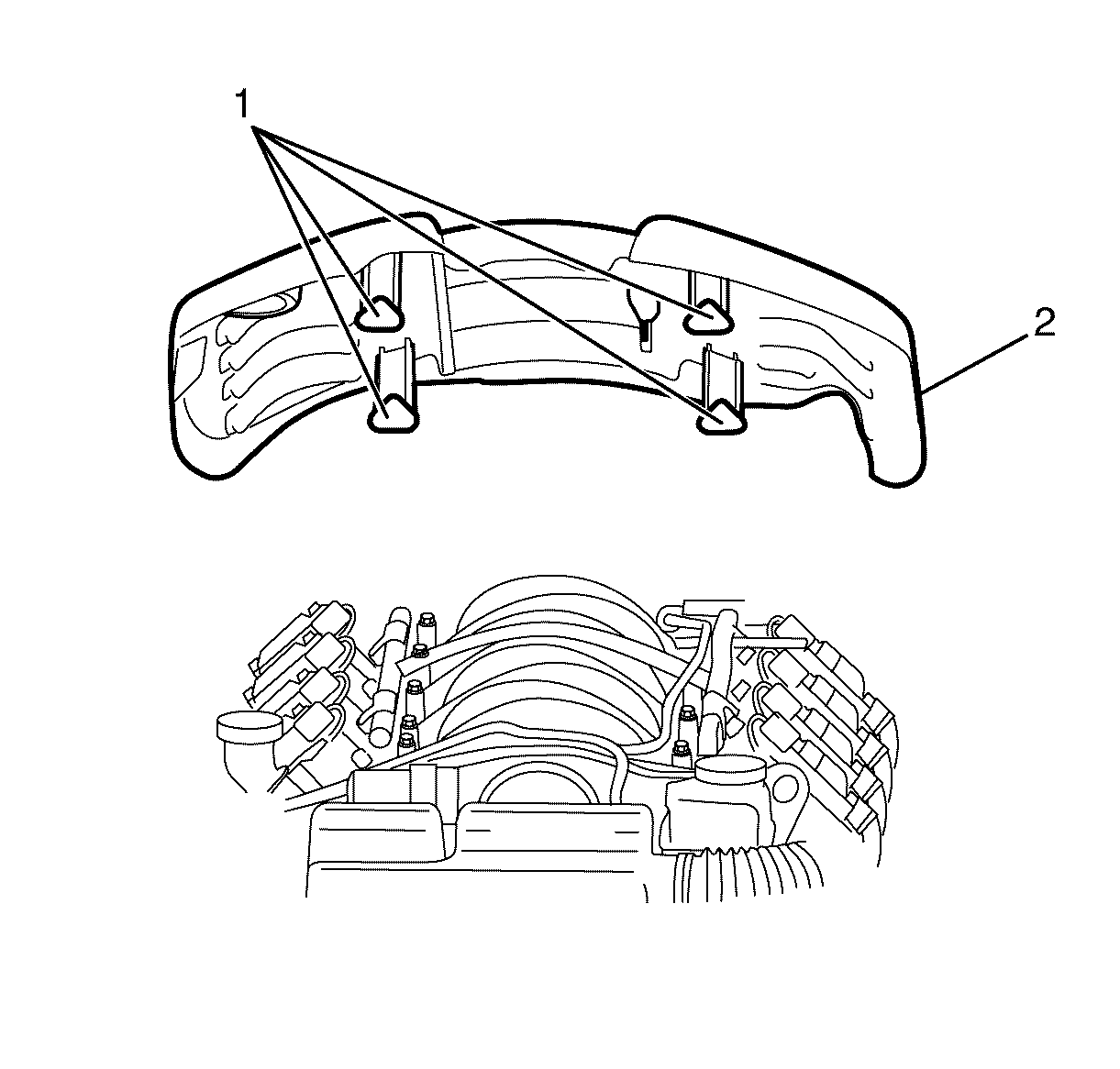
- Reposition and secure the heater hoses (1) away from the intake manifold (2).
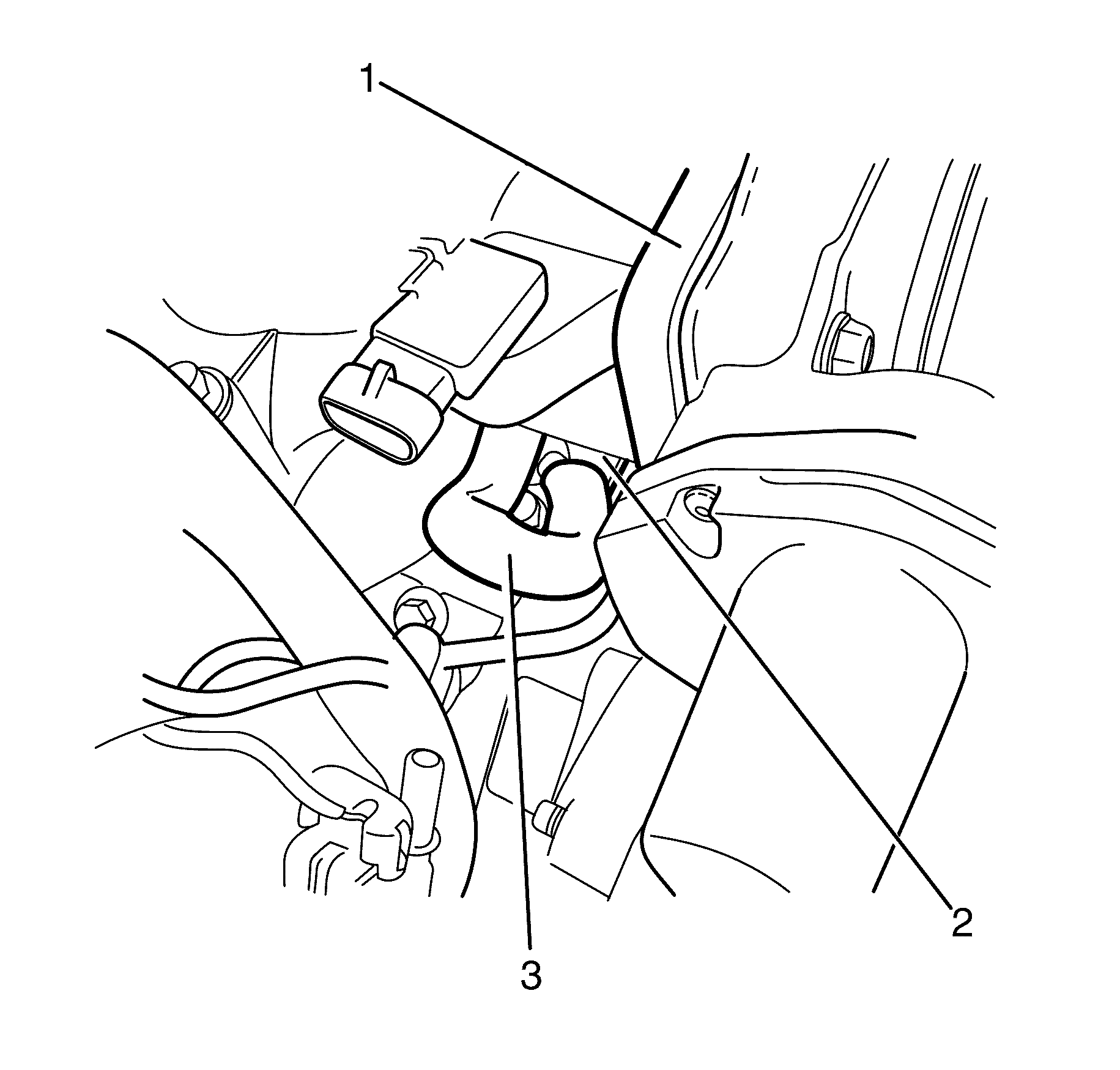
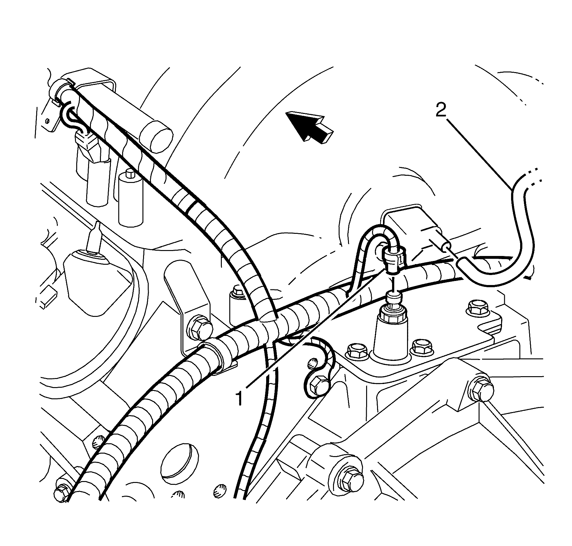
- Disconnect the fuel rail feed pipe (2) quick connect fitting. Refer to Metal Collar Quick Connect Fitting Service or Plastic Collar Quick Connect Fitting Service.
- Disconnect the throttle body to EVAP purge valve hose (3) from the EVAP purge valve (1).
- Disconnect the EVAP purge valve to fuel tank hose (2) from the EVAP purge valve (1).
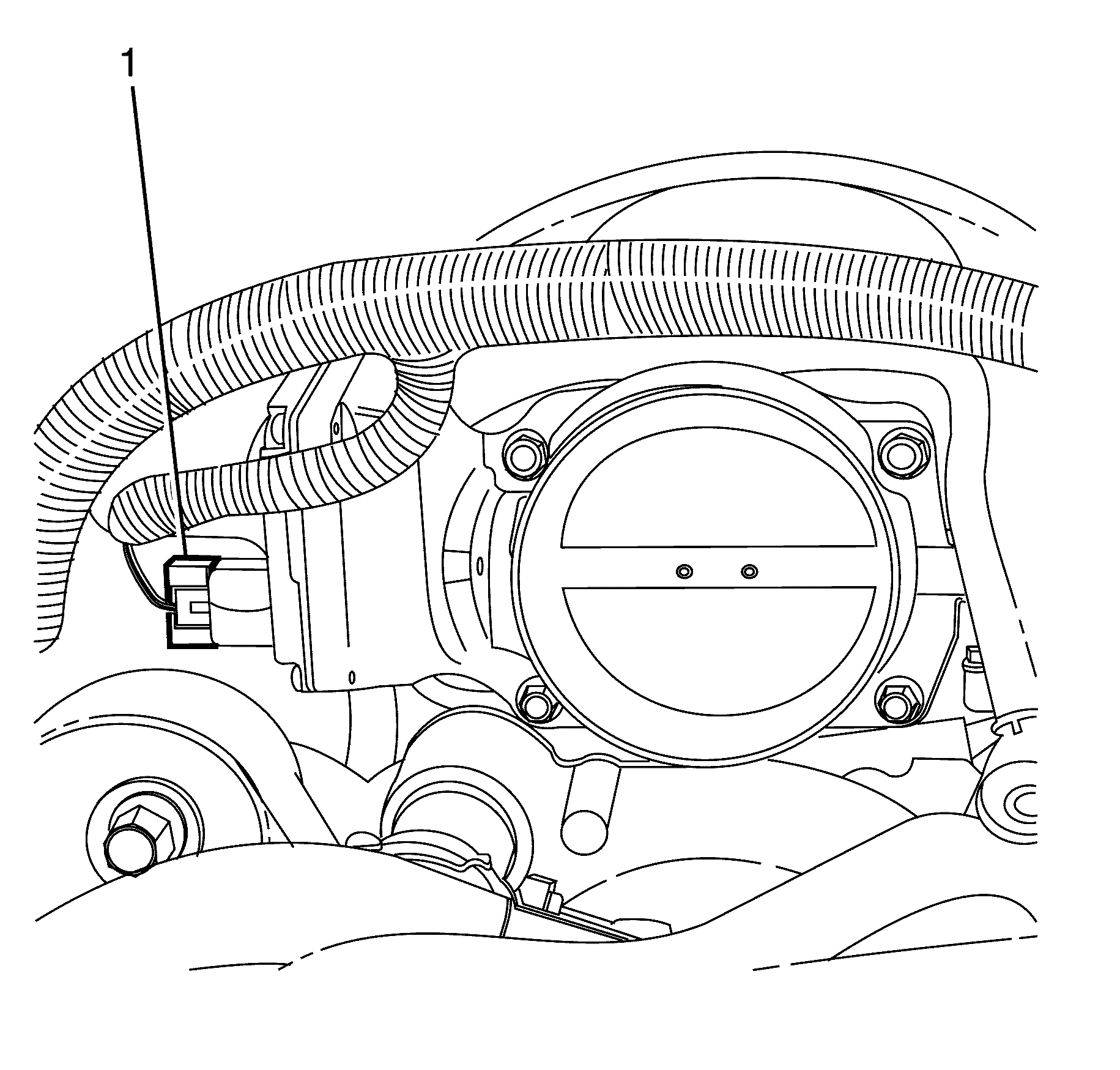
- Disconnect the electronic throttle body wiring harness connector (1).
- Disconnect the (PCV) Positive Crankcase Ventilation hose (3) from the intake manifold (1) and the valley cover (2).
- Disconnect the alternator wiring harness connector (1) from the alternator.
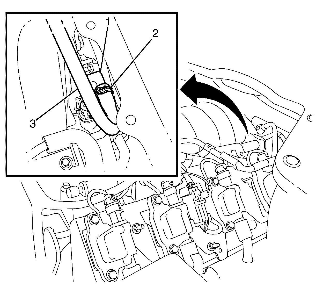
- Compress the vacuum brake booster hose retaining clamp (2) at the intake manifold vacuum port (1) and slide 50 mm (2 in) back along the vacuum brake booster hose (3).
- Disconnect the vacuum brake booster hose (3) from the intake manifold vacuum port (1).
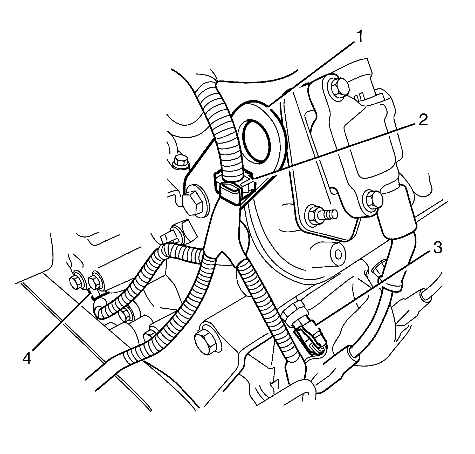
- Disconnect the oil pressure sensor wiring harness connector (1) from the oil pressure sensor.
- Disconnect the HVAC vacuum hose (2) from the intake manifold.
- Disconnect the camshaft position sensor connector (4) from the camshaft position sensor.
- Disconnect the coolant temperature sensor connector (3) from the coolant temperature sensor.
- Detach the wiring harness retaining clip (2) from the engine lifting bracket (1).
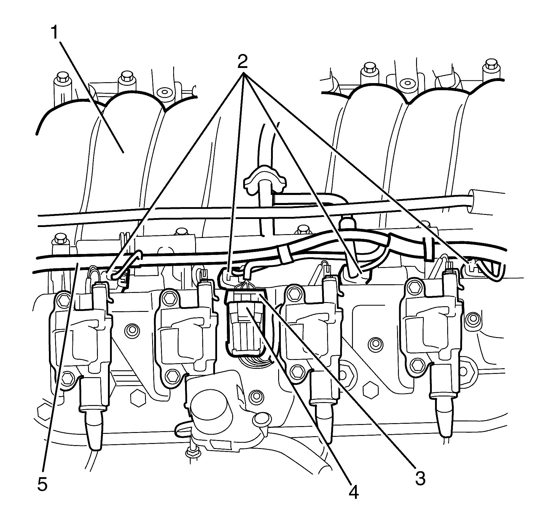
- Disconnect the left side fuel injector wiring harness connectors (2) from the fuel injectors.
- Remove the Connector Position Assurance (CPA) lock (4) from the left side ignition coil main connector (3).
- Disconnect the left side ignition coil main connector (3) from the ignition coil wiring harness.
- Reposition and secure the left side fuel injector wiring harness (5) away from the intake manifold (1).
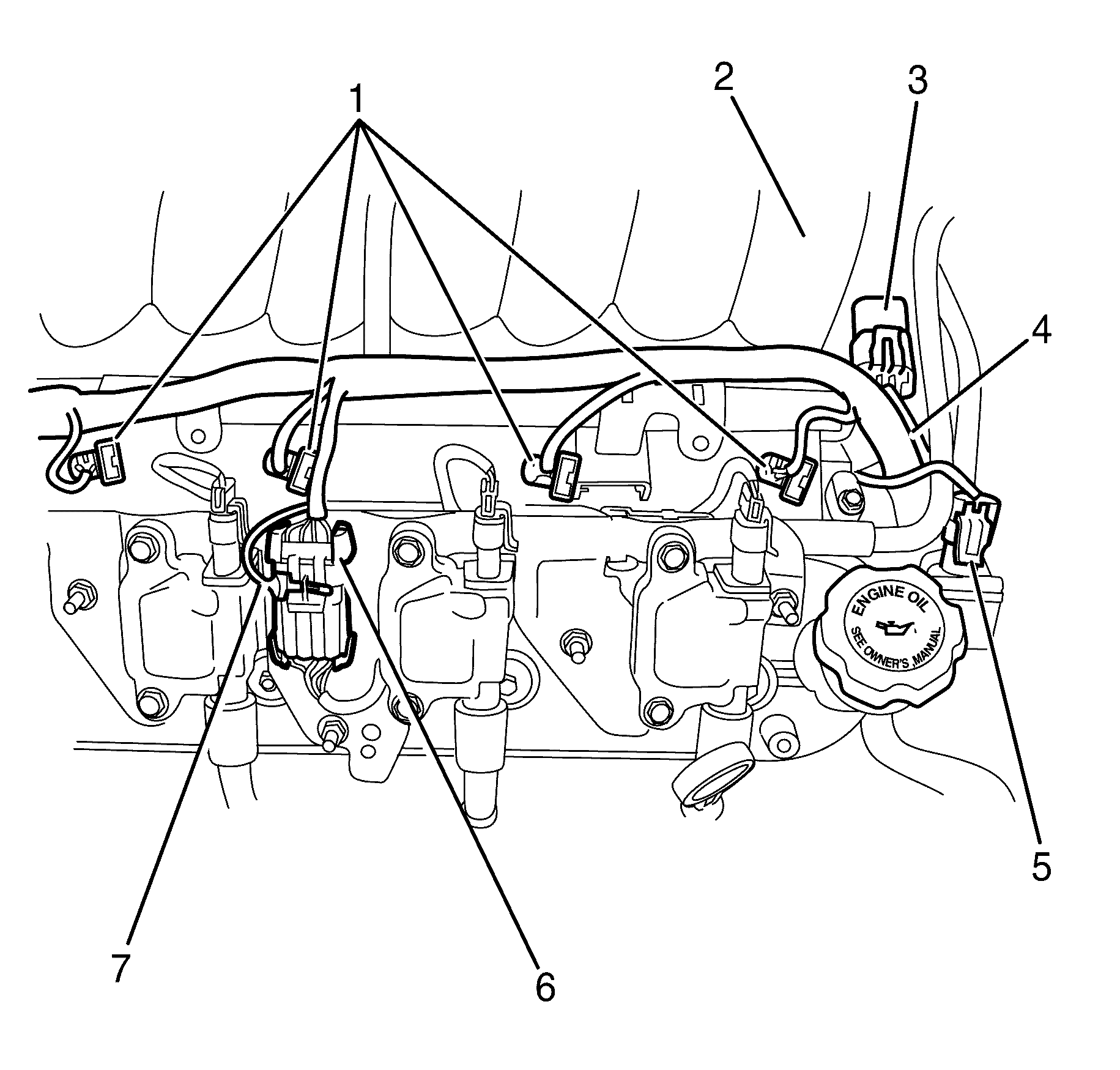
- Disconnect the right side fuel injector wiring harness connectors (1) from the fuel injectors.
- Remove the CPA lock (7) from the right side ignition coil main connector (6).
- Disconnect the right side ignition coil main connector (6) from the ignition coil wiring harness.
- Disconnect the canister purge valve (5) wiring harness connector.
- Disconnect the manifold absolute pressure (MAP) sensor wiring harness connector (3) from the MAP sensor.
- Reposition and secure the right side fuel injector wiring harness (4) away from the intake manifold (2).
- Remove the intake manifold. Refer to Intake Manifold Installation.
- Clean and inspect the intake manifold. Refer to Intake Manifold Cleaning and Inspection.
Important: The intake manifold, throttle body, fuel injection rail, and injectors may be removed as an assembly. If not servicing the individual components, remove the manifold as a complete assembly.
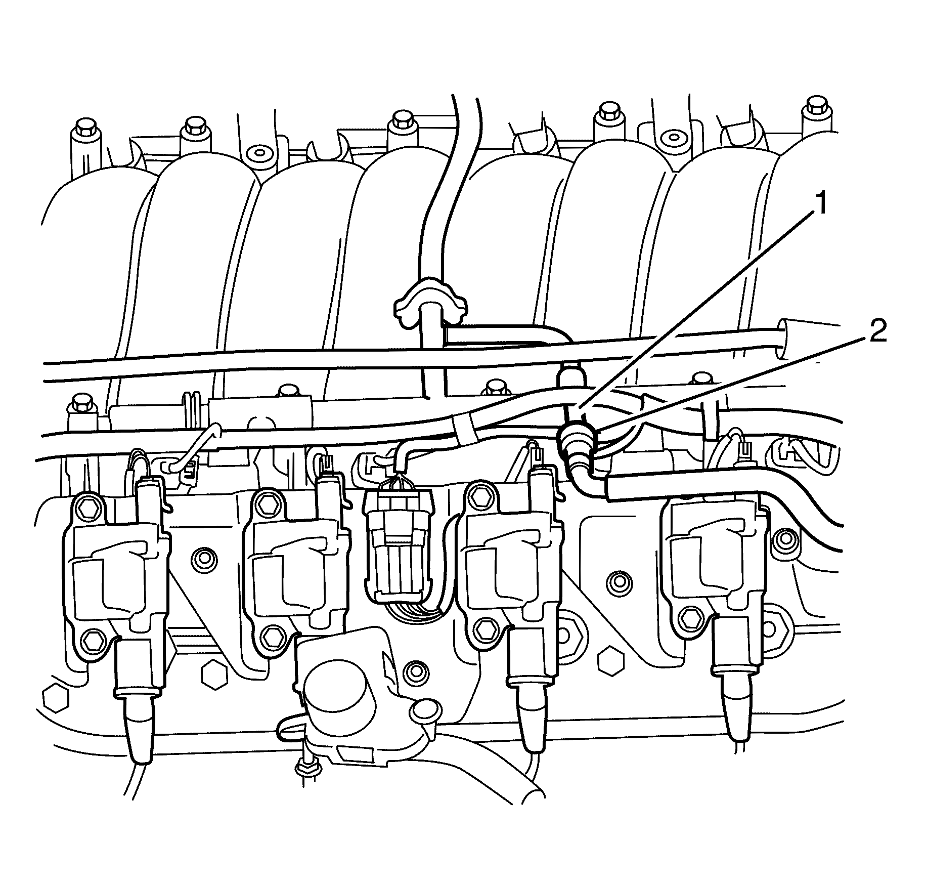
Important: Plug or cap the fuel feed pipe (2) and fuel rail tube (1) ends to prevent fuel leaks and/or contamination.
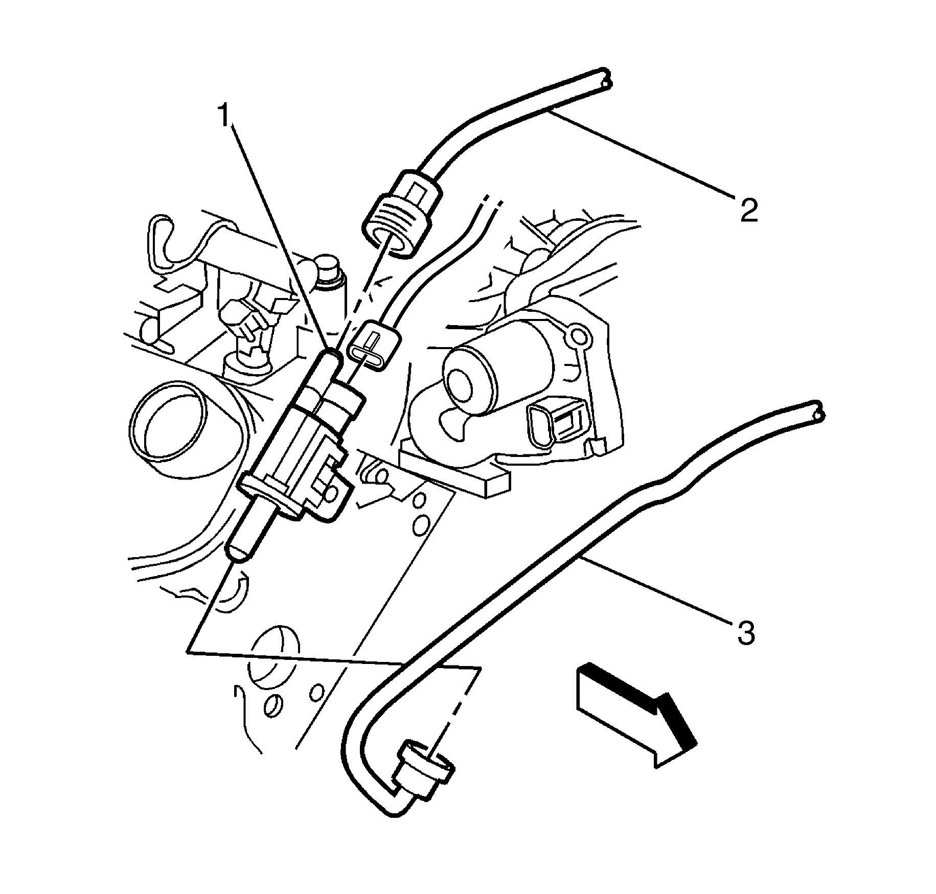
Important: Plug or cap the throttle body to EVAP purge valve hose (3) and EVAP purge valve (1) ends to prevent fuel leaks and/or contamination.
Important: Plug or cap the EVAP purge valve to fuel tank hose (2) and EVAP purge valve (1) ends to prevent fuel leaks and/or contamination.
Installation Procedure
- Install the intake manifold. Refer to Intake Manifold Installation.
- Position the right side fuel injector wiring harness (4) on the intake manifold (2).
- Connect the Manifold Absolute Pressure (MAP) sensor wiring harness connector (3) to the MAP sensor.
- Connect the canister purge valve wiring harness connector (5).
- Connect the right side ignition coil main connector (6) to the ignition coil wiring harness.
- Install the Connector Position Assurance (CPA) lock (7) from the right side ignition coil main connector (6).
- Connect the right side fuel injector wiring harness connectors (1) to the fuel injectors.
- Position the left side fuel injector wiring harness (5) back to its original location the intake manifold (1).
- Connect the left side ignition coil main connector (3) ignition coil wiring harness.
- Install the CPA lock (4) from the left side ignition coil main connector (3).
- Connect the left side fuel injector wiring harness connectors (2) to the fuel injectors.
- Connect the camshaft position sensor connector (4) to the camshaft sensor.
- Connect the coolant temperature sensor connector (3) to the coolant sensor.
- Attach the wiring harness retaining clip (2) to the engine lifting bracket (1).
- Connect the oil pressure sensor wiring harness connector (1) to the oil pressure sensor.
- Connect the HVAC vacuum hose (2) to the intake manifold.
- Connect the vacuum hose (3) to the intake manifold vacuum port (1).
- Compress the vacuum hose retaining clamp (2) and slide along the vacuum hose (3) to the correct location to secure the vacuum hose (3) to the intake manifold vacuum port (1).
- Connect the alternator wiring harness connector (1) to the alternator.
- Connect the PCV hose (3) to the intake manifold (1) and the valley cover (2).
- Connect the electronic throttle body wiring harness connector (1) to the throttle body.
- Remove the plug on the throttle body to EVAP purge valve hose (3) and EVAP purge valve (1) ends.
- Connect the throttle body to EVAP purge valve hose (3) to the EVAP purge valve (1).
- Remove the plug on the throttle body to the EVAP purge valve to fuel tank hose (2) and EVAP purge valve (1) ends.
- Connect the EVAP purge valve to fuel tank hose (2) to the EVAP purge valve (1).
- Remove the plug on the fuel feed pipe (2) and fuel rail tube (1) end.
- Connect the fuel rail feed pipe (2) quick connect fitting. Refer to Metal Collar Quick Connect Fitting Service or Plastic Collar Quick Connect Fitting Service.
- Position the heater hoses (1) correctly on the intake manifold (2).
- Install the air intake duct. Refer to Air Cleaner Inlet Duct Replacement.
- Fill the cooling system. Refer to Cooling System Draining and Filling.
- Connect the battery ground cable. Refer to Battery Negative Cable Disconnection and Connection.
- Run engine and check for leaks.
- Install the engine cover. Refer to Engine Cover Replacement.


