Special Tools
| • | J 8087 Cylinder Bore Gauge |
| • | J 42385-100 Head/Main Bolt Thread Repair Kit
|
For equivalent regional tools, refer to
Special Tools
Cleaning Procedure
Caution: Do not use a caustic solution to clean the aluminum engine block.
Note: When cleaning the engine block in a thermal type oven, do not exceed 232°C (450°F).
Clean the following components:
| • | Remove all sludge, dirt, or debris using a cleaning solvent or thermal type oven. Refer to
Cleanliness and Care. |
| • | Cylinder head bolt holes to remove threadlocking material |
| | Thread repair driver tool
J 42385-100 kit
may be used to clean the threads of old threadlocking material. |
Inspection Procedure
Inspect the following components:
| • | Cylinder walls for above acceptable scratches or gouging. |
| • | Cylinder bores for above acceptable ring ridge at the top of the cylinder. |
| • | Coolant jacket for cracks. |
| • | Valve lifter bores for above acceptable scoring or wear. |
| • | Crankshaft bearing webs for cracks. |
| • | Gasket sealing surfaces for above acceptable scratches or gouging. |
| • | Oil galleries for restrictions. |
| • | Threaded bolt holes for damaged threads. |
Measuring the Cylinder Deck for Distortion

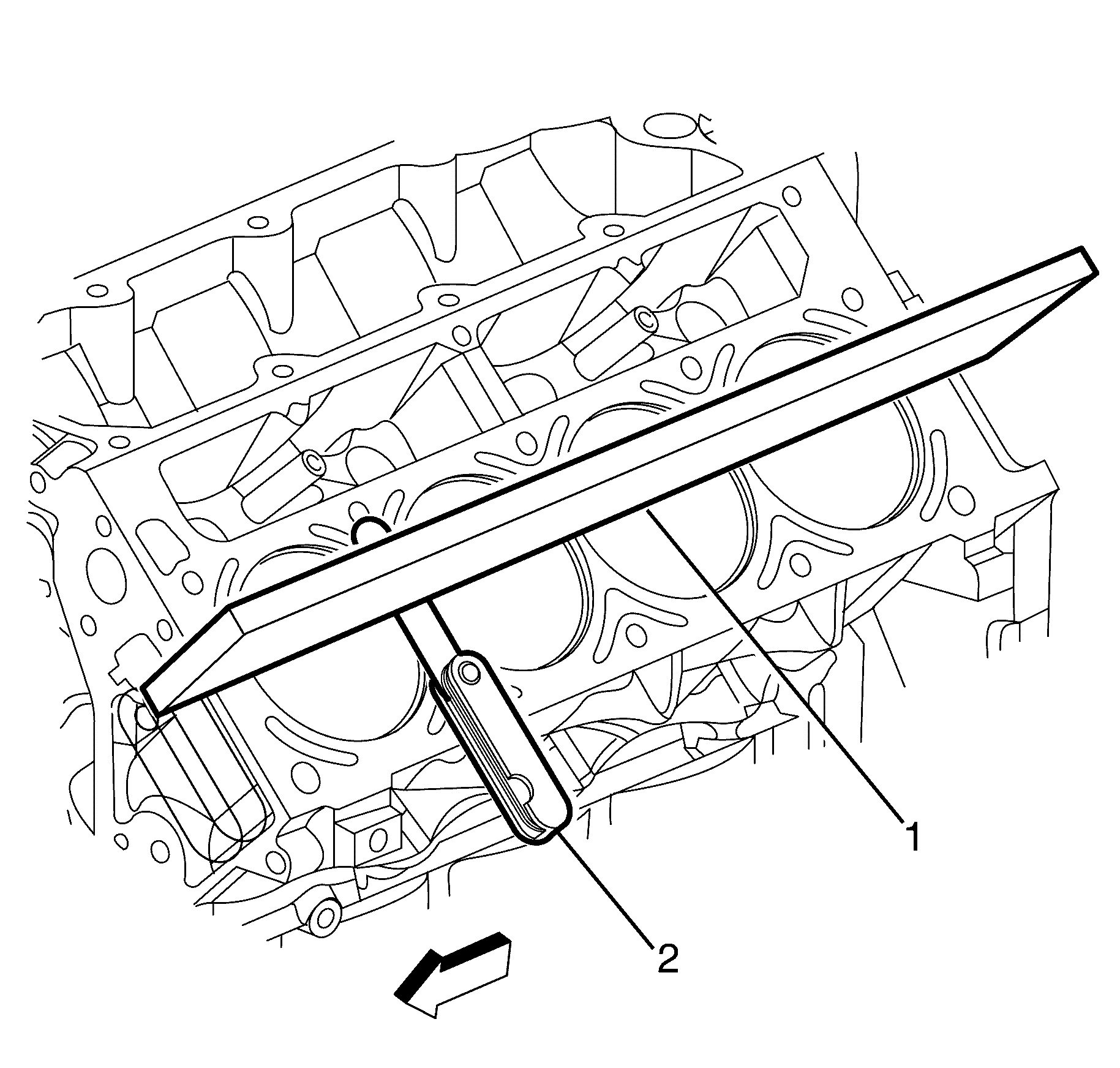
- Measure the cylinder block cylinder head deck using a straight edge (1) and feeler gauges (2).
- Check the flatness of the cylinder block and cylinder head deck surfaces. If the measurement is not within specification, the cylinder block must be replaced. machining is not recommended. Refer to
Engine Mechanical Specifications.
Measuring the Cylinder for Oversize
- Adjust the micrometer to a dimension slightly smaller than the bore size. Refer to
Engine Mechanical Specifications.

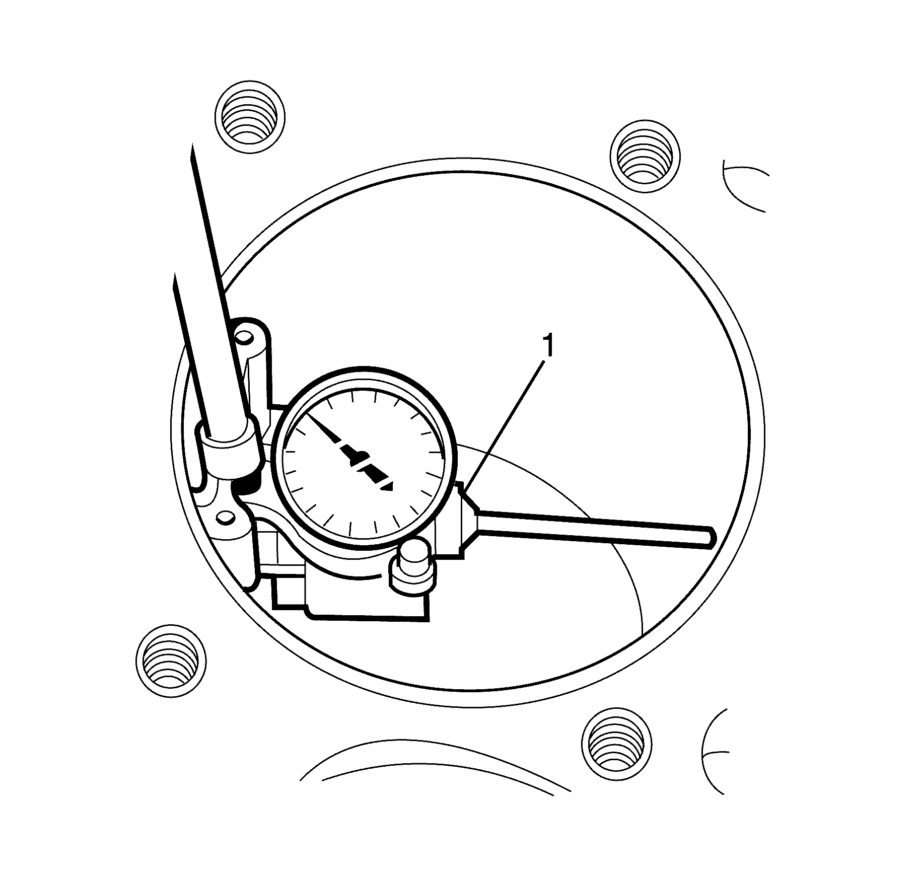
- Insert the
J 8087 gauge
(1) bore gauge into the micrometer and zero the bore gauge dial.
- Using the
J 8087 gauge
(1), measure the cylinder bore for oversize.
Slide the bore gauge up and down throughout the length of the cylinder bore. Check the bore
both parallel and perpendicular to the centre line of the crankshaft. A cylinder bore that exceeds the maximum diameter must be serviced with an oversized piston. Refer to
Engine Mechanical Specifications.

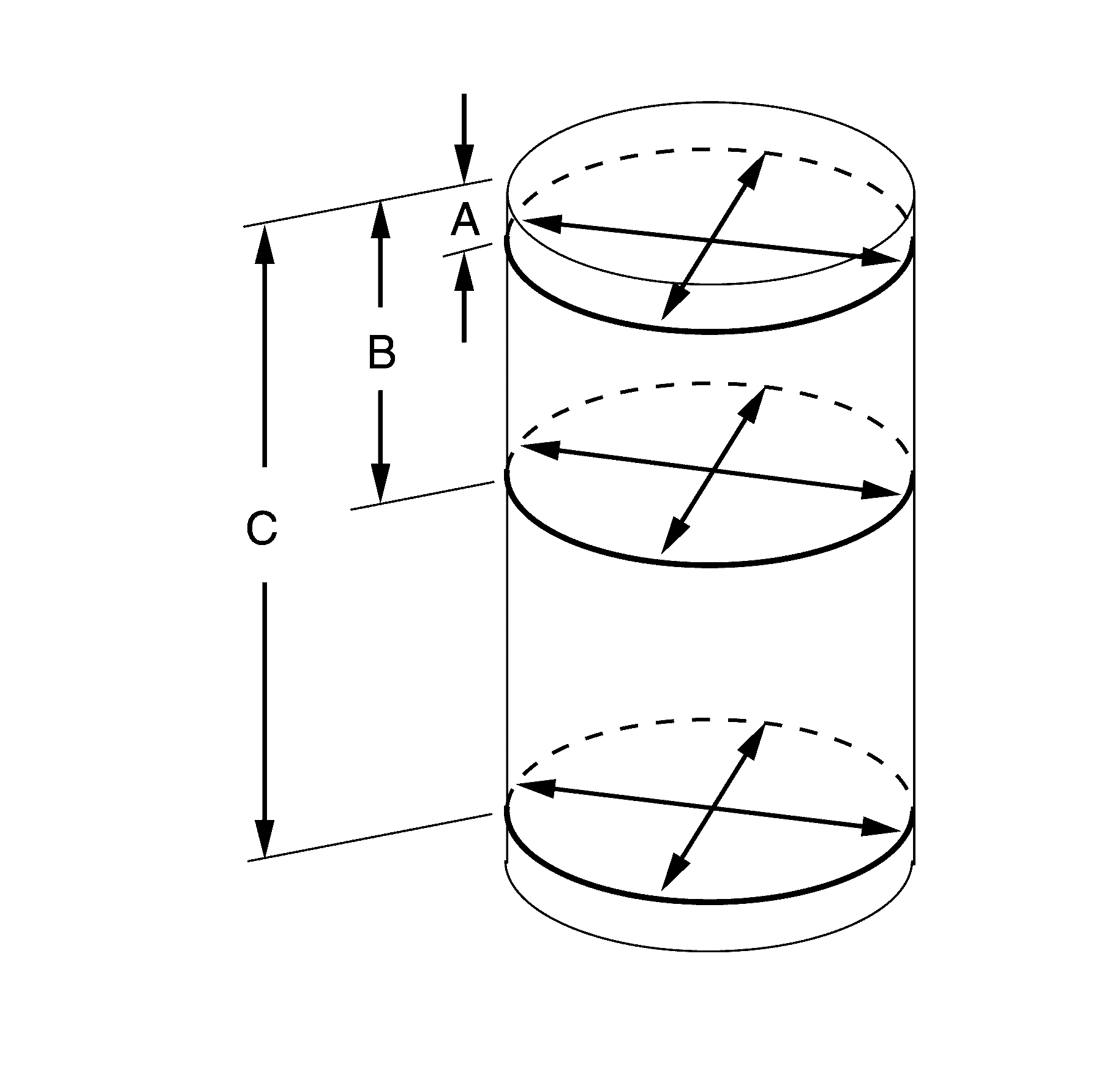
- Measure the bore at points (A, B and C), measure at these points both in line with and perpendicular to the crankshaft centre line.
| • | Point (A) is 9 mm from the cylinder head surfaces |
| • | Point (B) is 57 mm from the cylinder head surfaces |
| • | Point (C) is 127 mm from the cylinder head surfaces |
- Calculate the difference between the two measurements at each location, the results will indicate any out of round bore condition. A cylinder bore that exceeds the maximum out of round condition must be serviced with an oversized piston. Refer to
Engine Mechanical Specifications.


