Instrument Panel Upper Trim Pad Replacement RHD
Removal Procedure
- Disconnect the battery ground cable from the battery. Refer to Battery Negative Cable Disconnection and Connection .
- Disable the SIR system. Refer to SIR Disabling and Enabling .
- Remove the I/P compartment. Refer to Instrument Panel Compartment Replacement .
- Remove the trim panel - (I/P) Upper. Refer to Instrument Panel Upper Trim Panel Replacement .
- Remove the outer trim covers. Refer to Instrument Panel Outer Trim Cover Replacement .
- Remove the ventilation trim panel. Refer to Instrument Panel Side Trim Panel Replacement .
- Remove the trim plate - console side. Refer to Console Trim Plate Replacement .
- Remove the instrument panel trim panel. Refer to Instrument Panel Center Trim Panel Replacement .
- Remove the instrument cluster. Refer to Instrument Cluster Replacement .
- Remove the defroster grille. Refer to Defroster Grille Replacement .
- Remove the knee bolster. Refer to Knee Bolster Replacement .
- Remove the trim panel - I/P centre. Refer to Instrument Panel Center Trim Panel Replacement .
- Remove the I/P centre speaker. Refer to Radio Front Speaker Replacement .
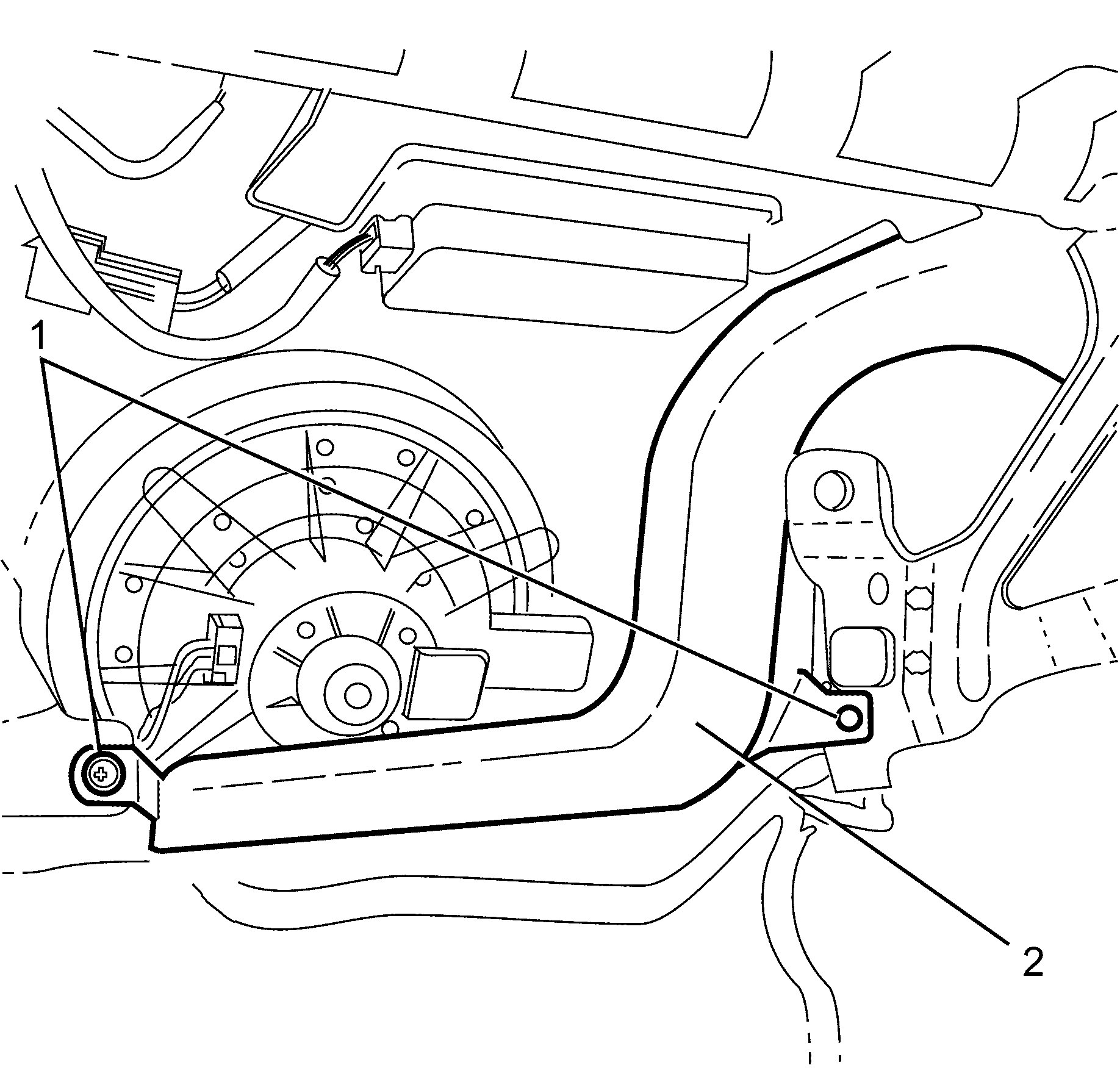
- Remove the lower air duct (2) retaining clips (1).
- Remove the lower air duct (2).
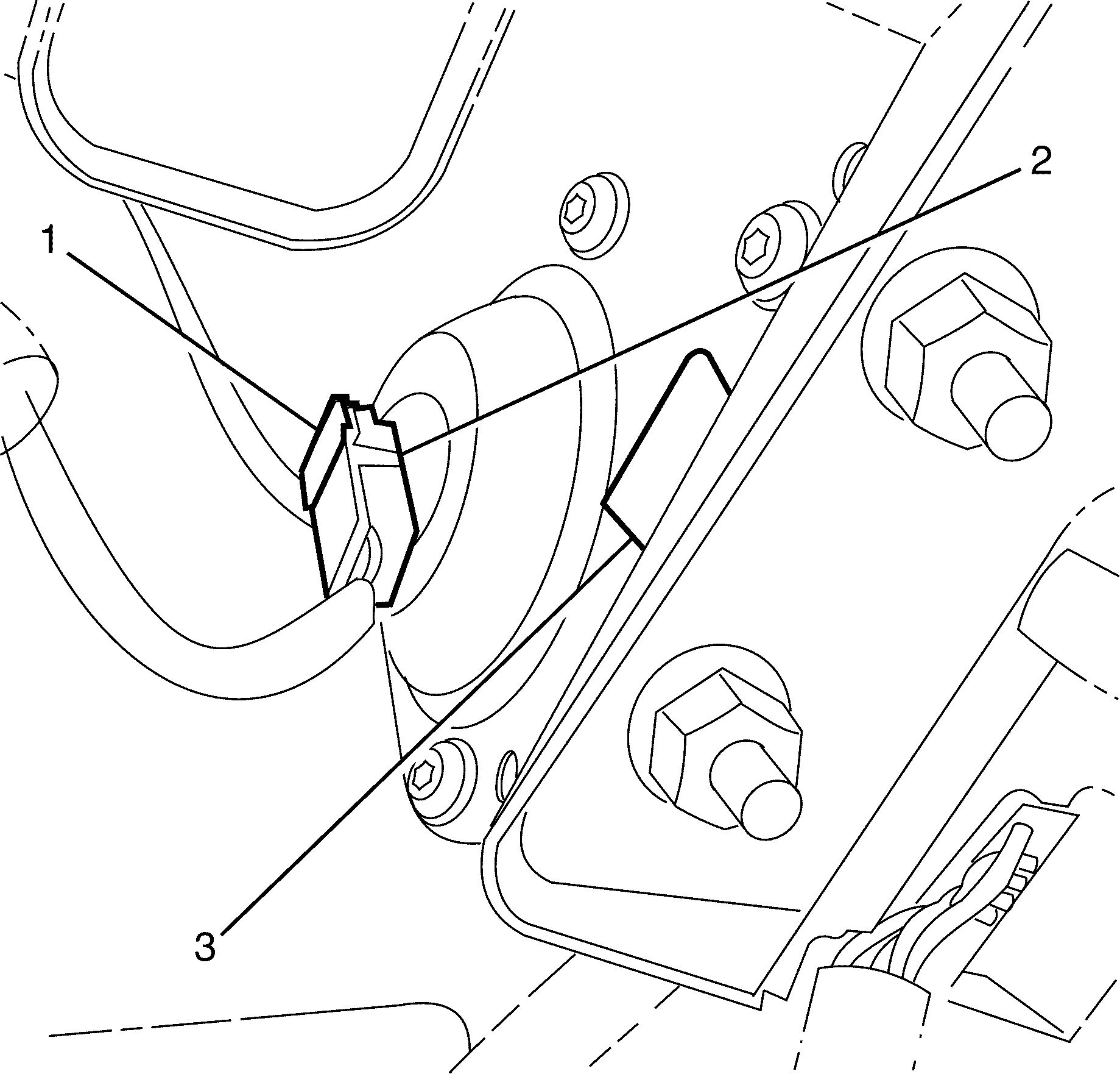
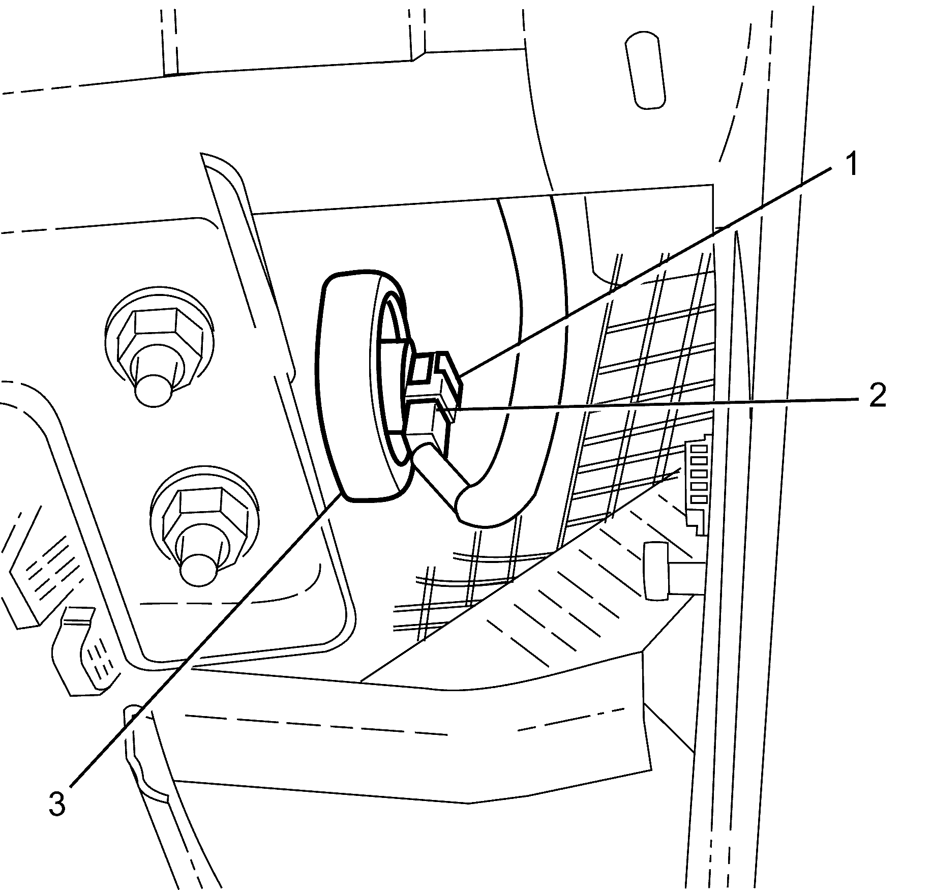
- Release the air bag (3) electrical connector retaining clip (1) and disconnect the electrical connector (2).
- Release the air bag (3) electrical connector retaining clip (1) and disconnect the electrical connector (2).
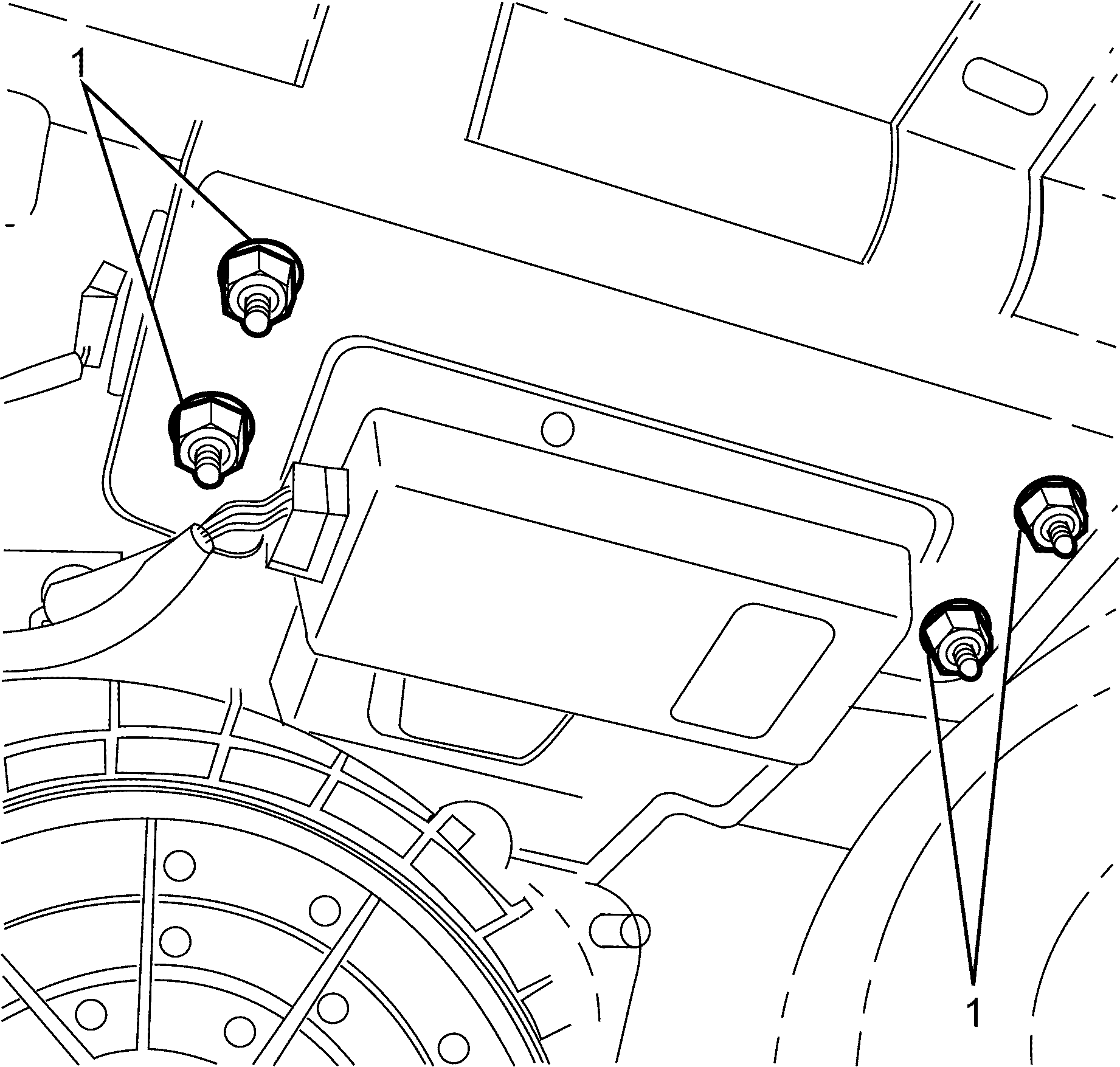
- Remove the air bag to I/P trim pad retaining nuts (1).
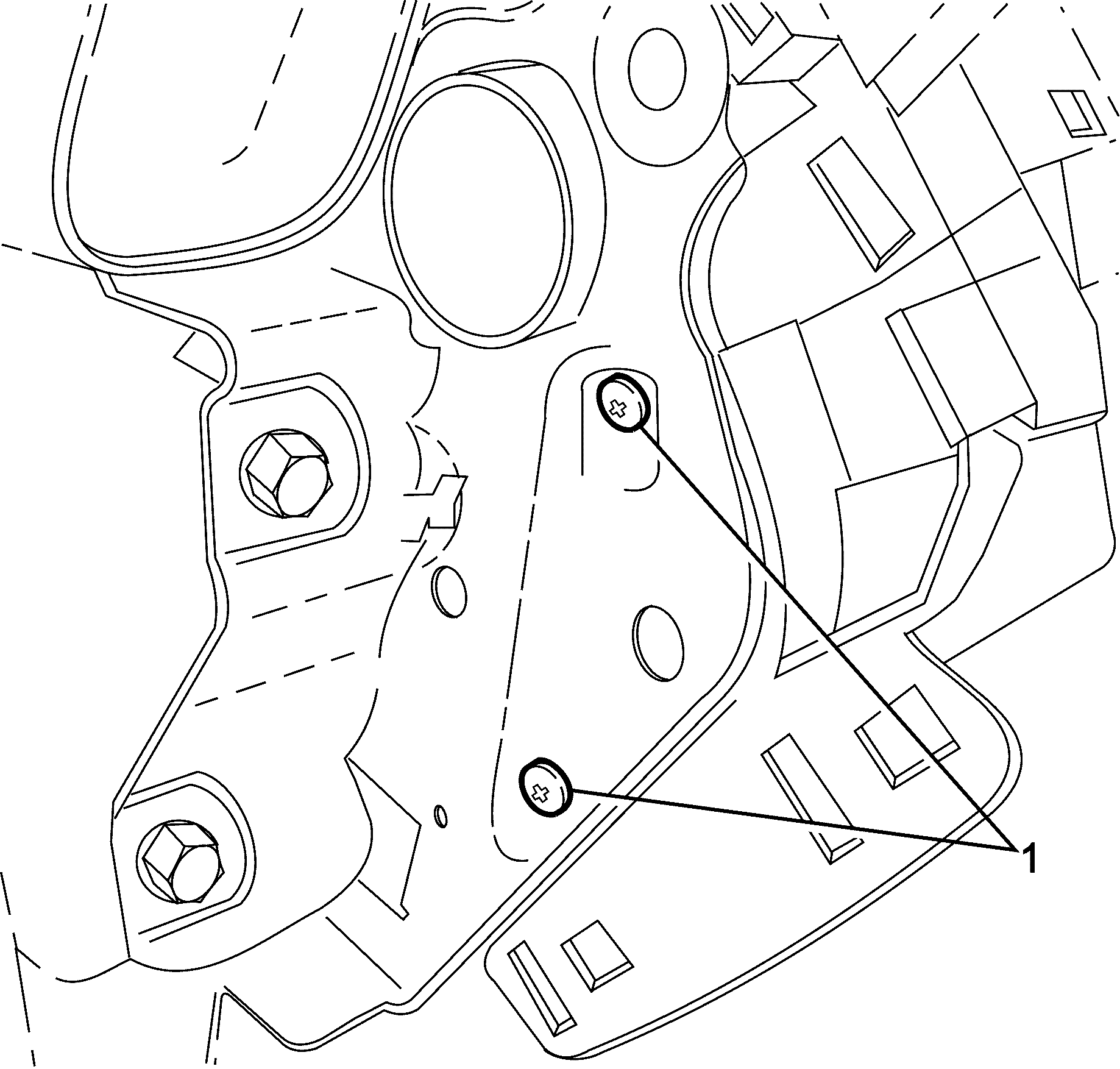
- Remove the I/P carrier to I/P pad outer retaining screws (1).
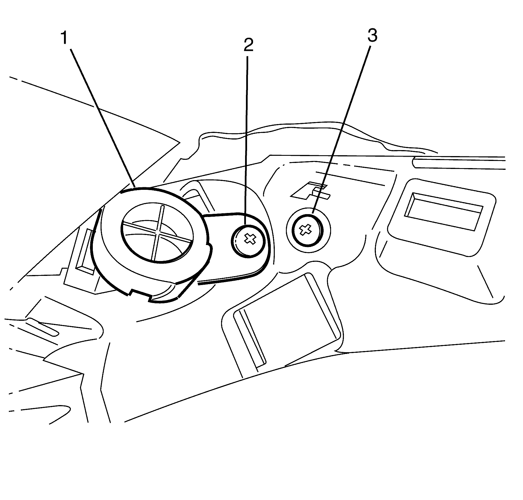
- Remove the left hand tweeter (1) to I/P pad retaining screw (2).
- Remove the I/P pad retaining screw (3).
- Disconnect the left hand tweeter (2) electrical connector (1).
- Remove the left hand tweeter (2).
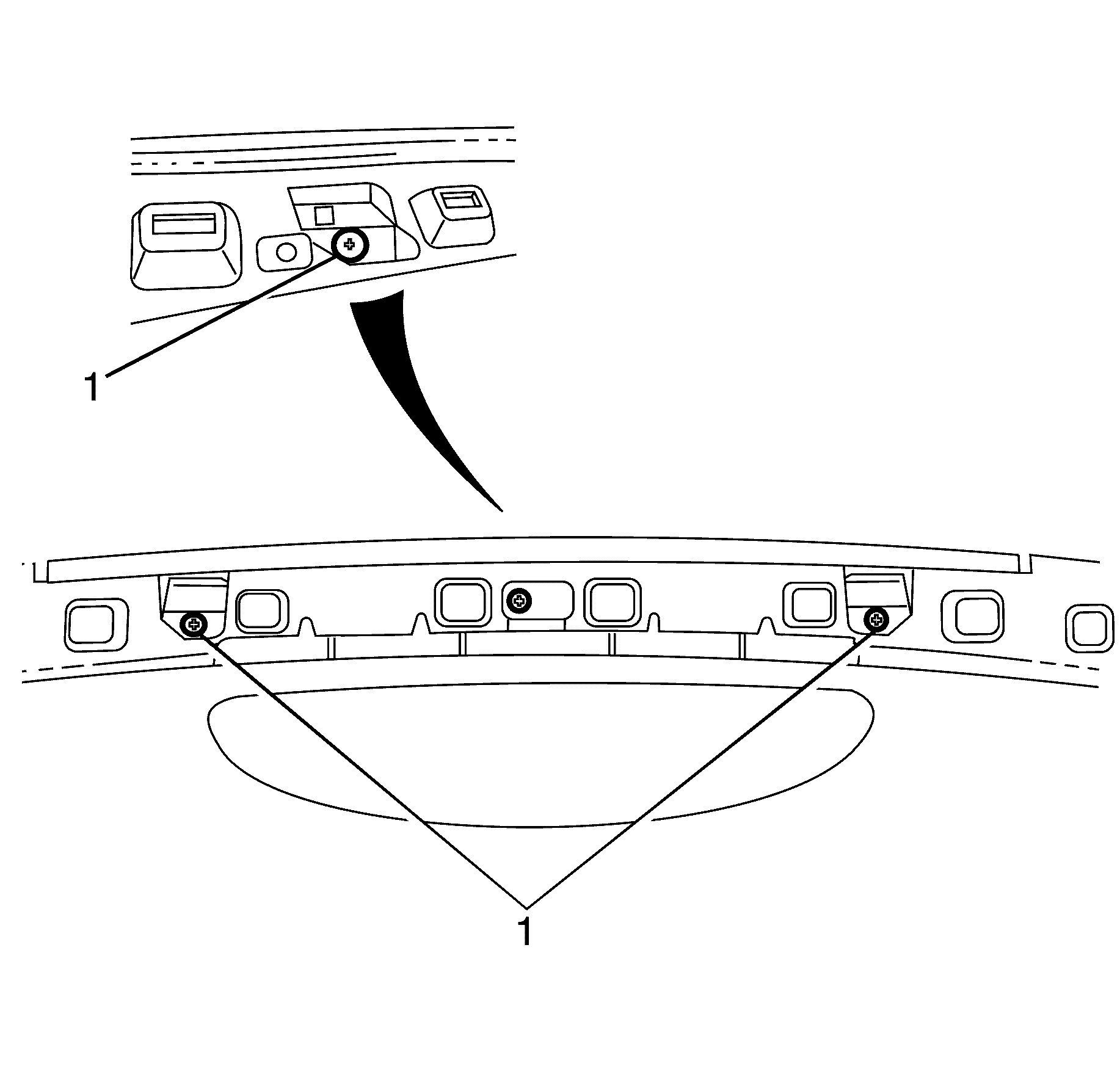
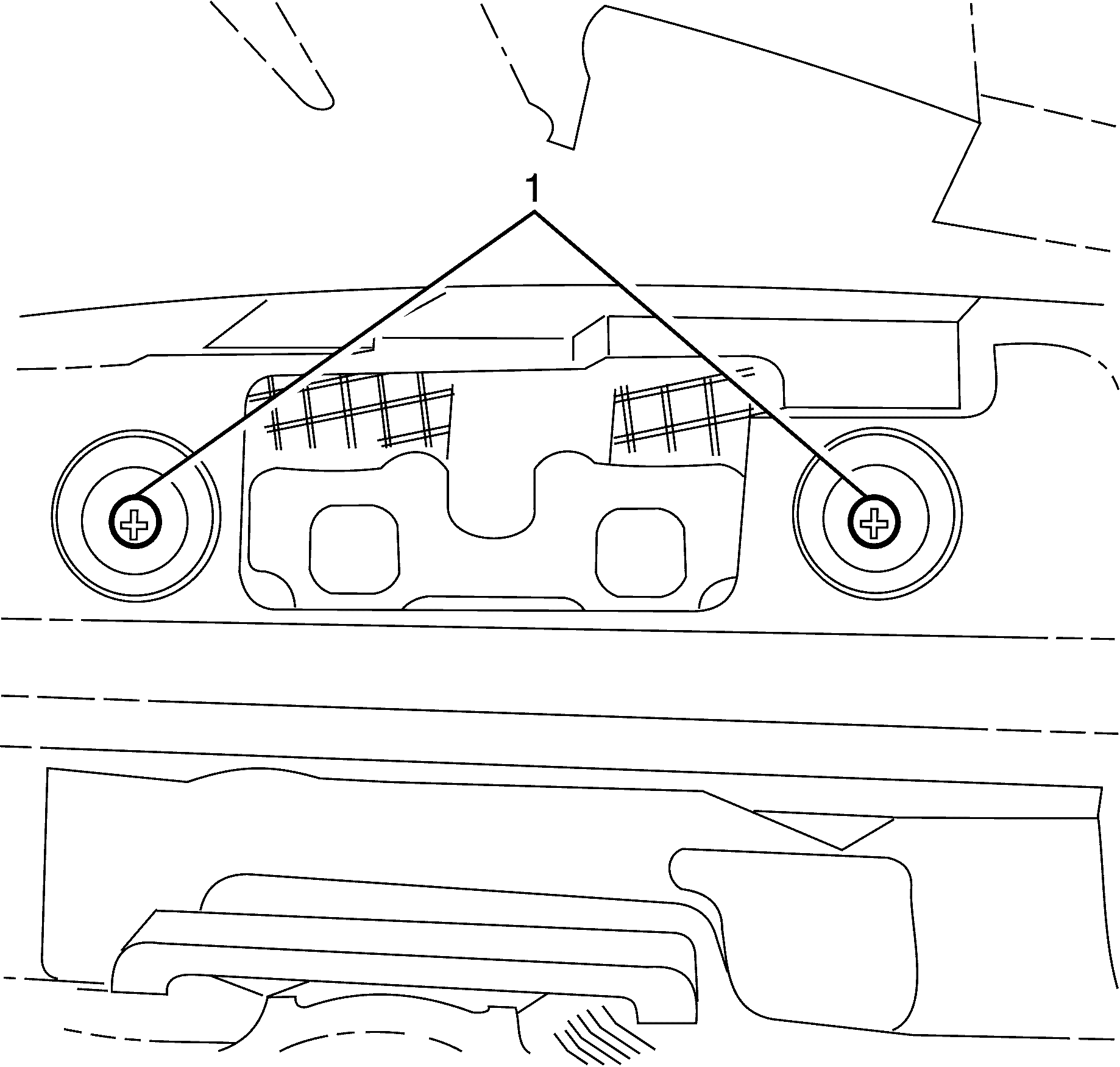
- Remove the top I/P pad to I/P carrier retaining screws (1).
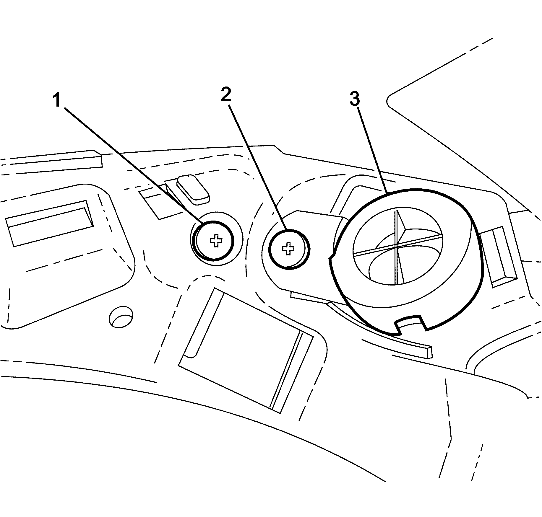
- Remove the right hand tweeter (3) to I/P pad retaining screw (2).
- Remove the I/P pad to I/P carrier retaining screw (1).
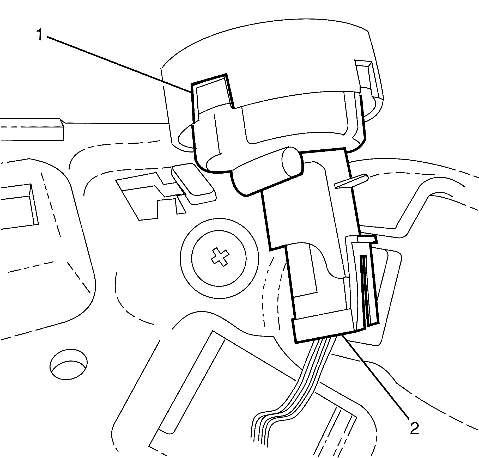
- Disconnect the right hand tweeter (1) electrical connector (2).
- Remove the right hand tweeter (1).
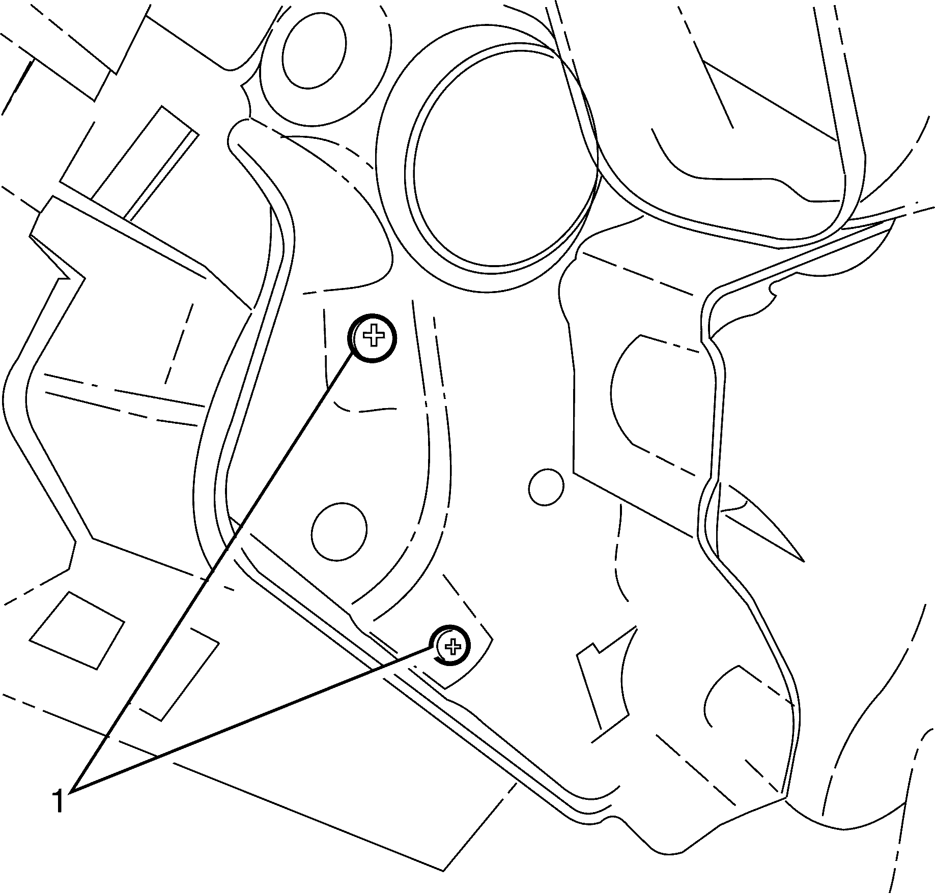
- Remove the I/P carrier to I/P pad outer retaining screws (1).
- Remove the Instrument cluster housing to I/P pad retaining screws (1).
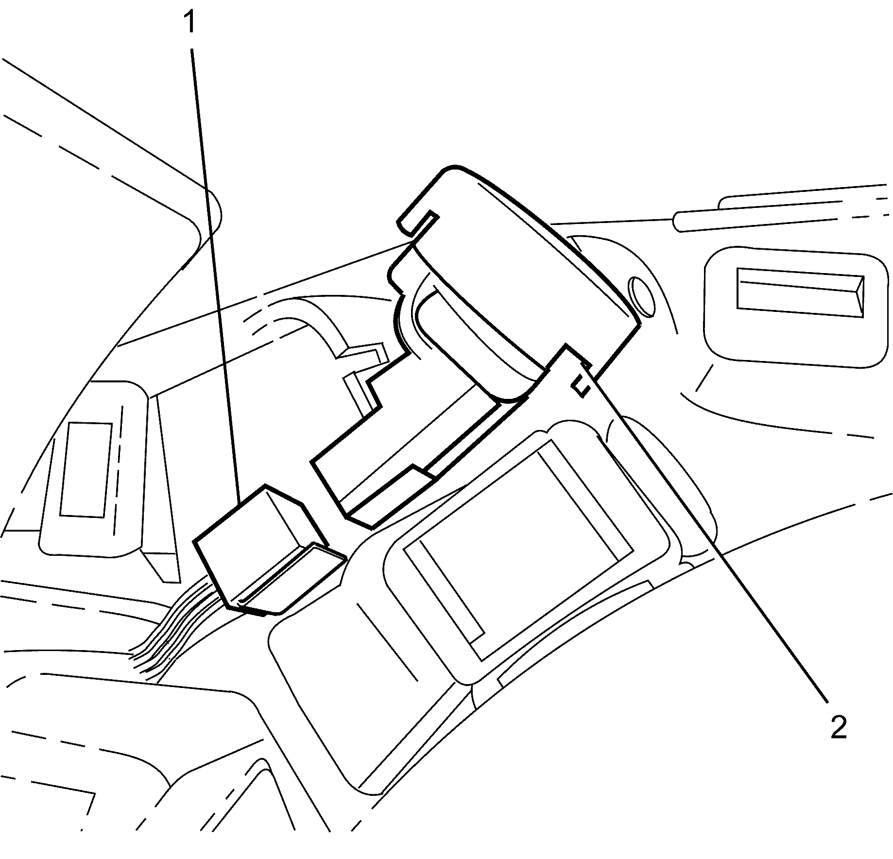
- Remove the centre console fresh air vent outlet (1).
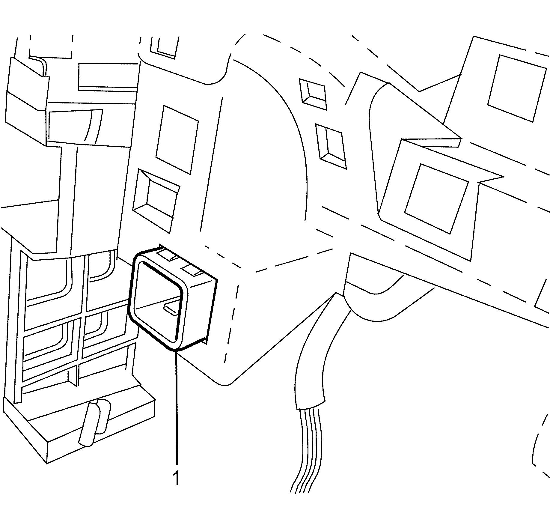
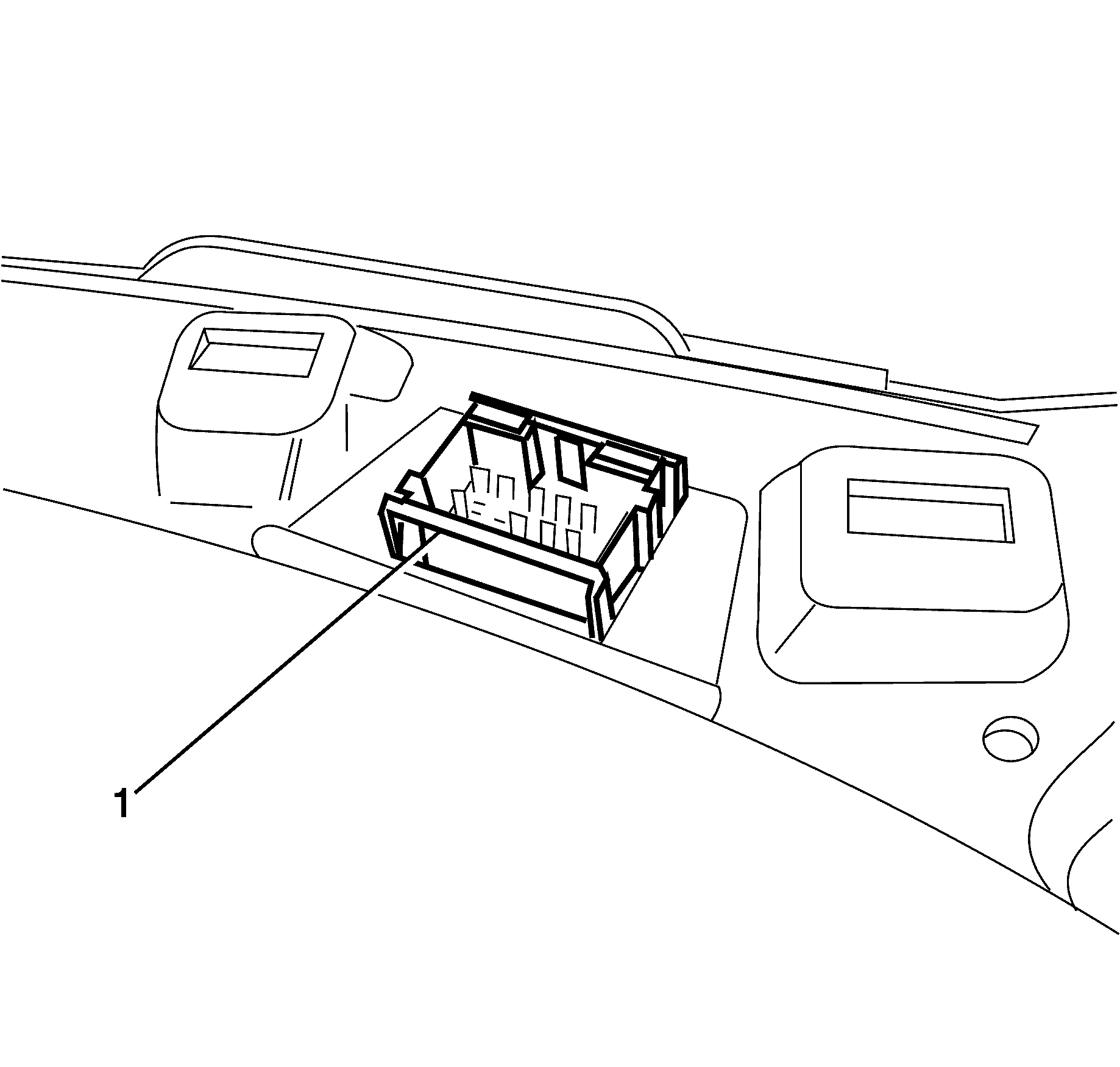
- Detach the headliner main wiring harness connector (1).
- Remove the I/P pad.
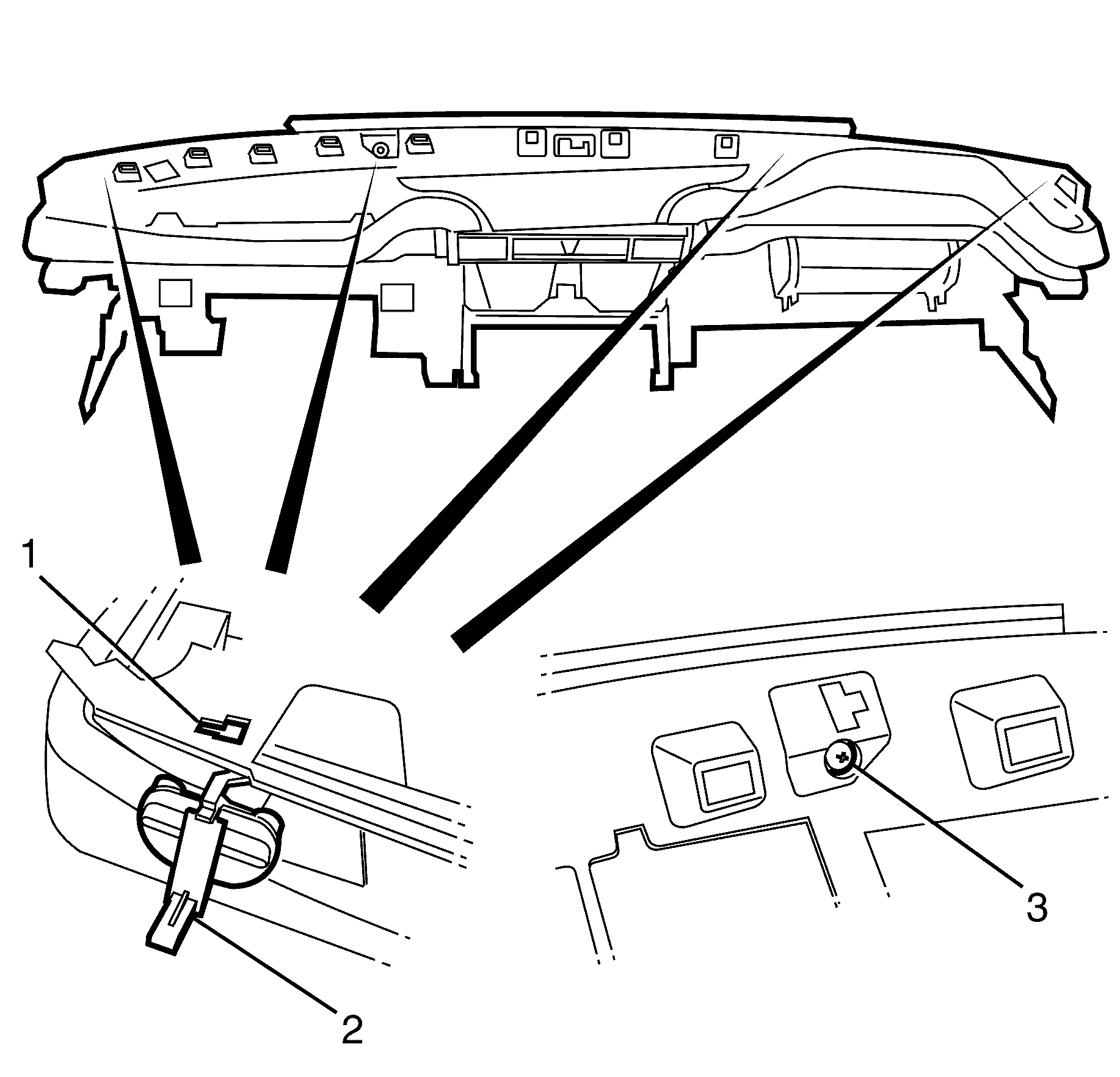
- Remove datum four pins from vehicle.
Caution: Refer to Battery Disconnect Caution in the Preface section.
| • | Trim Panel - (I/P) Upper : (with secondary information centre SIC) |
| • | Trim Panel - (I/P) Upper : (with multi function display) |
Notice: Refer to General Repair Instructions in the Preface section.
Important: The removal of the I/P pad must be done with the aid if an assistant under no circumstances must it be removed by one person.
Installation Procedure
- Place the I/P pad on a clean and suitable work surface.
- Install the four datum pins (2) to the I/P pad (1).
- Secure the datum pins (2) using the datum pin retaining screws (3).
- Install the I/P pad to the vehicle.
- Secure the headliner main wiring harness connector (1).
- Install the centre console fresh air vent outlet (1).
- Install the Instrument cluster to I/P pad retaining screws (1).
- Install the I/P carrier to I/P pad outer retaining screws (1).
- Connect the right hand tweeter (1) electrical connector (2).
- Install the right hand tweeter (2).
- Install the right hand tweeter (3) to I/P pad retaining screw (2).
- Install the I/P pad to I/P carrier retaining screw (1).
- Install the top I/Ppad to I/P carrier retaining screws (1).
- Connect the left hand tweeter (2) electrical connector (1).
- Install the left hand tweeter (2).
- Install the left hand tweeter (1) to I/P pad retaining screw (2).
- Install the I/P pad retaining screw (3).
- Install the I/P carrier to I/P pad outer retaining screws (1).
- Install the air bag to I/P trim pad retaining nuts (1).
- Install the air bag (3) electrical connector (2) and secure by inserting the electrical connector retaining clip (1).
- Install the air bag (3) electrical connector (2) and secure by inserting the electrical connector retaining clip (1).
- Install the lower air duct (2).
- Install the lower air duct (2) retaining clip (1).
- Install the I/P centre speaker. Refer to Radio Front Speaker Replacement .
- Install the trim panel - I/P centre. Refer to Instrument Panel Center Trim Panel Replacement .
- Install the knee bolster. Refer to Knee Bolster Replacement .
- Install the defroster grille. Refer to Defroster Grille Replacement .
- Instal the instrument cluster. Refer to Instrument Cluster Replacement .
- Install the instrument panel trim panel. Refer to Instrument Panel Center Trim Panel Replacement .
- Install the trim plate - console side. Refer to Console Trim Plate Replacement .
- Install the ventilation trim panel. Refer to Instrument Panel Side Trim Panel Replacement
- Install the outer trim covers. Refer to Instrument Panel Outer Trim Cover Replacement .
- Install the trim panel - (I/P) Upper. Refer to Instrument Panel Upper Trim Panel Replacement .
- Install the I/P compartment. Refer to Instrument Panel Compartment Replacement .
- Enable the SIR system. Refer to SIR Disabling and Enabling .
- Connect the battery ground cable to the battery. Refer to Battery Negative Cable Disconnection and Connection .
- Test all electrical components for correct operation.
Tighten
Tighten the screws (3) to 2 N·m (18 lb in).
Important: Before installing the I/Ppad, ensure all electrical connectors are correctly positioned.

Headliner main harness connector: If difficulty is found securing the harness connector to the I/P pad, bring the I/P pad towards the steering wheel to gain access.

Notice: Refer to Fastener Notice in the Preface section.

Tighten
Tighten the screws (1) to 2 N·m (18 lb in).
Notice: Refer to Fastener Notice in the Preface section.

Tighten
Tighten the screws (1) to 2 N·m (18 lb in).

Notice: Refer to Fastener Notice in the Preface section.

Tighten
Tighten the screws (2) to 2 N·m (18 lb in).
Tighten
Tighten the screws (1) to 2 N·m (18 lb in).
Notice: Refer to Fastener Notice in the Preface section.

Tighten
Tighten the screws (1) to 2 N·m (18 lb in).

Notice: Refer to Fastener Notice in the Preface section.

Tighten
Tighten the screw (2) to 2 N·m (18 lb in).
Tighten
Tighten the screws (3) to 2 N·m (18 lb in).
Notice: Refer to Fastener Notice in the Preface section.

Tighten
Tighten the screws (1) to 2 N·m (18 lb in).
Notice: Refer to Fastener Notice in the Preface section.

Tighten
Tighten the nuts to 16 N·m (12 lb ft).


| • | Trim Panel - (I/P) Upper : (with secondary information centre SIC) |
| • | Trim Panel - (I/P) Upper : (with multi function display) |
