Roof Panel Rear Applique Replacement Except HSV Maloo
Removal Procedure
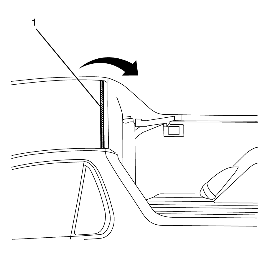
- Using a suitable tool detach the body lock pillar trim to rear header trim retaining clip (1).
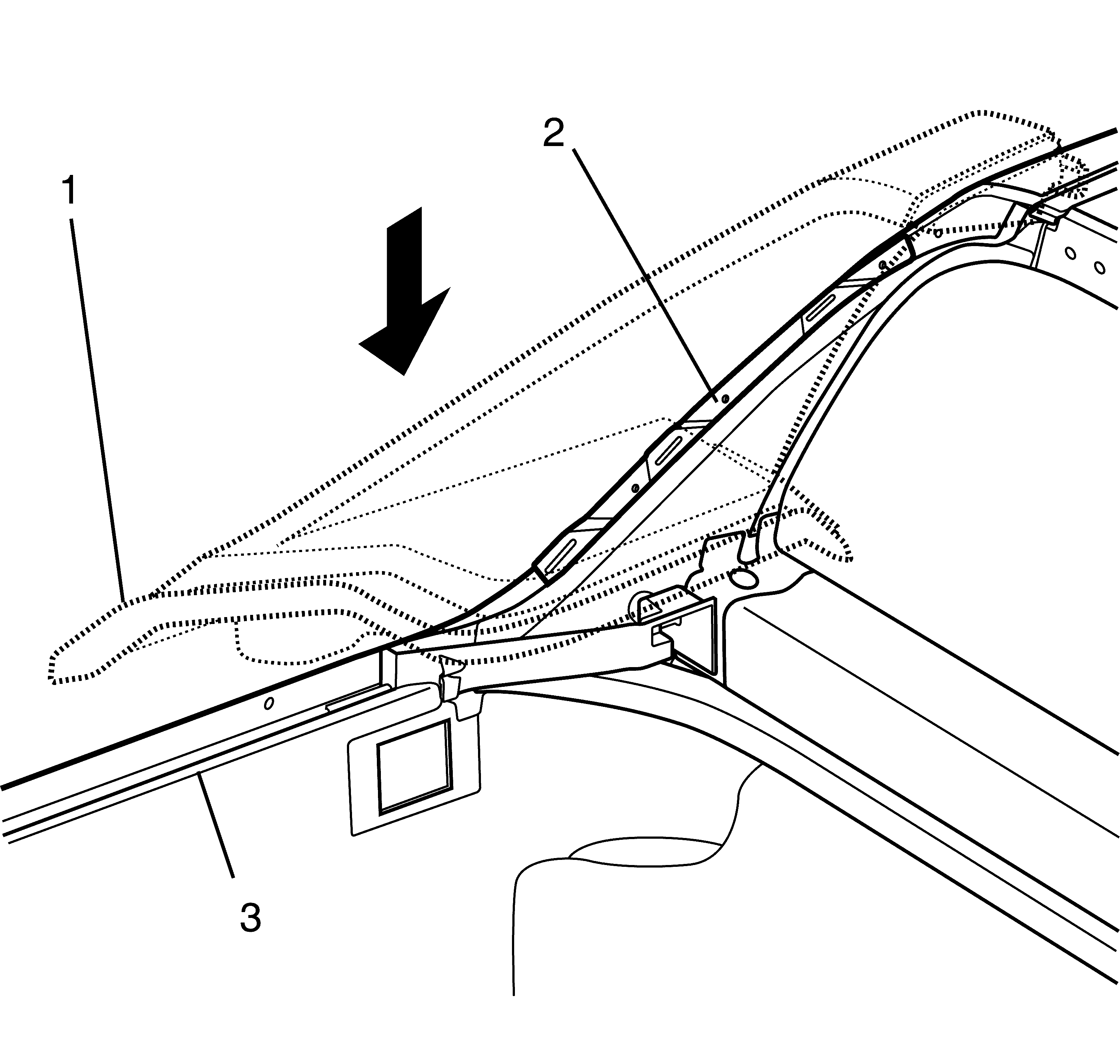
- Using a suitable tool remove the rear header trim (2) from the adhesive (1) on the roof panel.
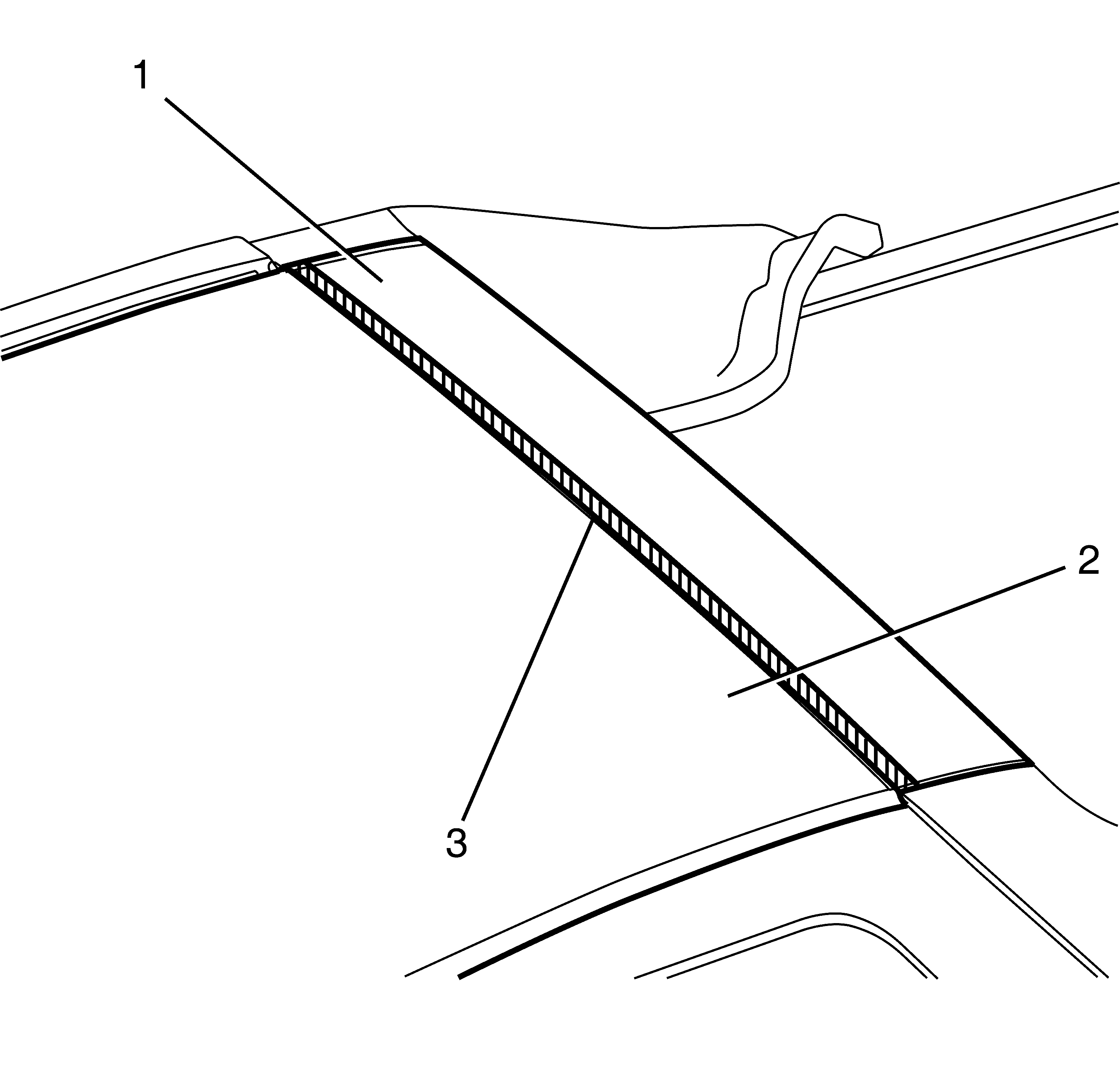
- Disengage the roof panel to rear header trim retaining clips (1).
- Detach the rear header trim (2) from the roof panel (3).
- If fitted with a high mounted stop lamp, disconnect the electrical connector (1).
- If fitted with a high mounted stop lamp, remove the high mounted stop lamp from the rear header trim. Refer to High Mount Stop Lamp Replacement .
- Remove any remaining adhesive (1) from the roof panel and rear header trim and clean the surface with a suitable cleaning solution using a lint free cloth.
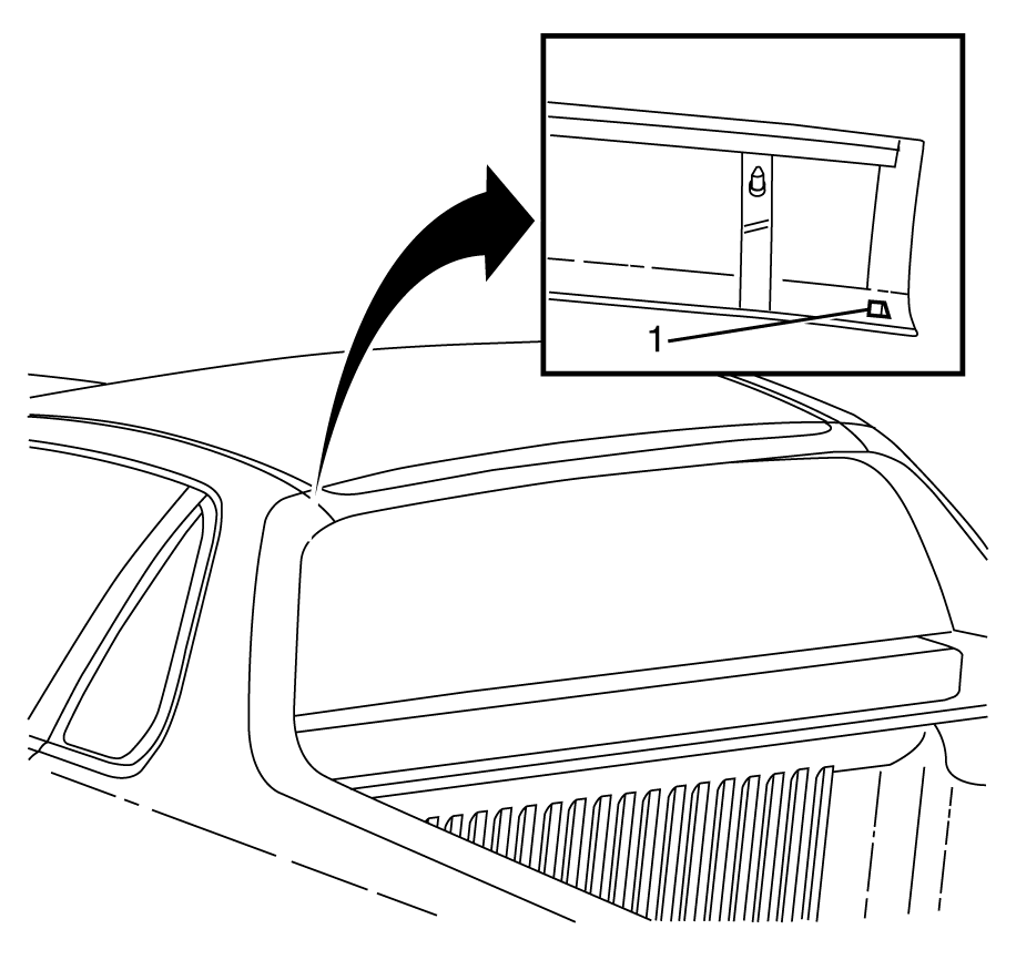
Important: Protect the paint and body work with tape or a clean cloth. Failure to do so may result in damage to the paint work.
Important: Take care not to damage the paint work when prying the rear header trim from the roof panel.
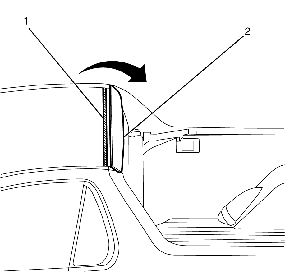
Important: To assist in the removal of the rear header trim (2), warm the front edge of the rear header trim with a heat gun.
Important: Take care not to damage the paint work when prying the rear header trim from the roof panel.
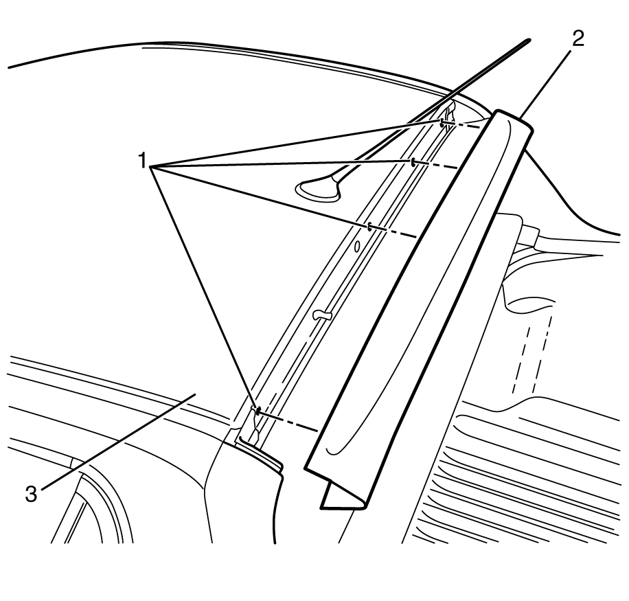
Important: If a high mounted stop lamp is fitted take care not to cause damage to the wiring harness.
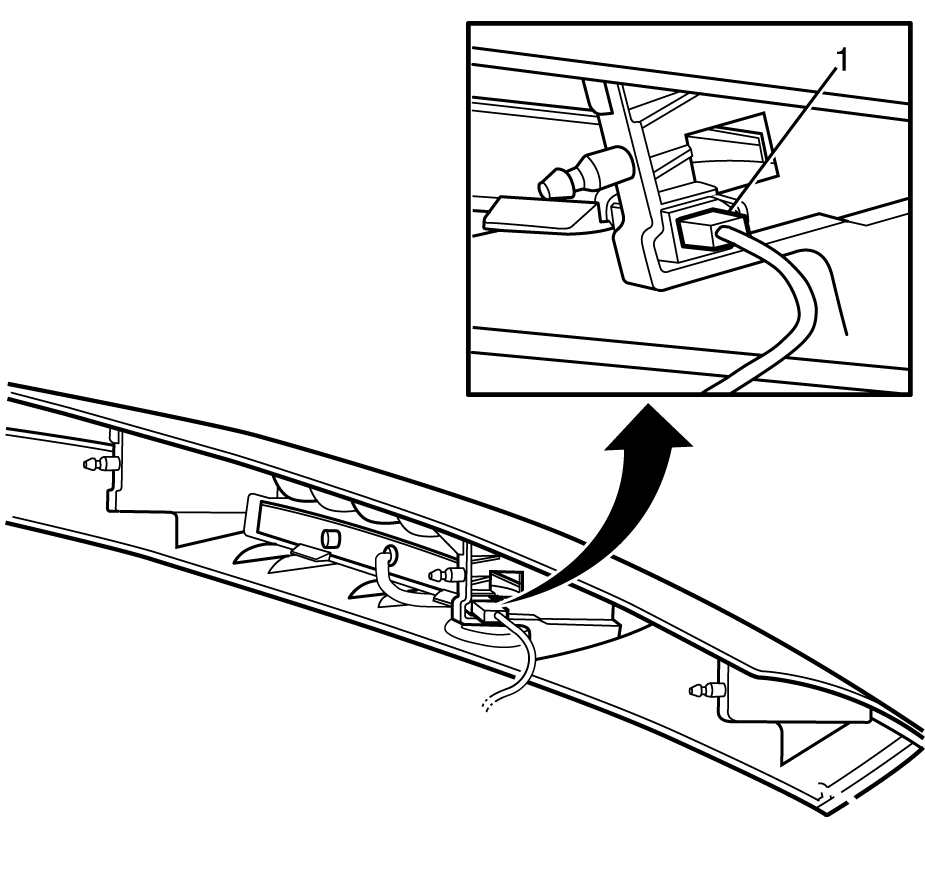
Important: Steps 5 and 6 are only applicable to vehicles fitted with a high mounted stop lamp.
Installation Procedure
- If fitted with a high mounted stop lamp, install the high mounted stop lamp to the rear header trim. Refer to High Mount Stop Lamp Replacement .
- If fitted with a high mounted stop lamp, connect the high mounted stop lamp electrical connector (1).
- If reusing the rear header trim (1), clean the inner edge of the rear header trim (1) with a suitable cleaning solution, using a lint free cloth.
- Apply NEW adhesive (2) to the rear header trim (1).
- Install the rear header trim (2) to the roof panel (3).
- Attach the body lock pillar trim to rear header trim retaining clip (1).
Important: Steps 1 and 2 are only applicable to vehicles fitted with a high mounted stop lamp.

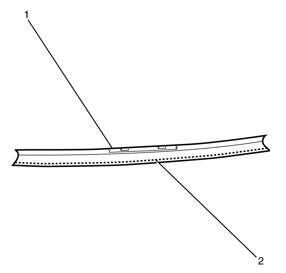
Important: The broken line (2) represents the adhesive and should be only used as a reference.

Important: Align the rear header trim retaining clips (2) to the corresponding roof panel holes (1).
Important: If a high mounted stop lamp is fitted take care not to cause damage to the wiring harness.

Important: Listen for an audible click from the rear header trim to body lock pillar retaining clip (1) to confirm correct fitment.
Important: Firmly apply pressure to the rear header trim for 30 seconds to ensure correct adhesion.
Roof Panel Rear Applique Replacement HSV Maloo
Removal Procedure
- Remove the hard tonneau cover. Refer to Customer Concern Verification Sheets .
- Remove the centre high mounted stop lamp. Refer to Customer Concern Verification Sheets .
- Remove the load compartment light. Refer to Customer Concern Verification Sheets .
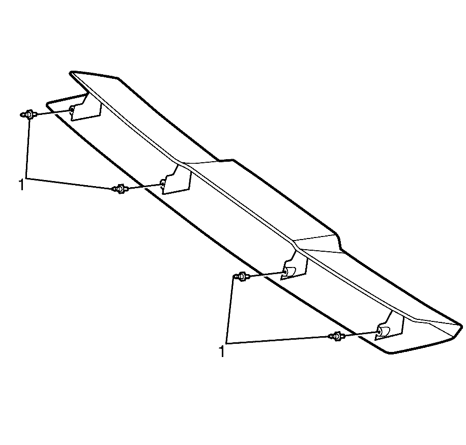
- Using a suitable plastic bladed tool, separate the adhesive tape between the leading edge of the centre header trim (1) and the roof panel (2) in the areas indicated (3).
- Remove the centre header trim panel screws (1) from the vehicle body (2) and disengage the centre header trim (3).
- Remove the centre header trim (3).
- Remove the centre header trim engagement studs (1).
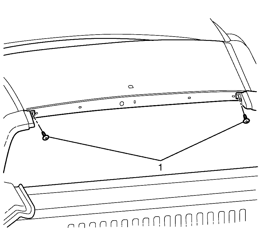
- Remove the outer header trim retention screws (1).
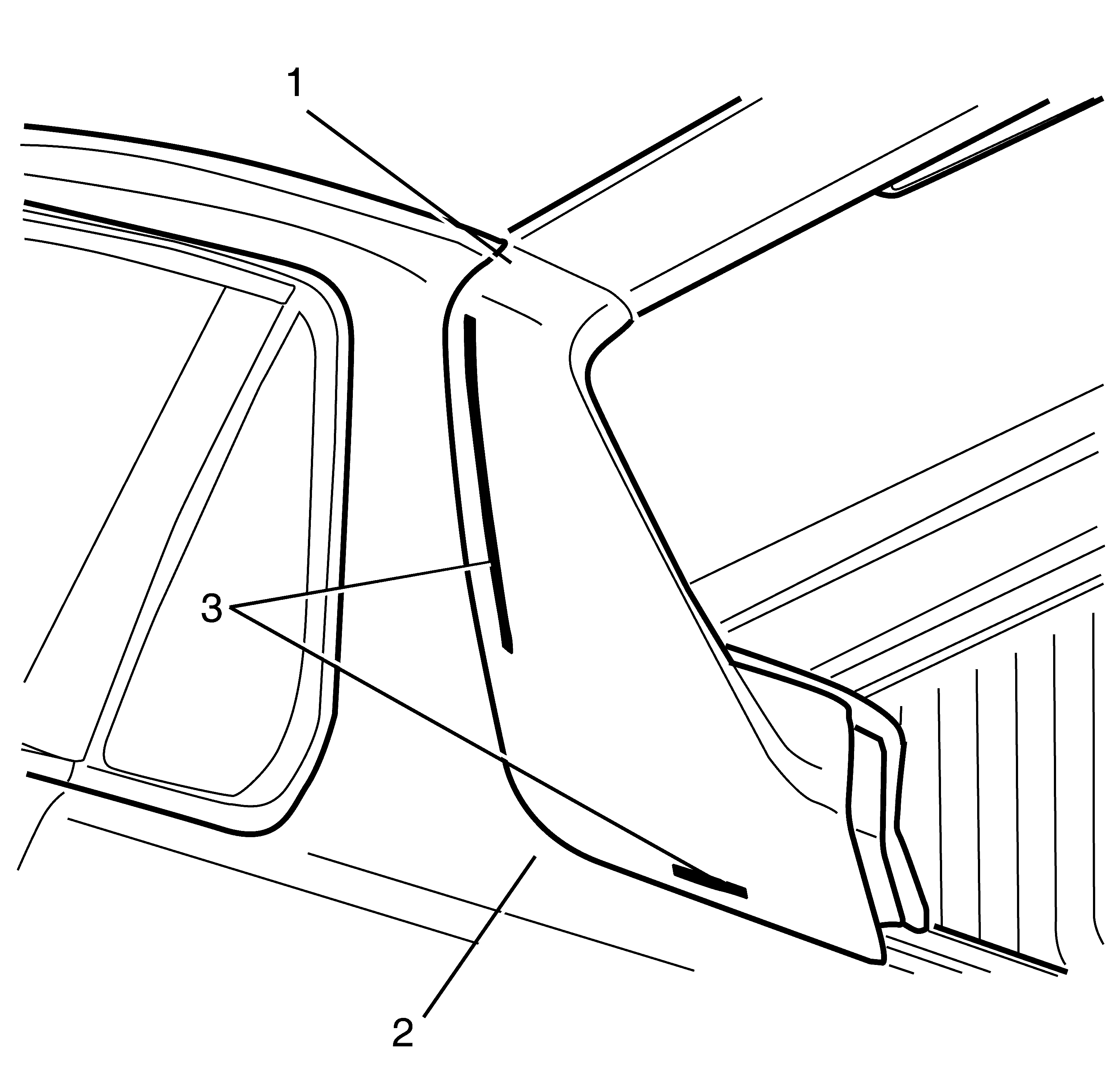
- Using a suitable plastic bladed tool, separate the adhesive between the outer header trim (1) and the body side panel (2) in the areas indicated (3).
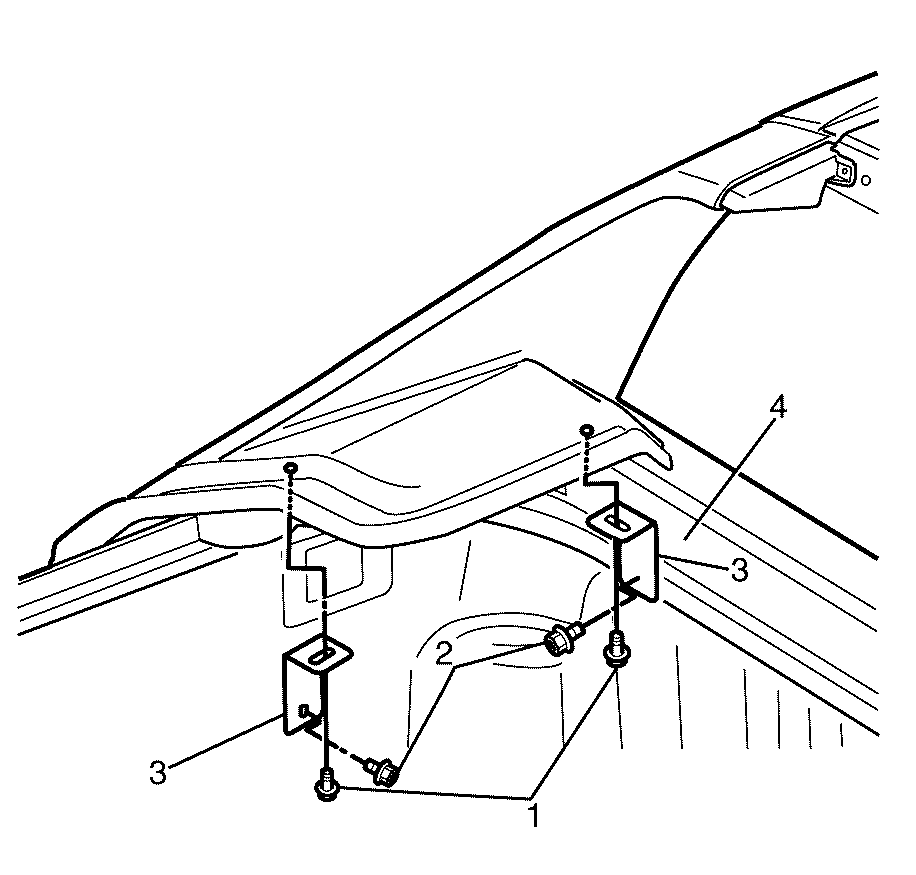
- Remove the support bracket to outer header trim fasteners (1) and support bracket to vehicle body fasteners (2).
- Remove the outer header trim support brackets (3) from the vehicle body (4).
- Disengage the outer header trim (1) from the retention bracket (2) in an upwards motion removing it from the vehicle body (3).
- Remove the sailplane rail bracket fasteners (1) and remove the sailplane rail bracket (2).
- Repeat for the opposite side of the vehicle.
Caution: Refer to Safety Glasses Caution in the Preface section.
Important: Protect the paint and body work with tape or a clean cloth. Failure to do so may result in damage to the paint work.
Important: Take care not to damage the paint work when prying the rear header trim from the roof panel.
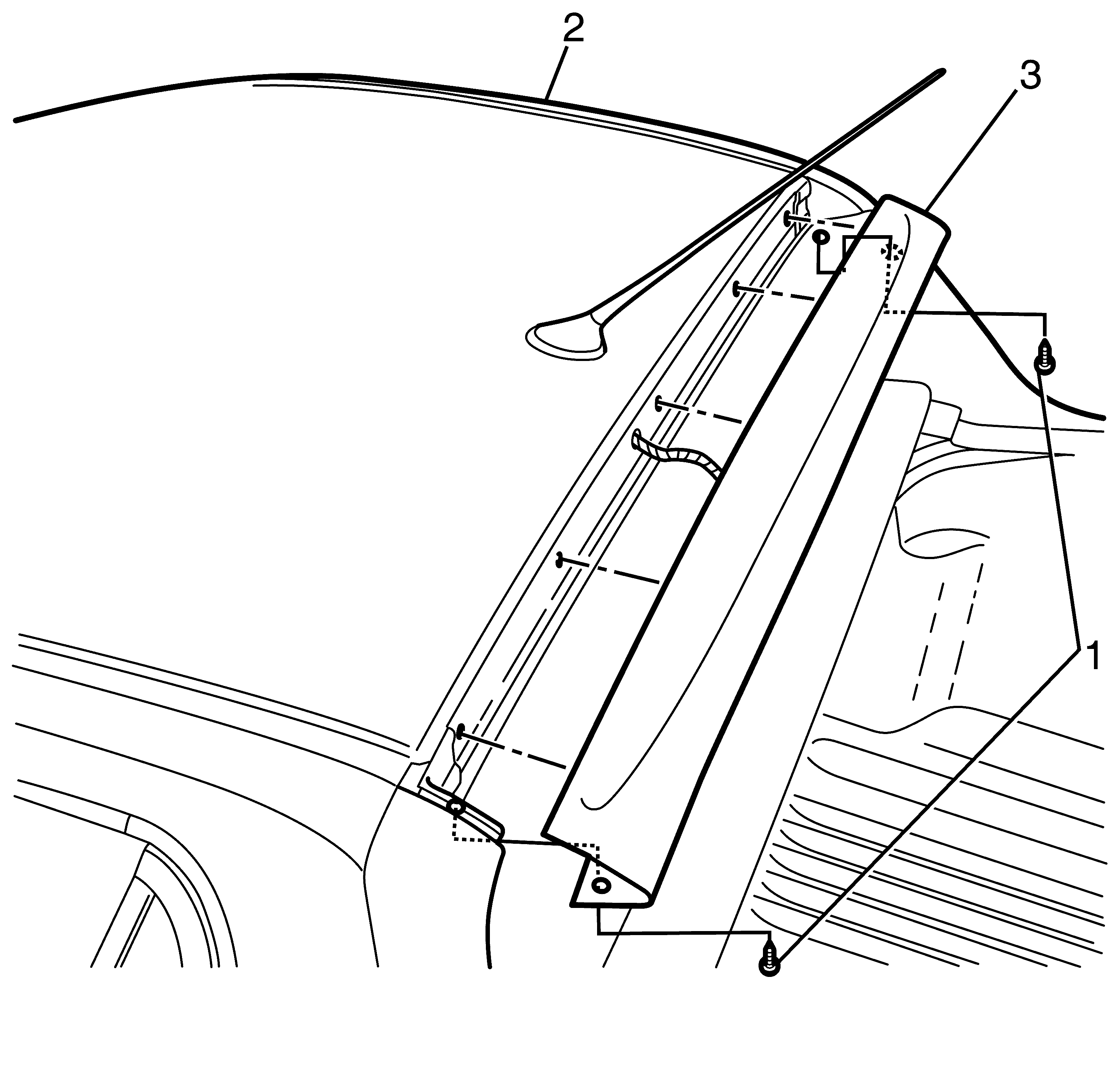
Important: Care must be taken when disengaging and removing the centre header trim so as not to cause damage to the centre high mounted stop lamp electrical wiring.
Repeat for opposite side.
Repeat for opposite side.
Repeat for opposite side.
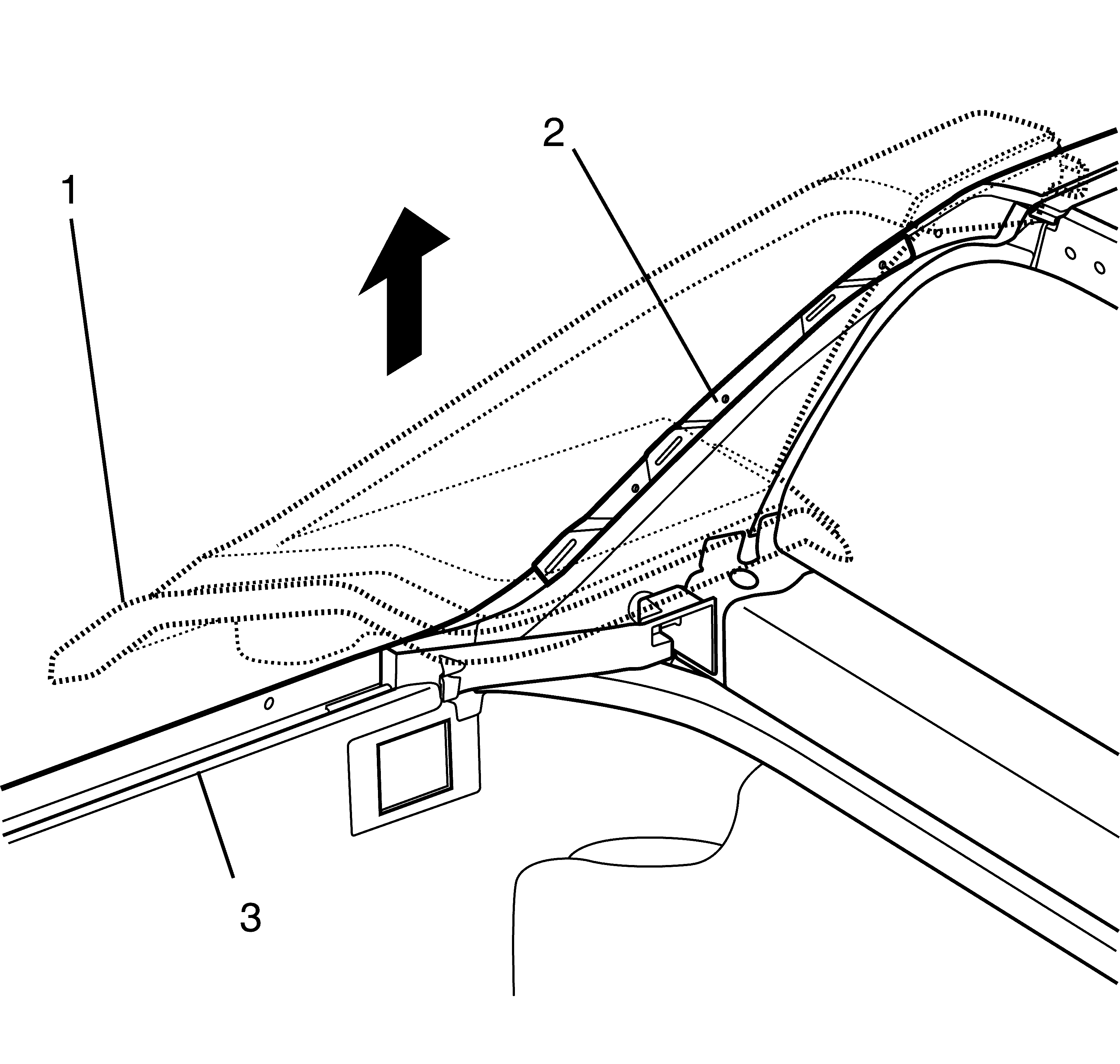
Important: Carefully remove the load compartment light electrical cabling when removing the right hand side outer header trim.
Repeat for opposite side.
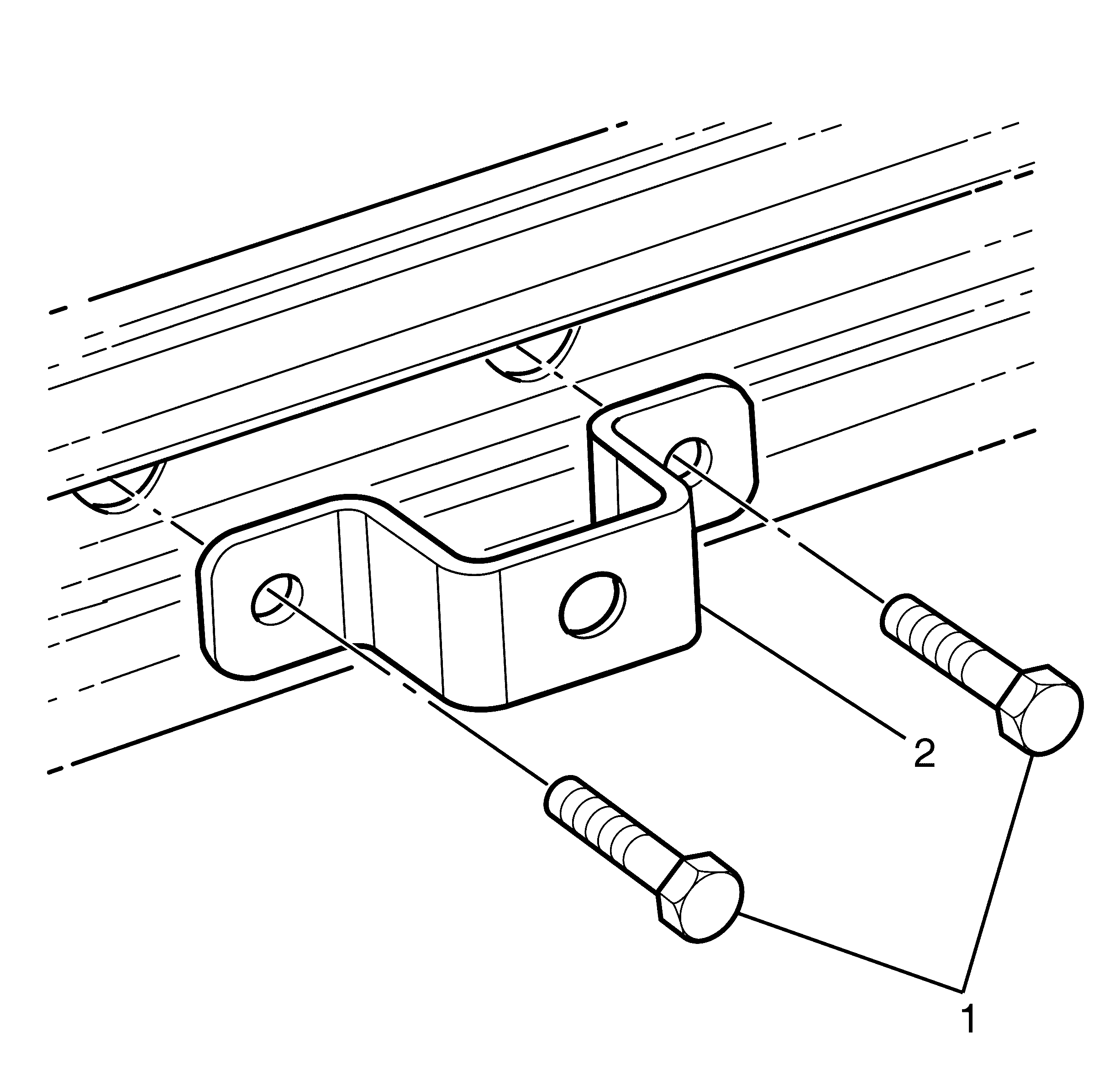
Installation Procedure
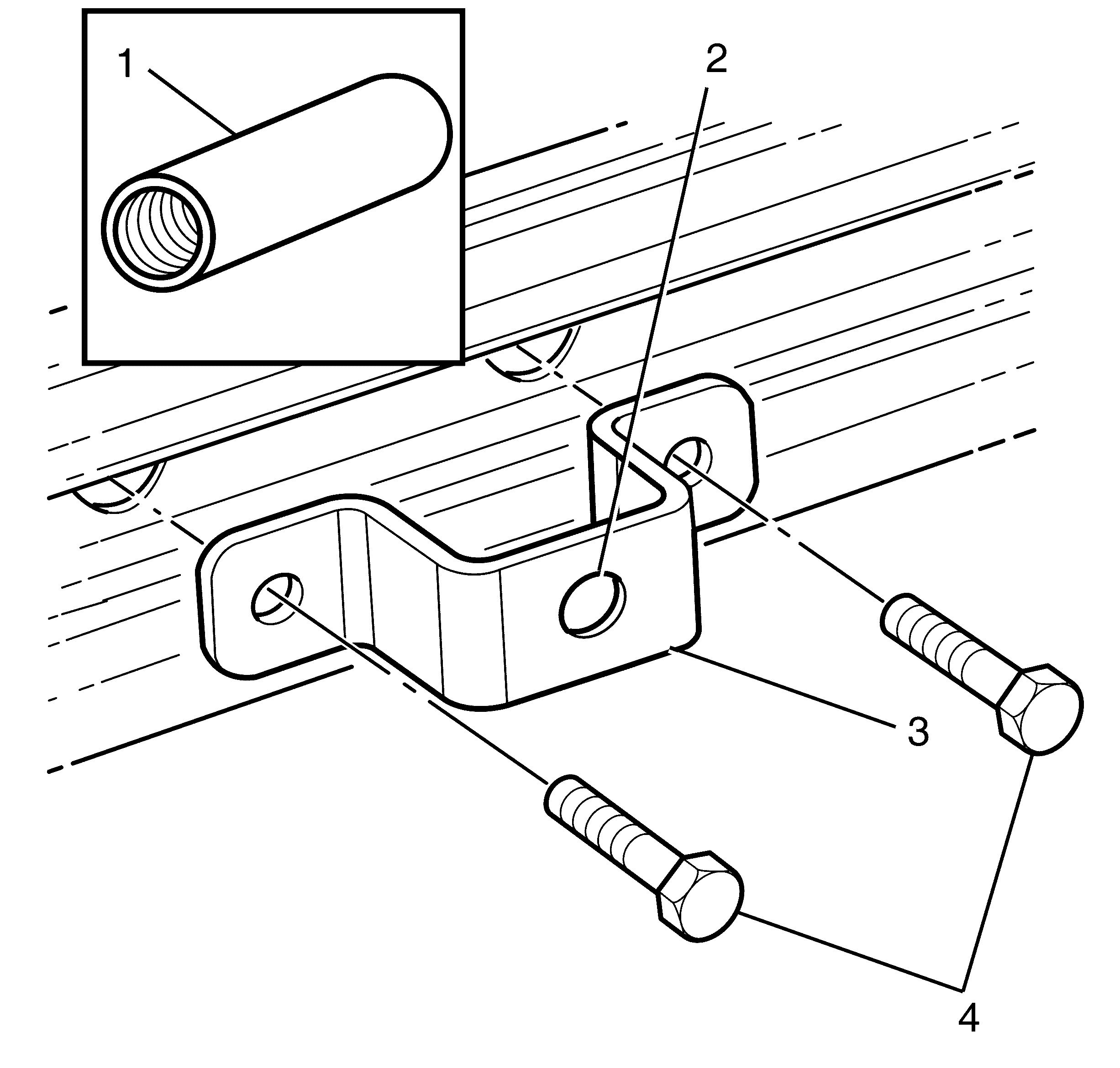
- Install a suitable threaded insert (1) into the mounting hole in the sailplane rail bracket (2).
- Install the sailplane rail bracket (3) and sailplane rail bracket fasteners (4).
- Repeat for the opposite side of the vehicle.
- Apply suitable adhesive onto the outer header trim (1) in the areas indicated (2).
- Install the outer header trim (1) in a downwards motion, engaging it onto the retention bracket (2) mounted on the vehicle body (3).
- Install the outer header trim support brackets (3) onto the vehicle body (4).
- Install the support bracket to outer header trim fasteners (1) and support bracket to vehicle body fasteners (2).
- Repeat for opposite side.
- Install the outer header trim retention screws (1).
- Apply suitable double sided tape to the indicated areas (1) on the underside of the centre header trim (2).
- Install the centre header trim engagement studs (3).
- Trim back the tape to a concealed (non visible) amount of overhang.
- Engage the centre header trim (3) onto the vehicle body (2).
- Install the centre header trim panel screws (1) into the vehicle body (2).
- Install the load compartment light. Refer to Customer Concern Verification Sheets .
- Install the centre high mounted stop lamp. Refer to Customer Concern Verification Sheets .
- Install the hard tonneau cover. Refer to Customer Concern Verification Sheets .
- Check all installed components for function and clearance against the vehicle body.
Notice: Refer to Fastener Notice in the Preface section.
Tighten
Tighten the sailplane rail bracket fasteners to
4.0 Nm (35 lb. in).
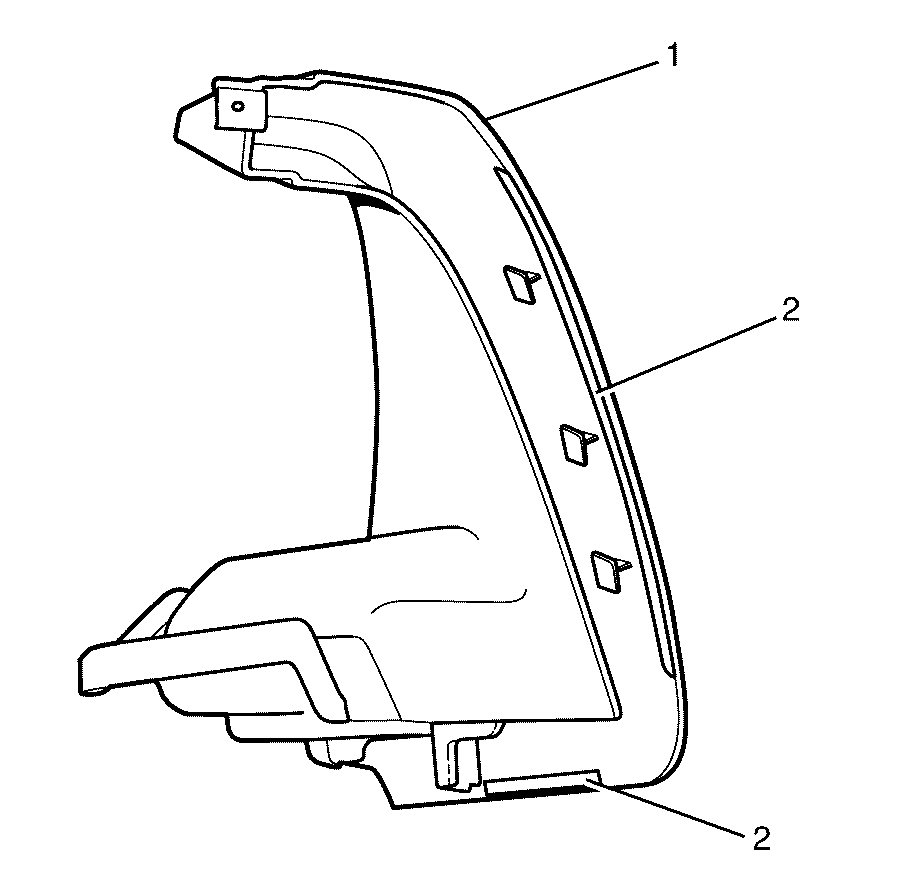
Important: All areas receiving application of an adhesive must be cleaned with a suitable alcoholic solution and a lint free cloth.
Important: Do not allow the adhesive to come in contact with the vehicle body, painted exterior surfaces or any dirt or foreign matter.
Repeat for the outer header trim to be installed on the opposite side of the vehicle.
Important: Protect the paint and body work with tape or a clean cloth. Failure to do so may result in damage to the paint work.
Important: Ensure the wiring harness for the load compartment light is carefully re-routed from the vehicle body into the right hand side outer header trim.
Important: Carefully route the load compartment light electrical cabling through the outer header trim. Care must be taken not damage the electrical cabling whilst engaging the outer header trim.
Repeat for opposite side.

Tighten
Tighten the support bracket to outer header trim
fasteners to 4.0 Nm (35 lb. in).
Tighten
Tighten the support bracket to vehicle body fasteners
to 9.0 Nm (80 lb. in).

Tighten
Tighten the outer header trim retention screws to
2.0 Nm (18 lb. in).
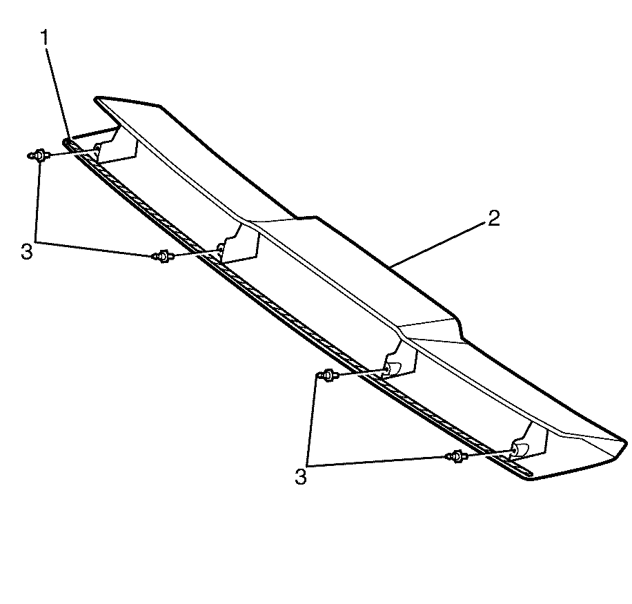
Important: Do not allow the adhesive tape to come in contact with any dirt or foreign matter.
Tighten
Tighten the centre header trim engagement studs
to 2.0 Nm (18 lb. in).

Important: Protect the paint and body work with tape or a clean cloth. Failure to do so may result in damage to the paint work.
Important: Carefully route the centre high mounted stop lamp electrical cabling through the centre header trim. Care must be taken not damage the electrical cabling whilst engaging the centre header trim.
Tighten
Tighten the centre header trim panel screws to 2.0 Nm
(18 lb. in).
