Tools Required
Customer Concern Verification Sheets
Master Cylinder to Brake Pressure Modulator Valve (BPMV) Removal Procedure
- Clean the master cylinder, especially around the brake lines and reservoir cap.
- Place a clean suitable container under the BPMV and master cylinder.
- Remove the master cylinder reservoir cap.
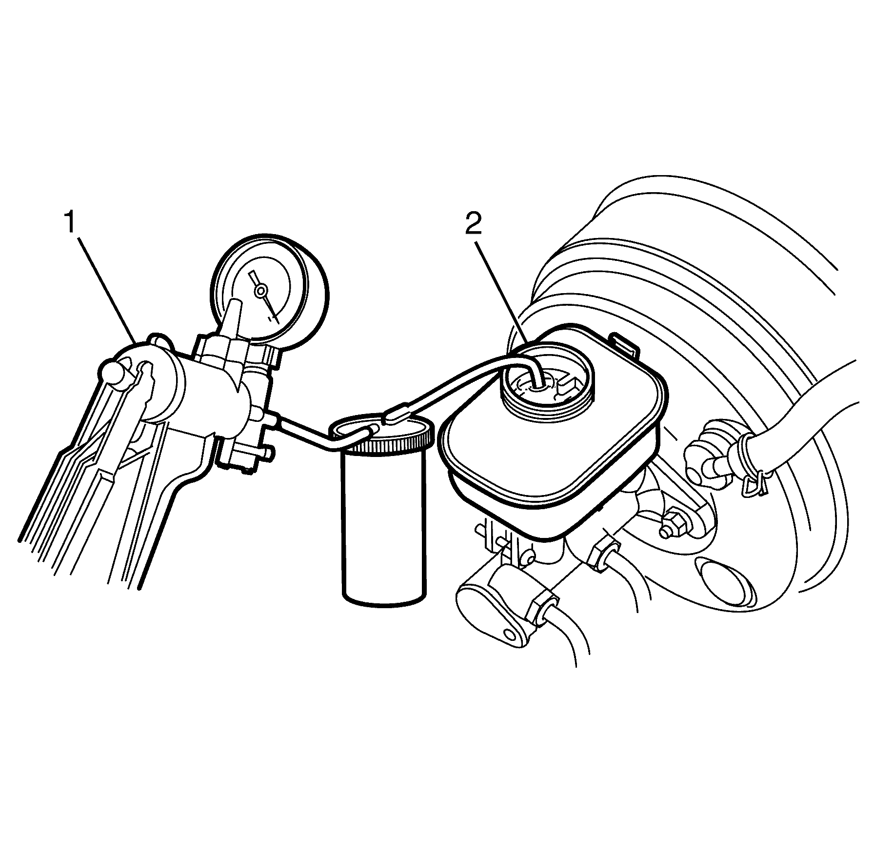
- Siphon the brake fluid out of the master cylinder reservoir (2) using the Customer Concern Verification Sheets .
- Remove the brake pipes (2) from the master cylinder (1).
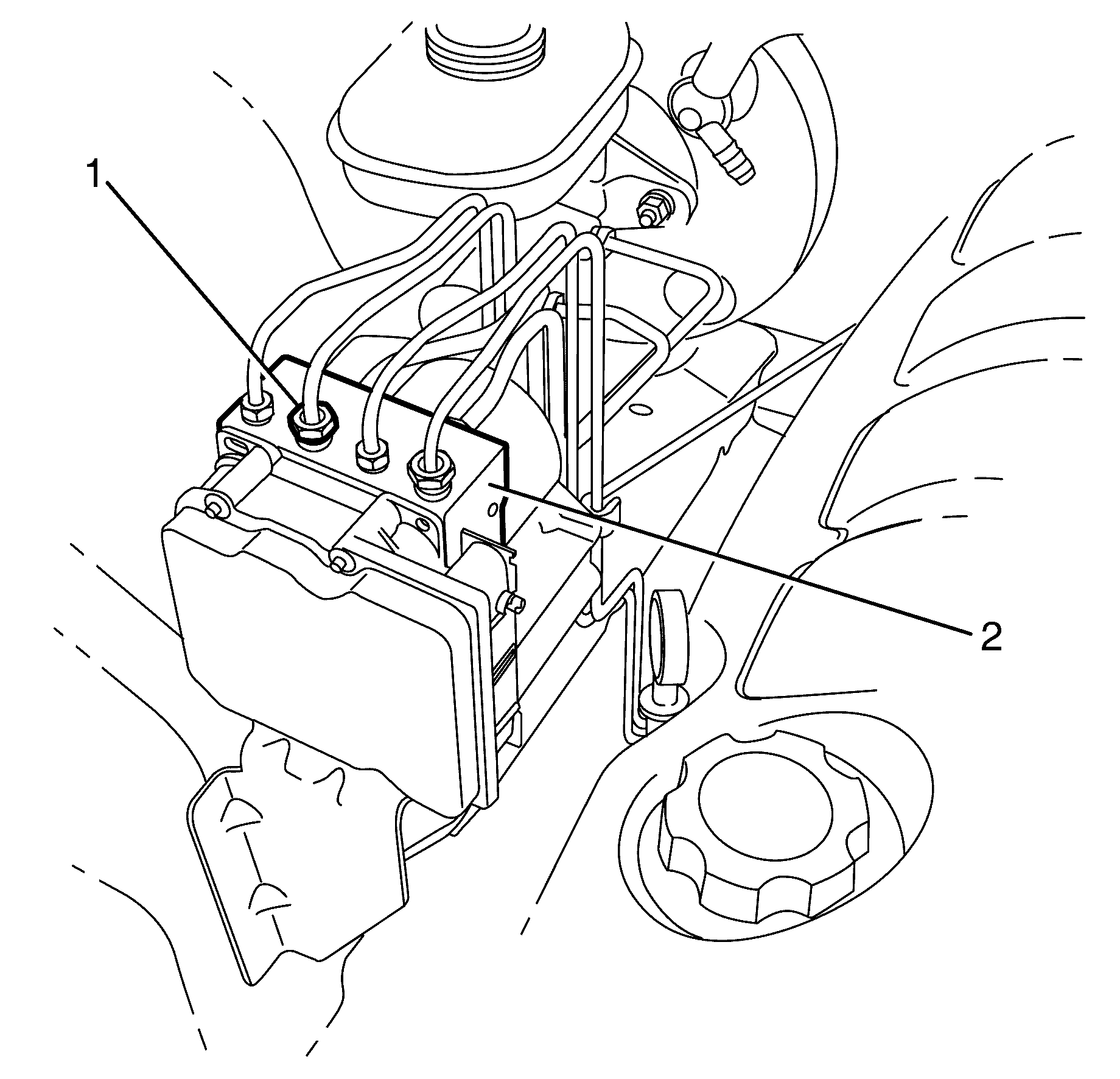
- Remove the master cylinder brake pipes (2) from the BPMV (1).
Caution: Refer to Safety Glasses Caution in the Preface section.
Caution: Refer to Brake Fluid Caution in the Preface section.
Caution: Refer to Brake Fluid Irritant Caution in the Preface section.
Notice: Refer to Adding Fluid to the Brake System Notice in the Preface section.
Notice: Refer to Brake Fluid Effects on Paint and Electrical Components Notice in the Preface section.
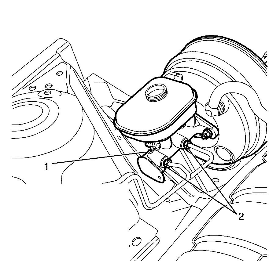
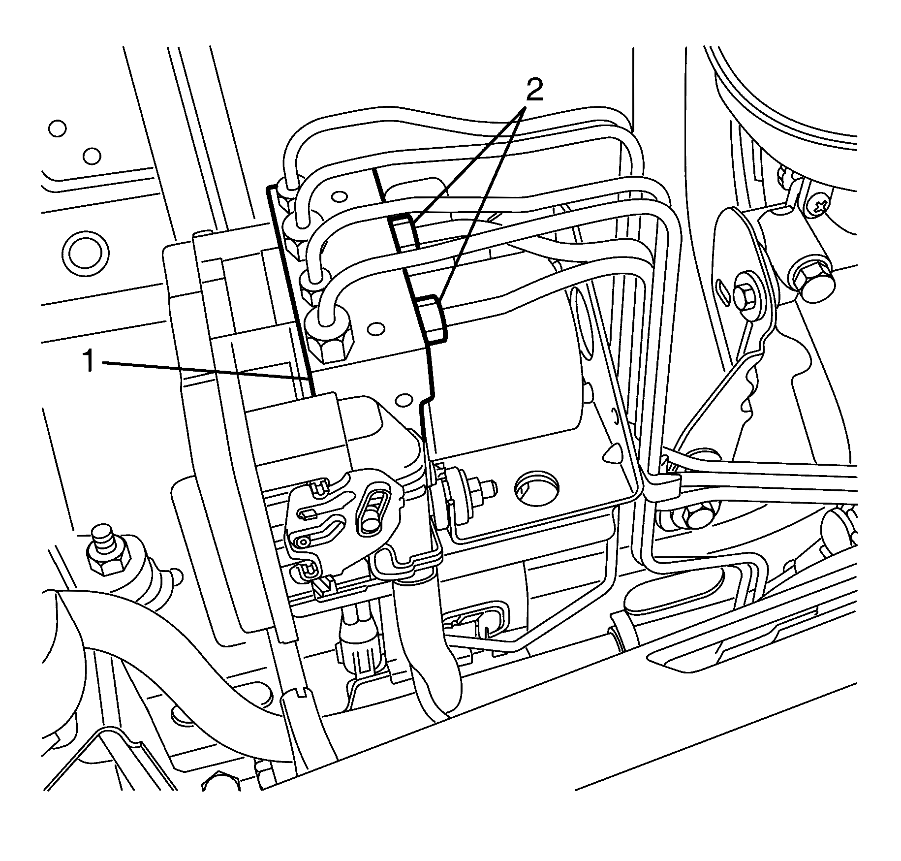
Important: Record the location of all brake pipes to the BPMV assembly for use as an aid during installation.
Master Cylinder to Brake Pressure Modulator Valve (BPMV) Installation Procedure
- Install the wheel brake pipes (2) to the BPMV (1) using the locations recorded during the removal procedure.
- Install the brake pipes (2) to the master cylinder (1).
- Bleed the hydraulic brake system. Refer to Hydraulic Brake System Bleeding(Manual) or Hydraulic Brake System Bleeding (Pressure).

Tighten
Tighten the wheel brake pipes to 15 Nm (11 lb ft).

Tighten
Tighten the pipe fittings to 15 Nm (11 lb ft).
Front Brake Pipe Removal Procedure [dash ] Right
- Clean the master cylinder, especially around the brake lines and reservoir cap.
- Place a clean suitable container under the BPMV.
- Remove the master cylinder reservoir cap.
- Siphon the brake fluid out of the master cylinder reservoir (2) using the Customer Concern Verification Sheets .
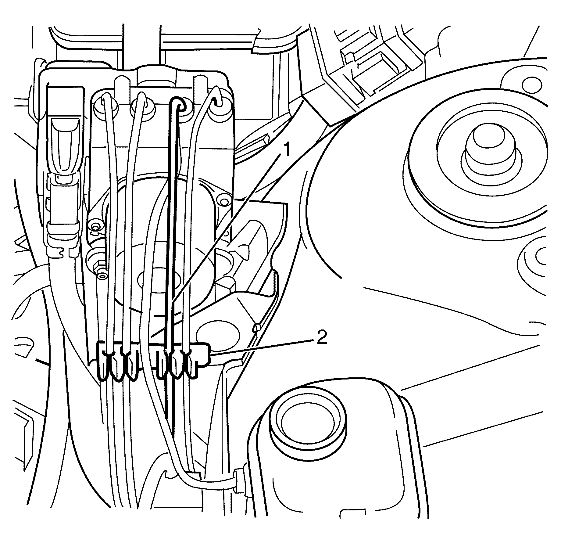
- Disconnect the brake pipe (1) from the BPMV (2).
- Plug the BPMV (2).
- Detach the brake pipe (1) from the locating clip (2).
- Raise and support the vehicle. Refer to Lifting and Jacking the Vehicle.
- Remove the right front wheel. Refer to Tire and Wheel Removal and Installation.
- Remove the right splash guard. Refer to Wheelhouse Splash Shield Replacement.
- Clean all dirt and foreign material from the brake hose and the brake pipe fittings (2 and 3).
- Disconnect the brake pipe fitting (2) from the brake hose (3).
- Plug the brake hose (3).
- Remove the brake pipe (1).
Caution: Refer to Safety Glasses Caution in the Preface section.
Caution: Refer to Vehicle Lifting Caution in the Preface section.
Caution: Refer to Brake Dust Caution in the Preface section.
Caution: Refer to Brake Fluid Caution in the Preface section.
Caution: Refer to Brake Fluid Irritant Caution in the Preface section.
Notice: Refer to Adding Fluid to the Brake System Notice in the Preface section.
Notice: Refer to Brake Fluid Effects on Paint and Electrical Components Notice in the Preface section.

Important: Install a rubber cap or plug to the BPMV (2) in order to prevent fluid loss and contamination.
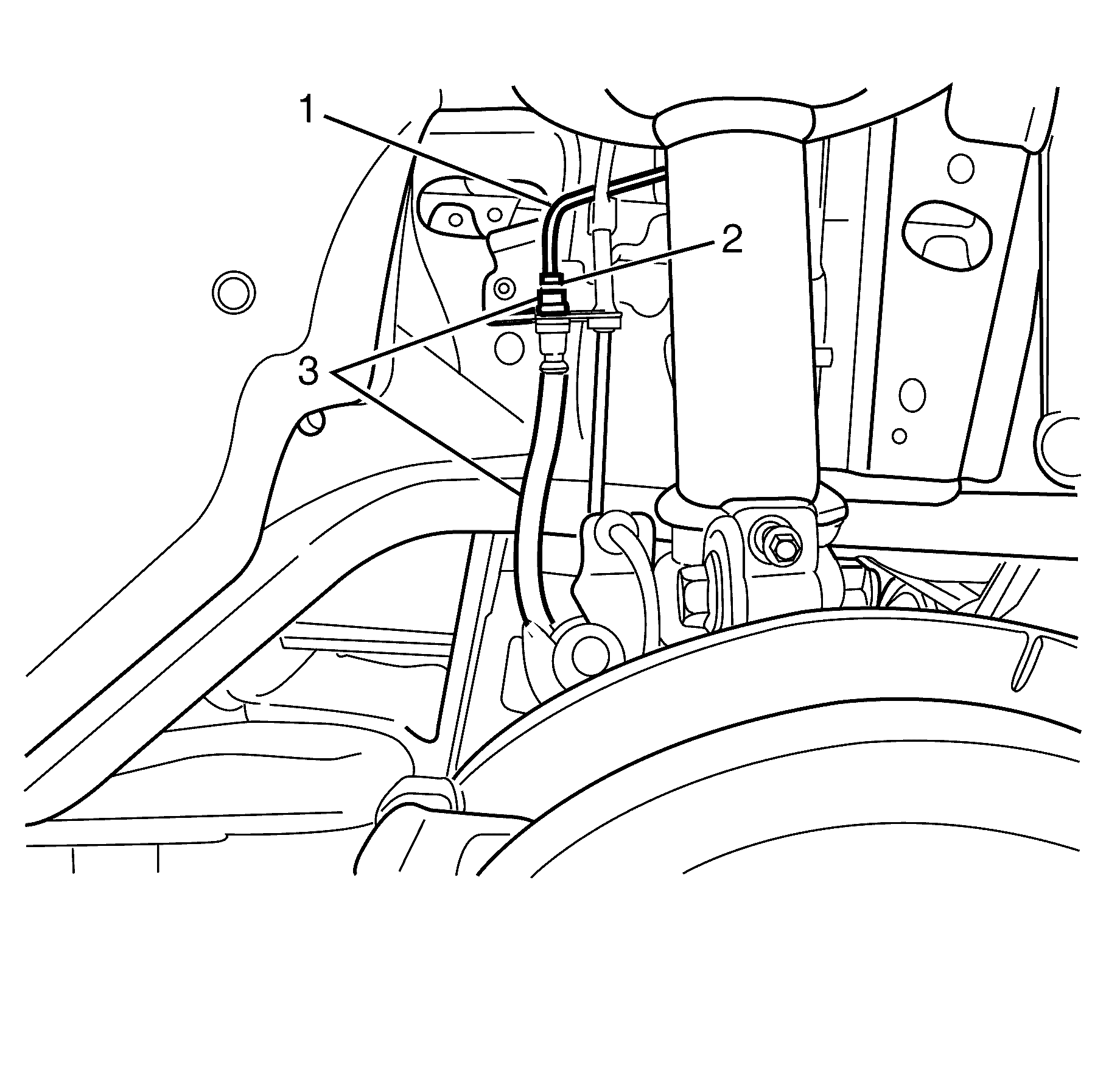
Important: Hold the brake hose (3) with a suitable tool whilst disconnecting the brake pipe fitting (2) to prevent damage to the brake pipe (1).
Important: Install a rubber cap or plug to the exposed brake hose fitting end in order to prevent brake fluid loss and contamination.
Front Brake Pipe Installation Procedure [dash ] Right
- Install the brake pipe (1) to the vehicle.
- Remove the rubber cap or plug from the brake hose (3).
- Connect the brake pipe fitting (2) to the brake hose (3).
- Lower the vehicle.
- Attach the brake pipe (1) to the locating clip (2).
- Remove the rubber cap or plug from the BPMV (2).
- Install the brake pipe (1) to the BPMV (2).
- Tighten the brake pipe fitting (2) to the brake hose (3)
- Tighten the brake pipe fitting (1) to the BPMV (2).
- Install the right splash guard. Refer to Wheelhouse Splash Shield Replacement.
- Bleed the hydraulic brake system. Refer to Hydraulic Brake System Bleeding (Manual) or Hydraulic Brake System Bleeding (Pressure).
Caution: Refer to Safety Glasses Caution in the Preface section.
Caution: Refer to Vehicle Lifting Caution in the Preface section.
Caution: Refer to Brake Dust Caution in the Preface section.
Caution: Refer to Brake Fluid Caution in the Preface section.
Caution: Refer to Brake Fluid Irritant Caution in the Preface section.
Notice: Refer to Adding Fluid to the Brake System Notice in the Preface section.
Notice: Refer to Brake Fluid Effects on Paint and Electrical Components Notice in the Preface section.

Do not fully tighten at this stage.


Do not fully tighten at this stage.
Notice: Refer to Fastener Notice in the Preface section.

Important: Hold the brake hose (3) with a suitable tool whilst connecting the brake pipe fitting (2) to prevent damage to the brake pipe (1).
Tighten
Tighten the brake pipe fitting to 15 Nm (11 lb ft).

Tighten
Tighten the brake pipe fitting to 15 Nm (11 lb ft).
Front Brake Pipe Removal Procedure [dash ] Left
- Clean the master cylinder, brake lines and reservoir cap.
- Place a clean suitable container under the Brake Pressure Modulator Valve (BPMV).
- Remove the master cylinder reservoir cap.
- Siphon the brake fluid out of the master cylinder reservoir (2) using the Customer Concern Verification Sheets .
- Disconnect the brake pipe (1) from the BPMV (2).
- Plug the BPMV (2).
- Raise and support the vehicle. Refer to Lifting and Jacking the Vehicle.
- Remove the engine. Refer to Engine Replacement - 3.6L or Customer Concern Verification Sheets
- Remove the heat shields in the engine bay.
- Remove the sound proofing trim from the bulkhead.
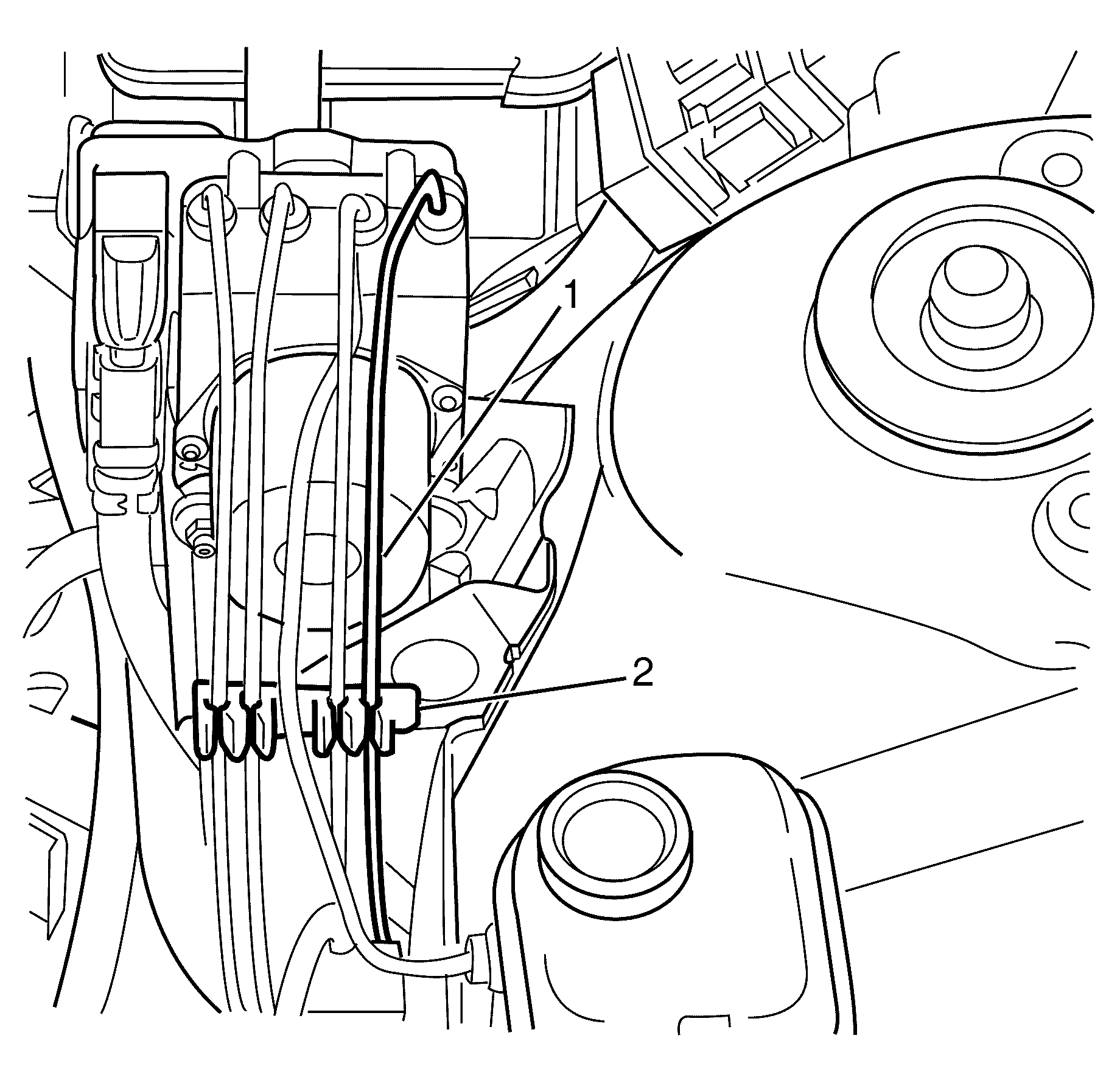
- Detach the brake pipe (1) from the locating clip (2).
- Detach the brake pipe (1) from the locating clip (2).
- Detach the brake pipe (1) from the locating clips (2).
- Clean all dirt and foreign material from the brake hose and the brake pipe fittings (1 and 3).
- Disconnect the brake pipe fitting (3) from the brake hose (1).
- Plug the brake hose (1).
- Remove the left splash guard. Refer to Wheelhouse Splash Shield Replacement.
- Remove the brake pipe (2) from the vehicle.
Caution: Refer to Safety Glasses Caution in the Preface section.
Caution: Refer to Vehicle Lifting Caution in the Preface section.
Caution: Refer to Brake Dust Caution in the Preface section.
Caution: Refer to Brake Fluid Caution in the Preface section.
Caution: Refer to Brake Fluid Irritant Caution in the Preface section.
Notice: Refer to Adding Fluid to the Brake System Notice in the Preface section.
Notice: Refer to Brake Fluid Effects on Paint and Electrical Components Notice in the Preface section.

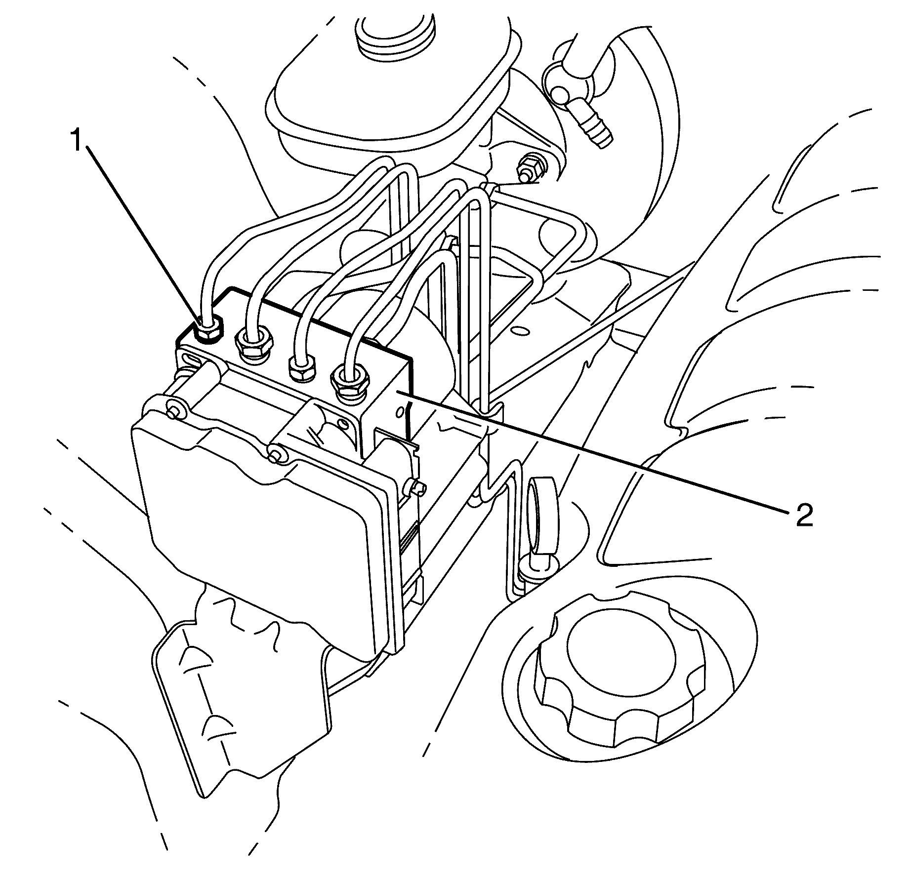
Important: Install a rubber cap or plug to the BPMV (2) in order to prevent fluid loss and contamination.
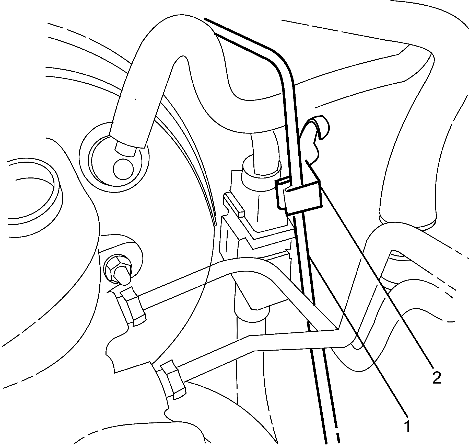
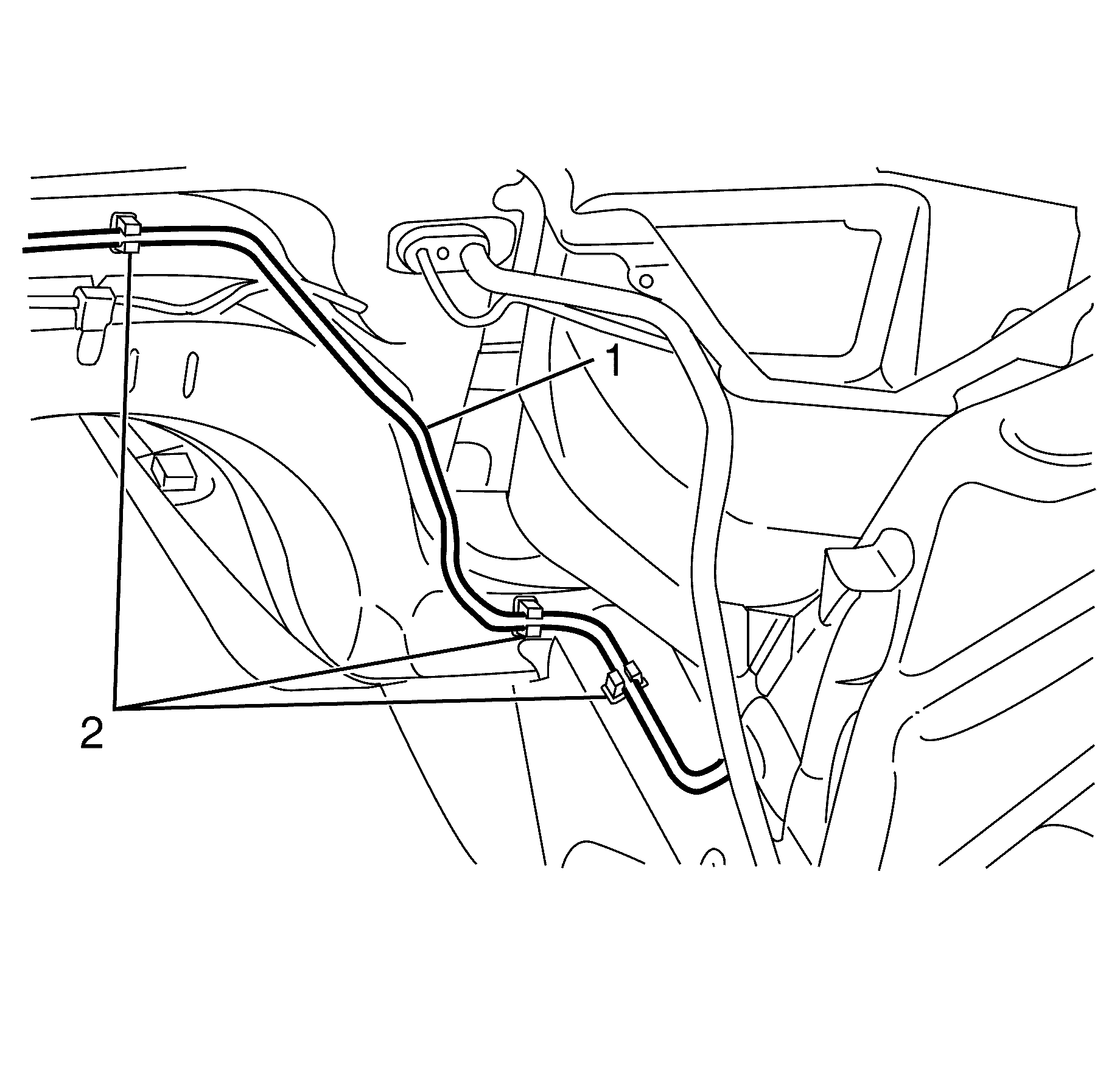
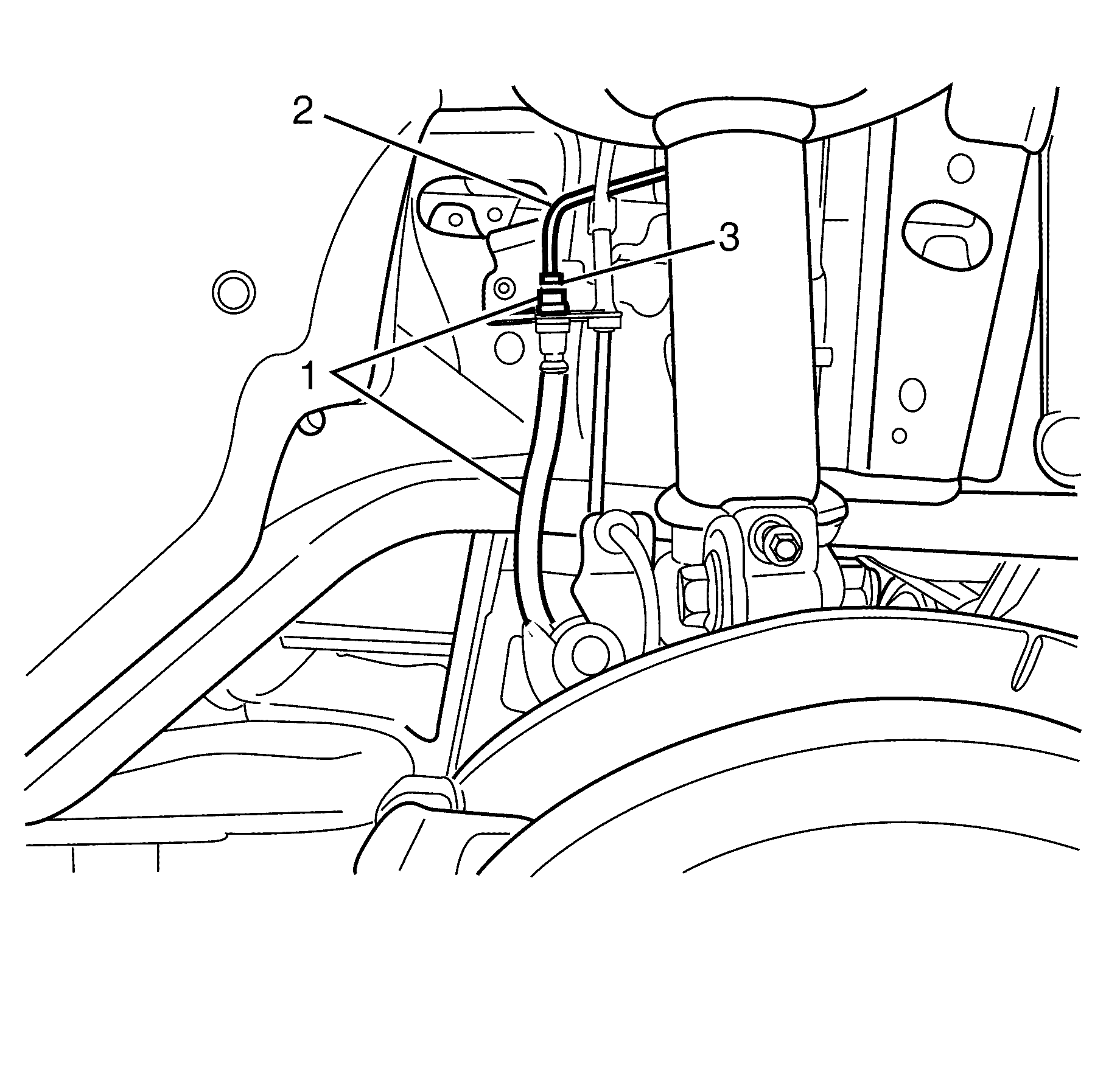
Important: Hold the brake hose (1) with a suitable tool whilst disconnecting the brake pipe fitting (3) to prevent damage to the brake pipe (2).
Important: Install a rubber cap or plug to the exposed brake hose (1) in order to prevent brake fluid loss and contamination.
Front Brake Pipe Installation Procedure [dash ] Left
- Install the brake pipe (2) to the vehicle.
- Remove the rubber cap or plug from the brake hose (1).
- Connect the brake pipe (2) to the brake hose (1).
- Lower the vehicle.
- Attach the brake pipe (1) to the locating clip (2).
- Attach the brake pipe (1) to the locating clip (2).
- Attach the brake pipe (1) to the locating clips (2).
- Remove the rubber cap or plug from the BPMV (2).
- Install the brake pipe (1) to the BPMV (2).
- Tighten the brake pipe fitting (3) to the brake hose (1)
- Tighten the brake pipe fitting (1) to the BPMV (2)
- Install the sound proofing trim to the bulkhead.
- Install the heat shields to the engine bay.
- Install the engine. Refer to Engine Replacement - 3.6L or Customer Concern Verification Sheets .
- Install the left splash guard. Refer to Wheelhouse Splash Shield Replacement.
- Bleed the hydraulic brake system. Refer to Hydraulic Brake System Bleeding (Manual) or Hydraulic Brake System Bleeding (Pressure).
Caution: Refer to Safety Glasses Caution in the Preface section.
Caution: Refer to Vehicle Lifting Caution in the Preface section.
Caution: Refer to Brake Dust Caution in the Preface section.
Caution: Refer to Brake Fluid Caution in the Preface section.
Caution: Refer to Brake Fluid Irritant Caution in the Preface section.
Notice: Refer to Adding Fluid to the Brake System Notice in the Preface section.
Notice: Refer to Brake Fluid Effects on Paint and Electrical Components Notice in the Preface section.


Do not fully tighten at this stage.
Notice: Refer to Fastener Notice in the Preface section.

Important: Hold the brake hose (1) with a suitable tool whilst connecting the brake pipe fitting (3) to prevent damage to the brake pipe (2).
Tighten
Tighten the brake pipe fitting to 15 Nm (11 lb ft).

Tighten
Tighten the brake pipe fitting to 15 Nm (11 lb ft).
Intermediate Brake Pipe Removal Procedure
- Clean the master cylinder, brake lines and reservoir cap.
- Place a clean suitable container under the Brake Pressure Modulator Valve (BPMV).
- Remove the master cylinder reservoir cap.
- Siphon the brake fluid out of the master cylinder reservoir (2) using the Customer Concern Verification Sheets .
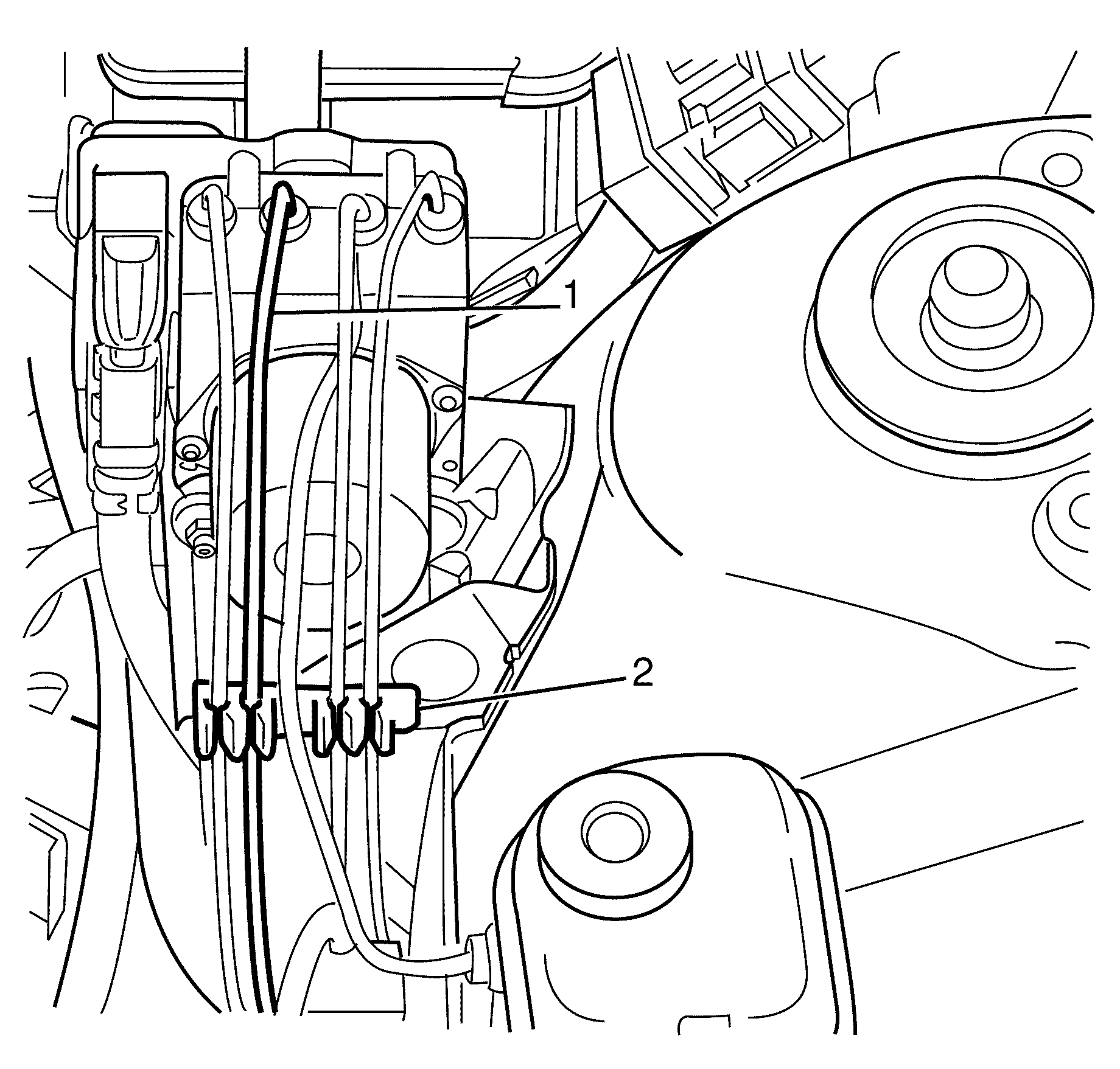
- Disconnect the brake pipe (1) from the BPMV (2).
- Plug the BPMV (2).
- Detach the brake pipe (1) to the locating clip (2).
- Raise and support the vehicle. Refer to Lifting and Jacking the Vehicle.
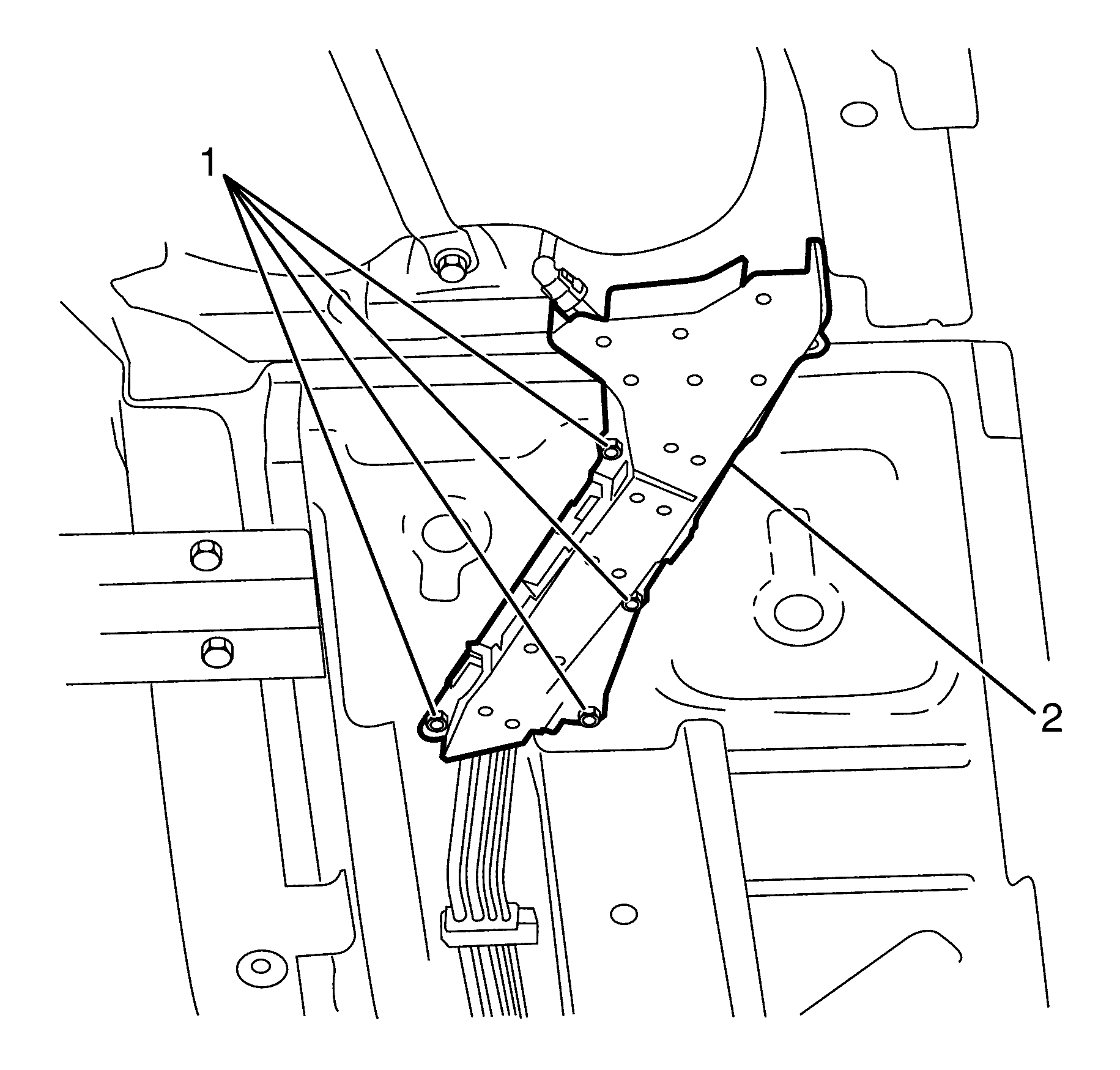
- Remove the brake and fuel pipe splash shield to chassis retaining nuts (1).
- Remove the brake and fuel pipe splash shield (2).
- Remove the front heat shield. Refer to Exhaust Front Heat Shield Replacement.
- Remove the engine. Refer to Engine Replacement - 3.6L or Customer Concern Verification Sheets
- Remove the brake and fuel pipe heat shield to bulkhead retaining rivets (2).
- Remove the brake and fuel pipe heat shield to bulkhead retaining bolt (4).
- Detach the brake and fuel pipe heat shield clips (1).
- Remove the brake and fuel pipe protector shield (2).
- Remove the rear subframe. Refer to Rear Frame Replacement.
- Disconnect the intermediate brake pipe (3) from the brake pipe union (1).
- Plug the brake pipe union (1).
- Remove the brake and fuel pipe retaining bracket to chassis retaining rivets (3).
- Remove the brake and fuel pipe retaining brackets (2).
- Remove the brake pipes (4) from the brake and fuel pipe retaining bracket rubber insulators (1).
- Open the brake and fuel pipe retaining brackets (2).
- Remove the brake pipe (1) from the brake and fuel pipe retaining bracket rubber insulators (3).
Caution: Refer to Safety Glasses Caution in the Preface section.
Caution: Refer to Vehicle Lifting Caution in the Preface section.
Caution: Refer to Brake Dust Caution in the Preface section.
Caution: Refer to Brake Fluid Caution in the Preface section.
Caution: Refer to Brake Fluid Irritant Caution in the Preface section.
Notice: Refer to Adding Fluid to the Brake System Notice in the Preface section.
Notice: Refer to Brake Fluid Effects on Paint and Electrical Components Notice in the Preface section.

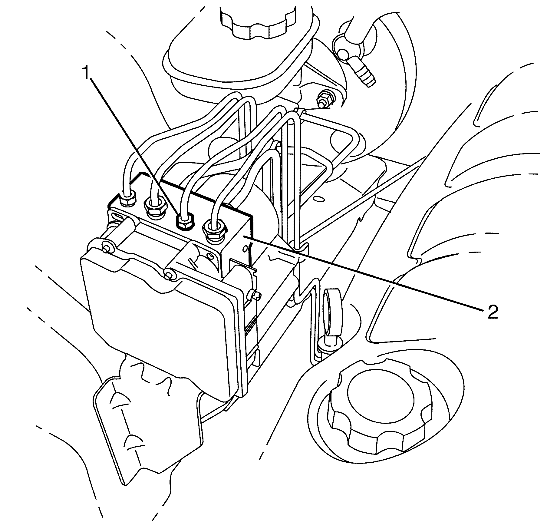
Important: Install a rubber cap or plug to the BPMV (2) in order to prevent fluid loss and contamination.
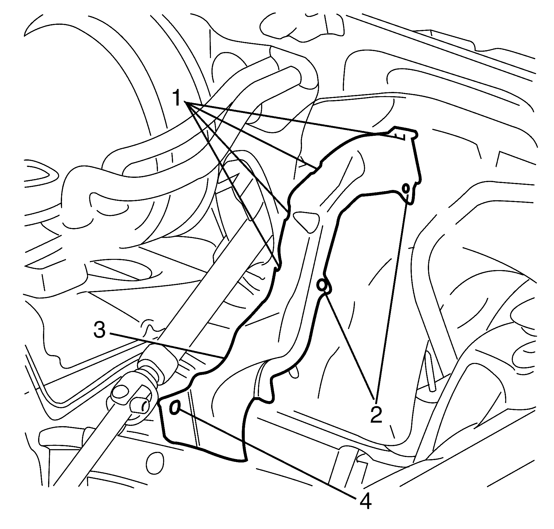
Important: The brake and fuel pipe protector shield (3) is retained by rivets (2). These rivets (2) must be drilled out during removal and replaced as per the installation procedure.
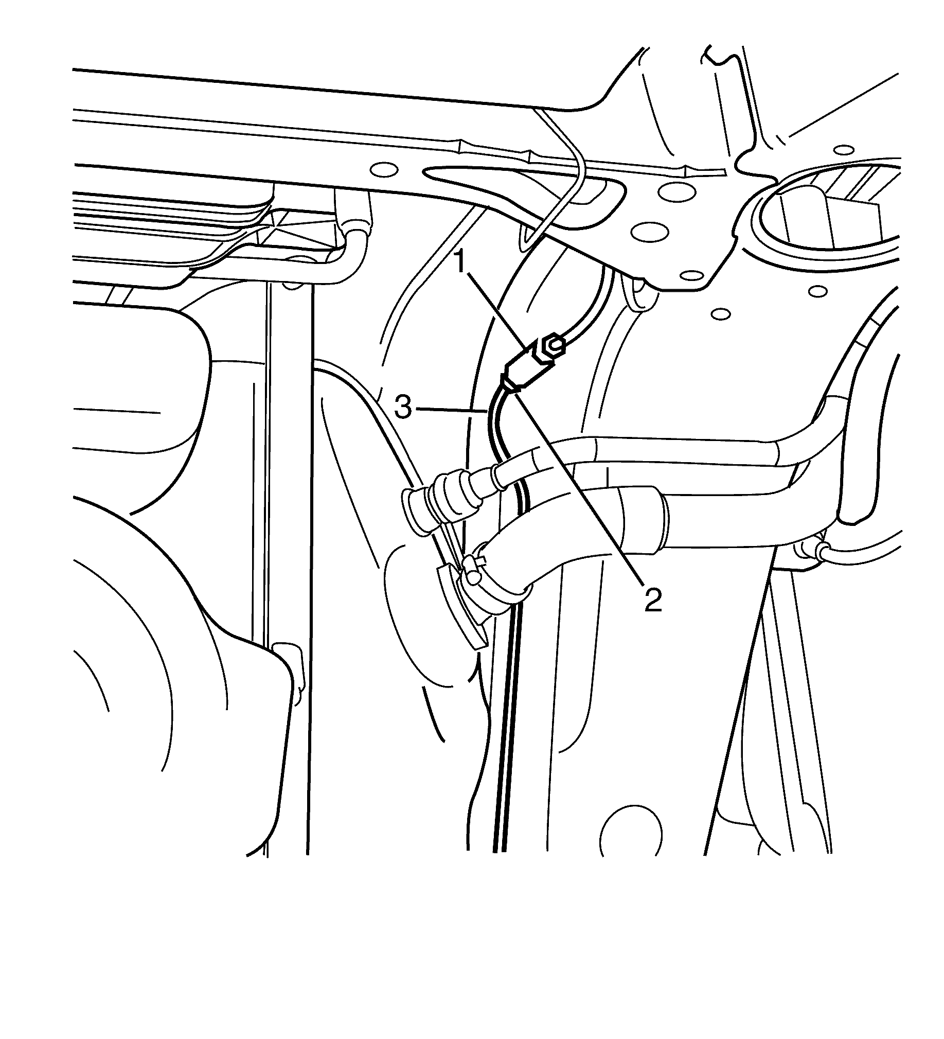
Important: Hold the brake pipe union (1) with a suitable tool whilst disconnecting the brake pipe fitting (2) to prevent damage to the intermediate brake pipe (3).
Important: Install a rubber cap or plug to the brake pipe union (1) in order to prevent brake fluid loss and/or contamination.
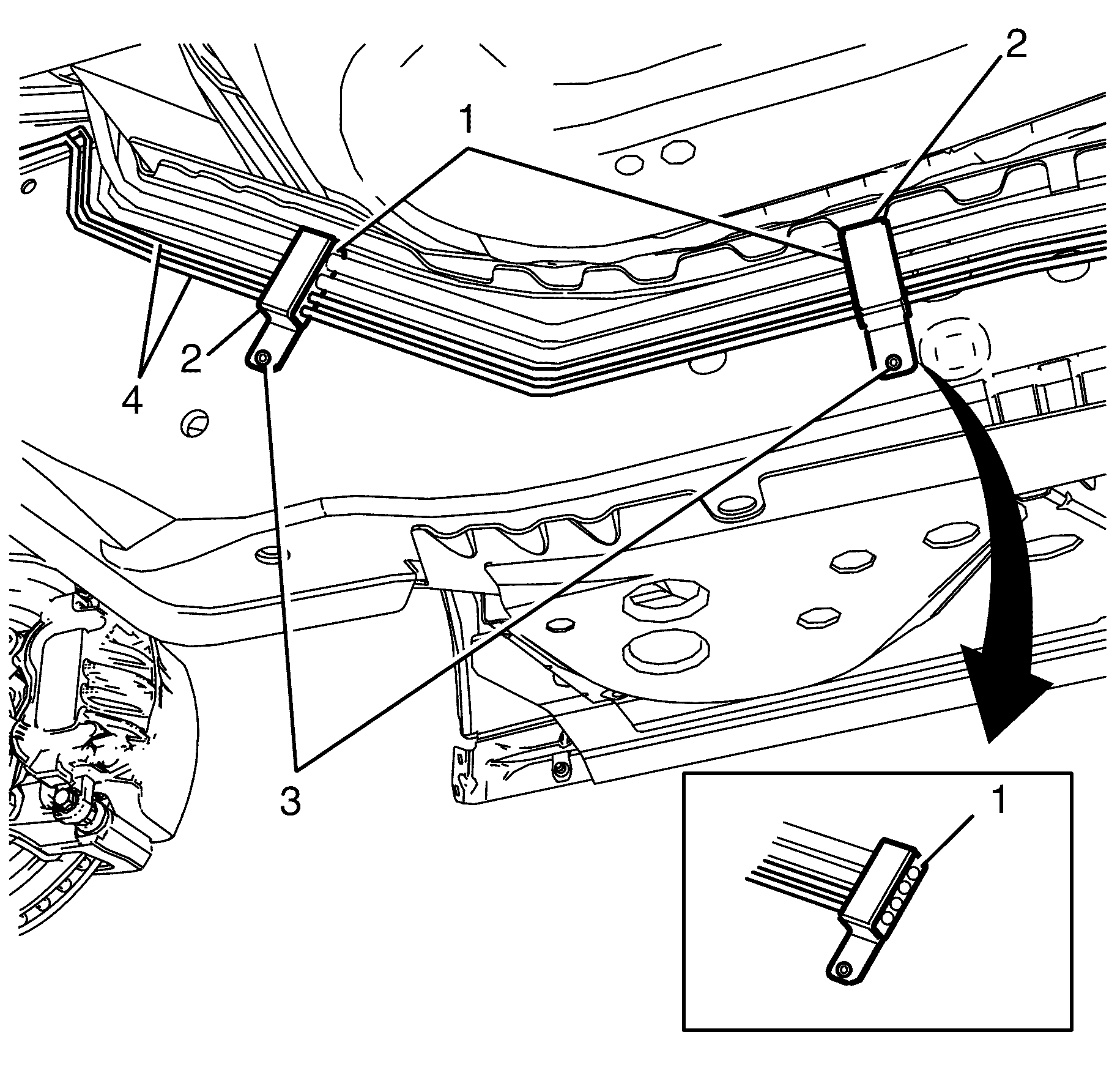
Important: The brake and fuel pipe retaining brackets (2) are retained by rivets (3). These rivets (3) must be drilled out during removal and replaced as per the installation procedure.
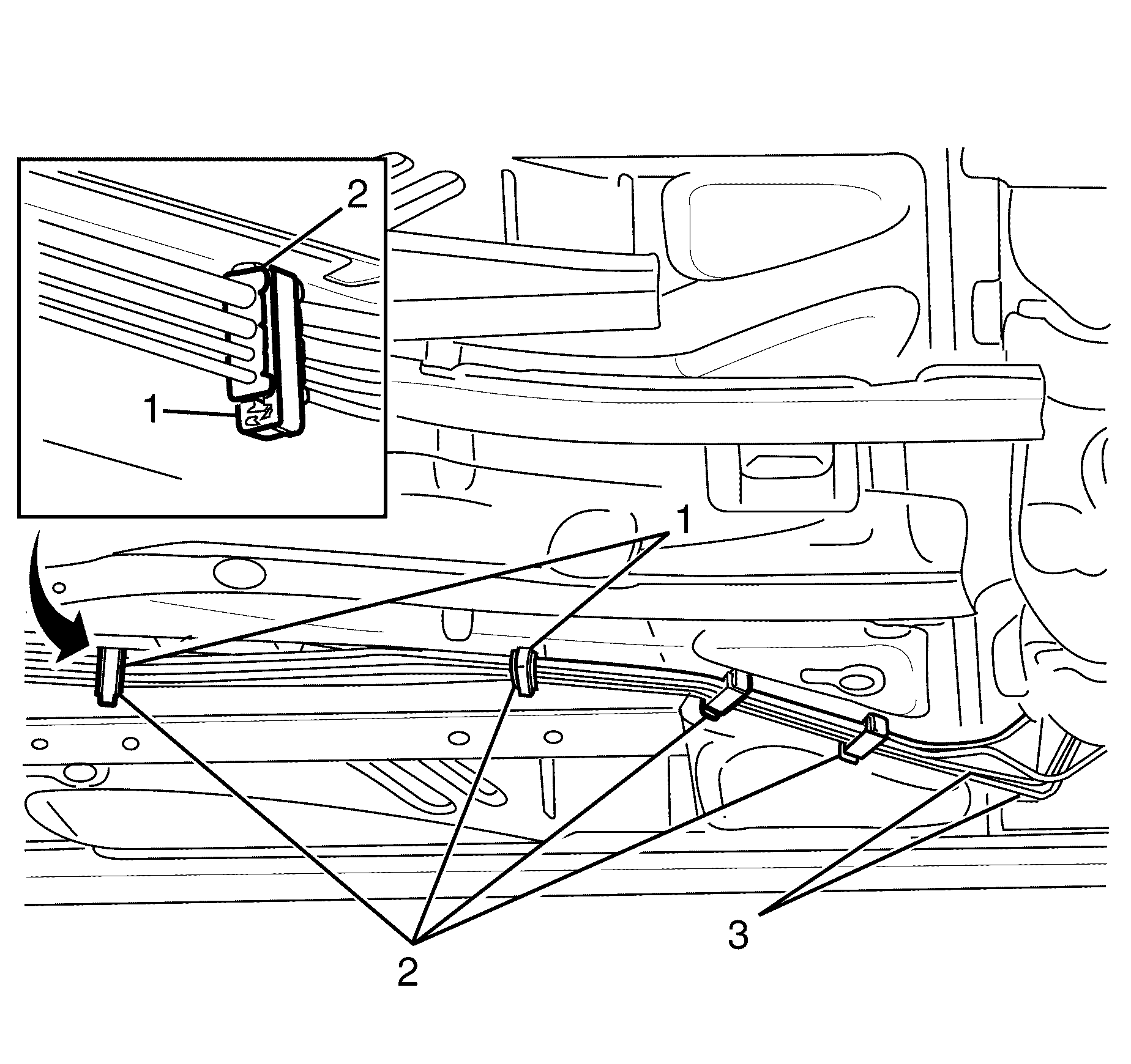
Important: Use a suitable tool to open the brake and fuel pipe retaining brackets (2) by detaching the brake and fuel pipe retaining bracket (2) clip.
Intermediate Brake Pipe Installation Procedure
- Install the brake pipes (3) to the brake and fuel pipe retaining bracket rubber insulators (2).
- Close the brake and fuel pipe retaining brackets (1).
- Install the brake pipes (4) to the two brake and fuel pipe retaining bracket rubber insulators (1).
- Install the two brake and fuel pipe retaining brackets (2).
- Install the NEW brake and fuel pipe retaining bracket to chassis retaining rivets (3).
- Remove the rubber cap or plug from the brake pipe union.
- Connect the brake pipe (1) to the brake pipe union (2).
- Attach the brake pipe (1) to the locating clip (2).
- Remove the rubber cap or plug from the BPMV (2).
- Install the brake pipe (1) to the BPMV (2).
- Tighten the brake pipe (1) to the brake pipe union (2).
- Tighten the brake pipe (1) to the BPMV (2).
- Install the rear subframe. Refer to Rear Frame Replacement.
- Install the brake and fuel pipe splash shield (2) to the underbody.
- Install the brake and fuel pipe splash shield to chassis retaining nuts (1).
- Lower the vehicle.
- Install the brake and fuel pipe heat shield (3).
- Attach the brake and fuel pipe heat shield clips (1).
- Install NEW brake and fuel pipe protector shield to bulkhead retaining rivets (2).
- Install the brake and fuel pipe protector shield to bulkhead retaining bolt (4).
- Install the engine. Refer to Engine Replacement - 3.6L or Customer Concern Verification Sheets .
- Install the front heat shield. Refer to Exhaust Front Heat Shield Replacement.
- Bleed the hydraulic brake system. Refer to Hydraulic Brake System Bleeding(Manual) or Hydraulic Brake System Bleeding(Pressure).
Caution: Refer to Safety Glasses Caution in the Preface section.
Caution: Refer to Vehicle Lifting Caution in the Preface section.
Caution: Refer to Brake Dust Caution in the Preface section.
Caution: Refer to Brake Fluid Caution in the Preface section.
Caution: Refer to Brake Fluid Irritant Caution in the Preface section.
Notice: Refer to Adding Fluid to the Brake System Notice in the Preface section.
Notice: Refer to Brake Fluid Effects on Paint and Electrical Components Notice in the Preface section.


Important: Hold the brake pipe union (1) with a spanner whilst connecting the brake pipe fitting (2) to prevent damage to the brake pipe (3).


Notice: Refer to Fastener Notice in the Preface section.

Important: Hold the brake pipe union (1) with a suitable tool whilst connecting the brake pipe fitting (2) to prevent damage to the brake pipe (3).
Tighten
Tighten the brake pipe fitting to 15 N·m
(11 lb ft).

Tighten
Tighten the brake pipe fitting to 15 N·m
(11 lb ft).

Tighten
Tighten the nuts to 5 N·m (43 lb in).

Rear Brake Pipe Removal Procedure [dash ] Right
- Clean the master cylinder, brake lines and reservoir cap.
- Place a clean suitable container under the BPMV and master cylinder.
- Remove the master cylinder reservoir cap.
- Siphon the brake fluid out of the master cylinder reservoir (2) using the Customer Concern Verification Sheets .
- Disconnect the brake pipe (1) from the BPMV (2).
- Plug the BPMV (2).
- Detach the brake pipe (1) from the locating clip (2).
- Raise and support the vehicle. Refer to Lifting and Jacking the Vehicle.
- Remove the brake and fuel pipe splash shield to chassis retaining nuts (1).
- Remove the brake and fuel pipe splash shield (2).
- Remove the front heat shield. Refer to Exhaust Front Heat Shield Replacement.
- Remove the engine. Refer to Engine Replacement - 3.6L or Customer Concern Verification Sheets .
- Remove the brake and fuel pipe heat shield to bulkhead retaining rivets (2).
- Remove the brake and fuel pipe heat shield to bulkhead retaining bolt (4).
- Detach the brake and fuel pipe heat shield clips (1).
- Remove the brake and fuel pipe heat shield (2).
- Disconnect the brake pipe fitting (1) from the brake hose (3).
- Plug the brake hose (3).
- Remove the brake and fuel pipe retaining bracket to chassis retaining rivets (3).
- Remove the brake and fuel pipe retaining brackets (2).
- Remove the brake pipes (4) from the brake and fuel pipe retaining bracket rubber insulators (1).
- Open the brake and fuel pipe retaining brackets (1).
- Remove the brake pipes (3) from the brake and fuel pipe retaining bracket rubber insulators (2).
- Remove the brake pipe from the vehicle.
Caution: Refer to Safety Glasses Caution in the Preface section.
Caution: Refer to Vehicle Lifting Caution in the Preface section.
Caution: Refer to Brake Dust Caution in the Preface section.
Caution: Refer to Brake Fluid Caution in the Preface section.
Caution: Refer to Brake Fluid Irritant Caution in the Preface section.
Notice: Refer to Adding Fluid to the Brake System Notice in the Preface section.
Notice: Refer to Brake Fluid Effects on Paint and Electrical Components Notice in the Preface section.

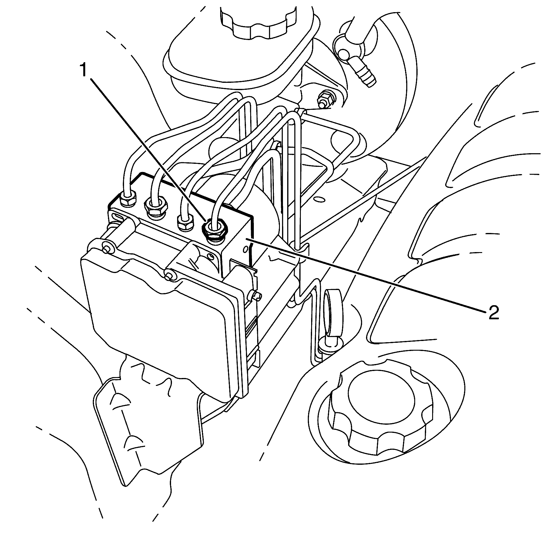
Important: Install a rubber cap or plug to the BPMV (2) in order to prevent fluid loss and contamination.
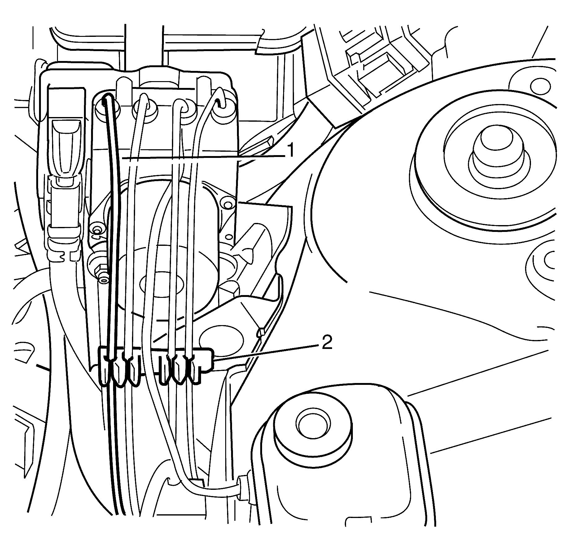


Important: The brake and fuel pipe heat shield (3) is retained by rivets (2). These rivets (2) must be drilled out during removal and replaced as per the installation procedure.
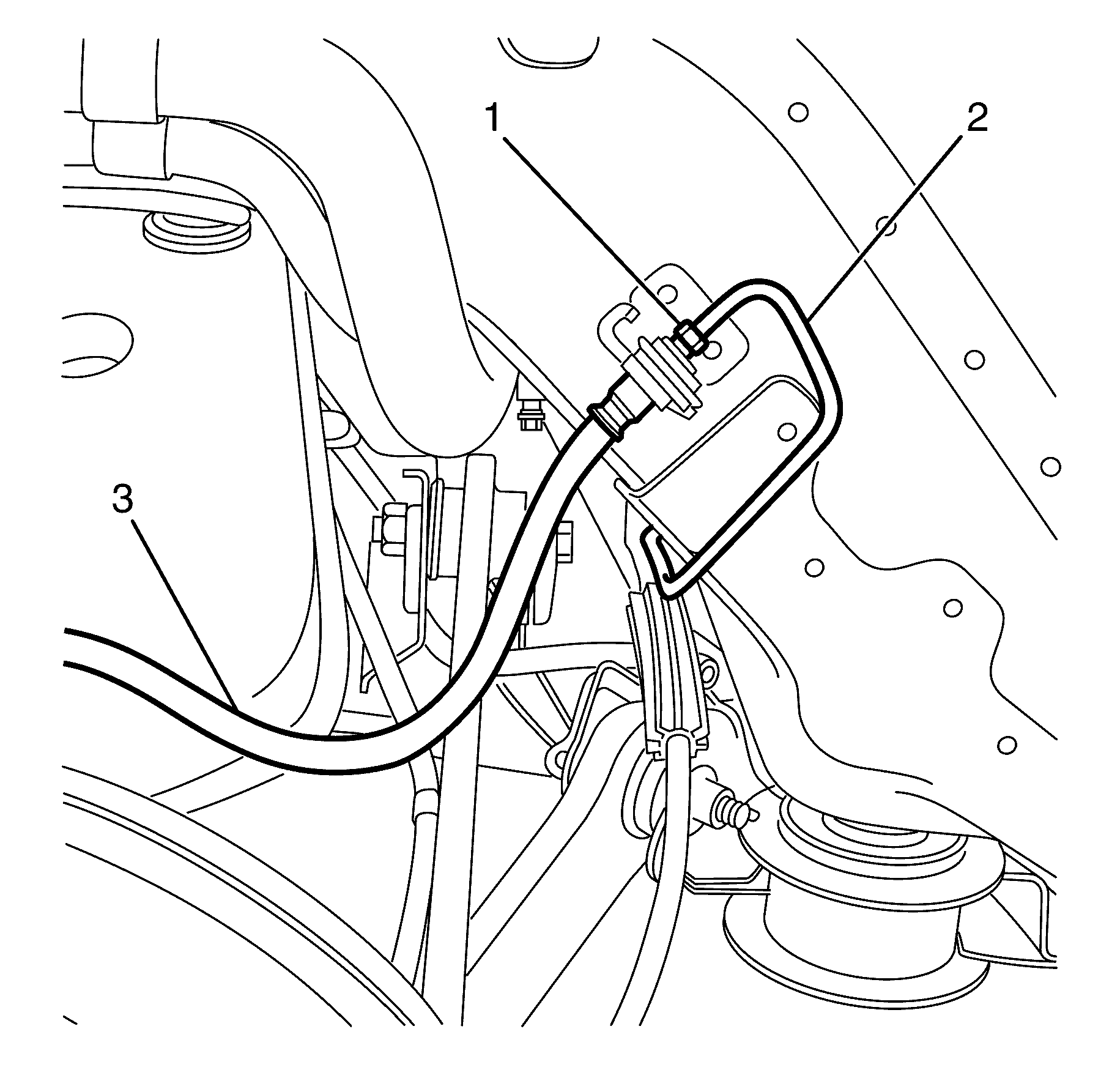
Important: Hold the brake hose (3) with a suitable whilst disconnecting the brake pipe fitting (1) to prevent damage to the brake pipe (2).
Important: Install a rubber cap or plug to the brake hose (3) in order to prevent brake fluid loss and contamination.

Important: The brake and fuel pipe retaining brackets (2) are retained by rivets (3). These rivets (3) must be drilled out during removal and replaced as per the installation procedure.

Important: Use a suitable tool to open the brake and fuel pipe retaining brackets (1) by detaching the brake and fuel pipe retaining bracket (1) clip.
Rear Brake Pipe Installation Procedure [dash ] Right
- Install the brake pipes (3) to the brake and fuel pipe retaining bracket rubber insulators (2).
- Close the brake and fuel pipe retaining brackets (1).
- Install the brake pipes (4) to the two brake and fuel pipe retaining bracket rubber insulators (1).
- Install the two brake and fuel pipe retaining brackets (2).
- Install the NEW brake and fuel pipe retaining bracket to chassis retaining rivets (3).
- Remove the rubber cap or plug from the brake hose (3).
- Connect the brake pipe fitting (1) to the brake hose (3).
- Lower the vehicle.
- Attach the brake pipe (1) to the locating clip (2).
- Remove the rubber cap or plug from the BPMV (2).
- Install the brake pipe (1) to the BPMV (2).
- Tighten the brake pipe fitting (1) to the brake hose (3).
- Tighten the brake pipe (1) to the BPMV (2).
- Raise the vehicle.
- Install the brake and fuel pipe splash shield (2) to the underbody.
- Install the brake and fuel pipe splash shield to chassis retaining nuts (1).
- Install the brake and fuel pipe heat shield (3).
- Attach the brake and fuel pipe heat shield clips (1).
- Install NEW brake and fuel pipe heat shield to bulkhead retaining rivets (2).
- Install the brake and fuel pipe heat shield to bulkhead retaining bolt (4).
- Install the engine. Refer to Engine Replacement - 3.6L or Customer Concern Verification Sheets .
- Install the front heat shield. Refer to Exhaust Front Heat Shield Replacement.
- Lower the vehicle.
- Install the brake and fuel pipe heat shield (3).
- Attach the brake and fuel pipe heat shield clips (1).
- Install NEW brake and fuel pipe heat shield to bulkhead retaining rivets (2).
- Install the brake and fuel pipe heat shield to bulkhead retaining bolt (4).
- Bleed the hydraulic brake system. Refer to Hydraulic Brake System Bleeding(Manual) or Hydraulic Brake System Bleeding(Pressure).


Do not fully tighten at this stage.


Do not fully tighten at this stage.
Notice: Refer to Fastener Notice in the Preface section.

Important: Hold the brake hose (3) with a suitable tool whilst connecting the brake pipe fitting (1) to prevent damage to the brake pipe (2).
Tighten
Tighten the brake pipe fitting to 15 Nm (11 lb ft).

Tighten
Tighten the brake pipe fitting to 15 Nm (11 lb ft).

Tighten
Tighten the nuts to 5 Nm (43 lb in).


Rear Brake Pipe Removal Procedure [dash ] Left
- Clean the master cylinder, brake lines and reservoir cap.
- Remove the master cylinder reservoir cap.
- Siphon the brake fluid out of the master cylinder reservoir (2) using the Customer Concern Verification Sheets .
- Remove the rear suspension sub frame assembly. Refer to Rear Frame Replacement.
- Place a clean suitable container under the brake pipe union (3).
- Disconnect the intermediate brake pipe (1) from the brake pipe union (3).
- Plug the brake pipe union (3).
- Disconnect the brake pipe fitting (1) from the brake hose (2).
- Plug the brake hose (2).
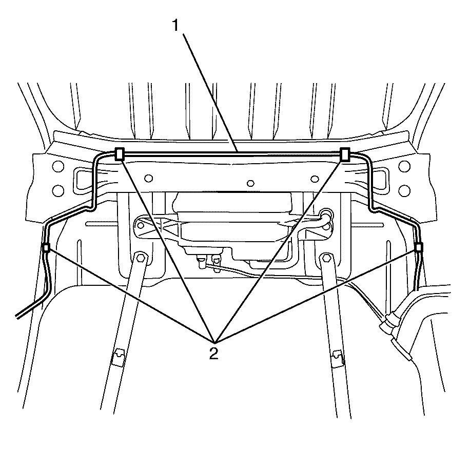
- Remove the brake pipe (1) from the brake pipe retaining clips (2).
Caution: Refer to Safety Glasses Caution in the Preface section.
Caution: Refer to Vehicle Lifting Caution in the Preface section.
Caution: Refer to Brake Dust Caution in the Preface section.
Caution: Refer to Brake Fluid Caution in the Preface section.
Caution: Refer to Brake Fluid Irritant Caution in the Preface section.
Notice: Refer to Adding Fluid to the Brake System Notice in the Preface section.
Notice: Refer to Brake Fluid Effects on Paint and Electrical Components Notice in the Preface section.

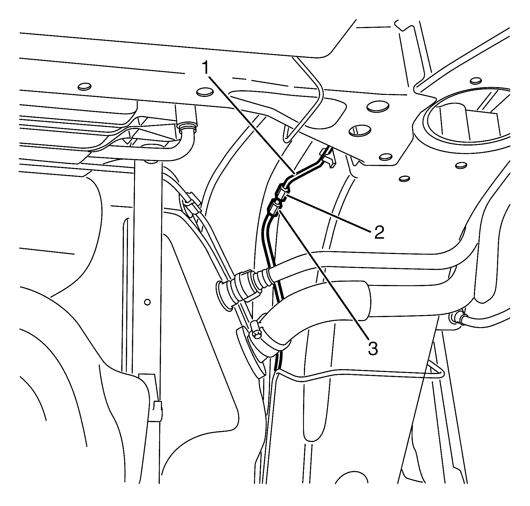
Important: Hold the brake pipe union (3) with a suitable tool whilst disconnecting the brake pipe fitting (2) to prevent damage to the brake pipe (1).
Important: Install a rubber cap or plug to the brake pipe union (3) in order to prevent brake fluid loss and/or contamination.
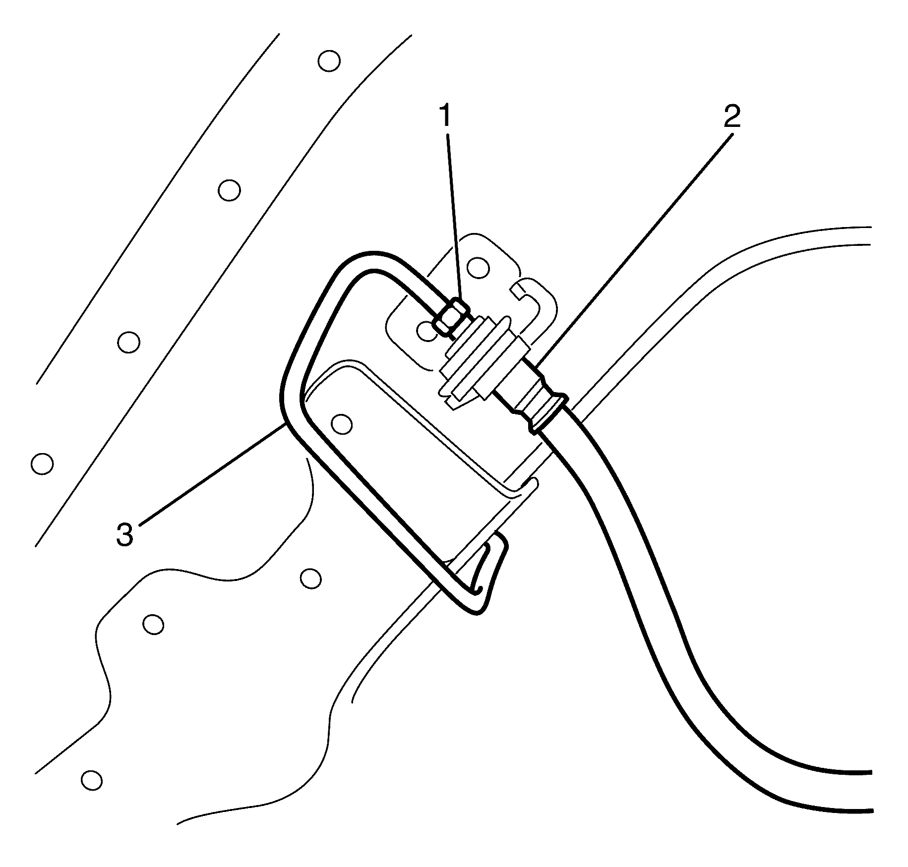
Important: Hold the brake hose (2) with a suitable tool whilst disconnecting the brake pipe fitting (1) to prevent damage to the brake pipe (3).
Important: Install a rubber cap or plug to the brake hose fitting end in order to prevent brake fluid loss and contamination.
Rear Brake Pipe Installation Procedure [dash ] Left
- Install the brake pipe (1) to the brake pipe retaining clips (2).
- Remove the rubber cap or plug from the brake hose (2).
- Connect the brake pipe fitting (1) to the brake hose (3).
- Remove the rubber cap or plug from the brake pipe union (2).
- Connect the brake pipe (1) to the brake pipe union (2).
- Tighten the brake pipe fitting (1) to the brake hose (3).
- Tighten the brake pipe (1) to the brake pipe union (2).
- Install the rear suspension sub frame assembly. Refer to Rear Frame Replacement.
- Bleed the hydraulic brake system. Refer to Hydraulic Brake System Bleeding(Manual) or Hydraulic Brake System Bleeding(Pressure).
Caution: Refer to Safety Glasses Caution in the Preface section.
Caution: Refer to Vehicle Lifting Caution in the Preface section.
Caution: Refer to Brake Dust Caution in the Preface section.
Caution: Refer to Brake Fluid Caution in the Preface section.
Caution: Refer to Brake Fluid Irritant Caution in the Preface section.
Notice: Refer to Adding Fluid to the Brake System Notice in the Preface section.
Notice: Refer to Brake Fluid Effects on Paint and Electrical Components Notice in the Preface section.


Do not fully tighten at this stage.

Do not fully tighten at this stage.
Notice: Refer to Fastener Notice in the Preface section.

Important: Hold the brake hose (2) with a suitable tool whilst connecting the brake pipe fitting (1) to prevent damage to the brake pipe (3) .
Tighten
Tighten the brake pipe fitting to 15 Nm (11 lb ft).

Important: Hold the brake pipe union (2) with a suitable tool whilst connecting the brake pipe fitting (3) to prevent damage to the brake pipe (2).
Tighten
Tighten the brake pipe fitting to 15 Nm (11 lb ft).
