Brake Pedal Assembly Replacement RHD
Removal Procedure
- Remove the instrument panel lower trim panel assembly. Refer to Knee Bolster Replacement.
- Remove the instrument panel lower right trim plate assembly. Refer to Instrument Panel Insulator Panel Replacement - Right Side.
- Remove the instrument panel lower trim panel retainer. Refer to Instrument Panel Retainer Replacement.
- Remove the master cylinder from the vehicle. Refer to Master Cylinder Replacement.
- Remove the vacuum hose and check valve from the vacuum brake booster. Refer to Power Brake Booster Inlet Hose Replacement.
- Remove the brake pedal position sensor. Refer to Stop Lamp Switch Replacement.
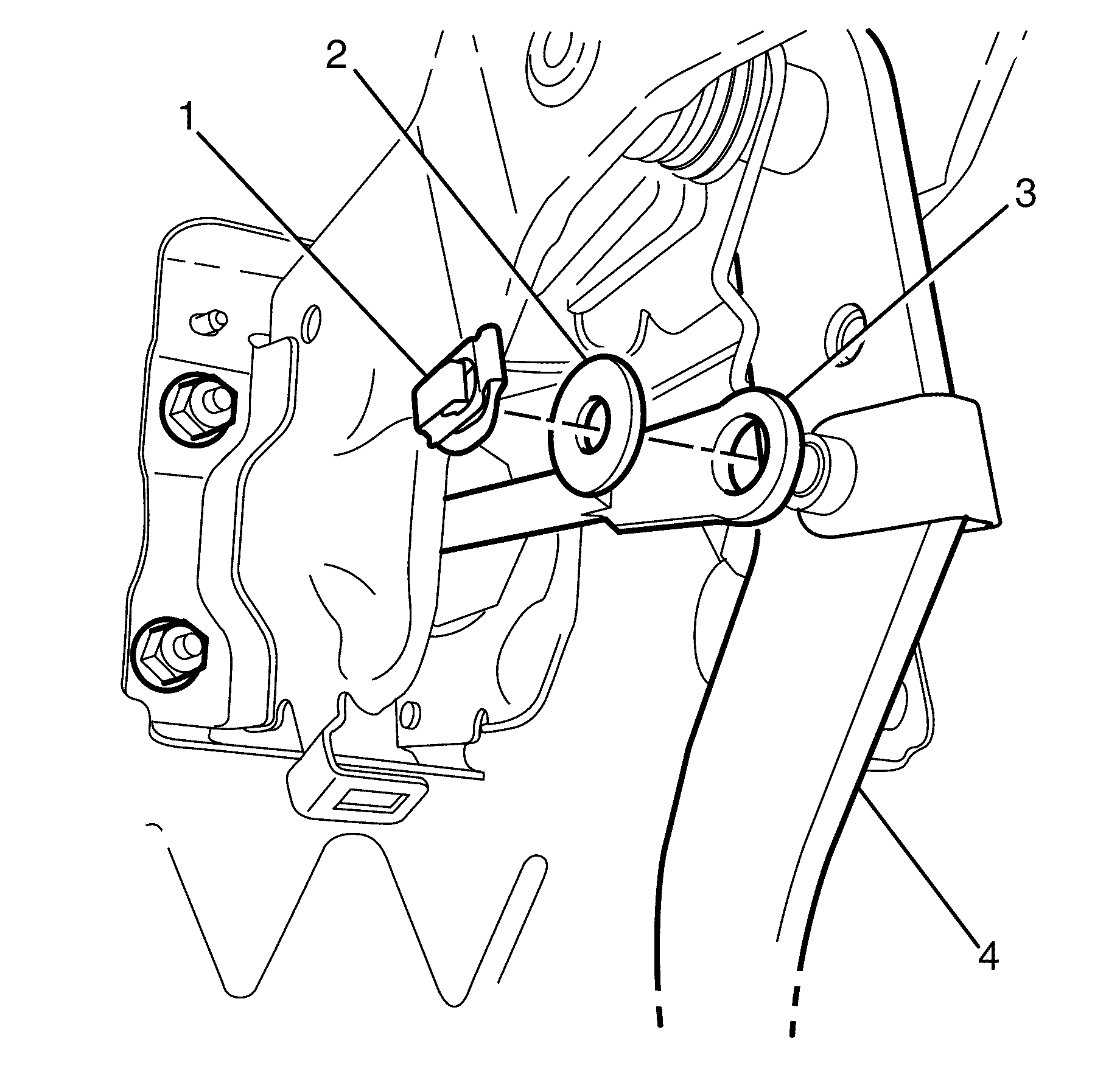
- Remove the brake pedal pushrod retaining clip (1), washer (2) and the brake pedal pushrod (3) from the brake pedal (4).
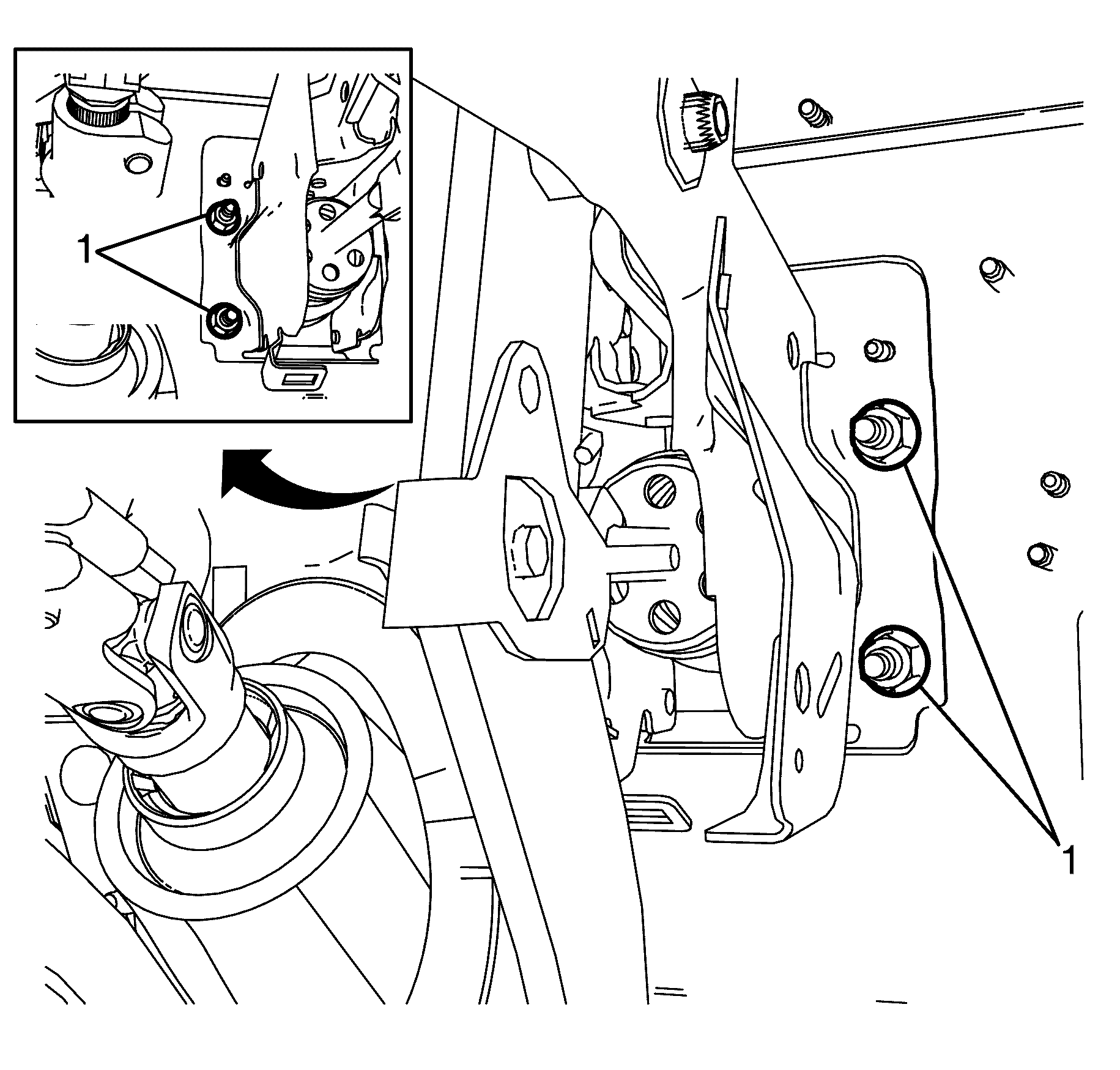
- Remove the vacuum brake booster to brake pedal support bracket retaining nuts (1).
- Remove the vacuum brake booster from the vehicle.
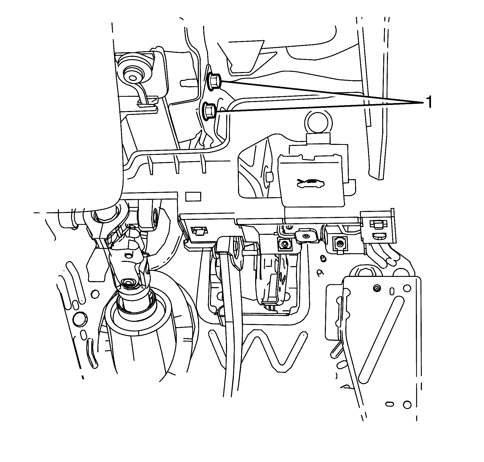
- Remove the two brake pedal bracket assembly to instrument panel crossmember retaining bolts (1).
- Remove the brake pedal assembly from under the instrument panel.
Caution: Refer to Brake Fluid Caution in the Preface section.
Caution: Refer to Brake Fluid Irritant Caution in the Preface section.
Notice: Refer to Adding Fluid to the Brake System Notice in the Preface section.
Notice: Refer to Brake Fluid Effects on Paint and Electrical Components Notice in the Preface section.


Important: From the engine compartment, pull the vacuum brake booster forward to release the four studs from the bulkhead and brake pedal support bracket.

Important: Lower the brake pedal assembly rear end first to aid in removal.
Installation Procedure
- Install the brake pedal assembly to the instrument panel crossmember.
- Install the two brake pedal bracket assembly to instrument panel crossmember retaining bolts (1).
- With the aid of an assistant install the vacuum brake booster from the engine compartment.
- Install the vacuum brake booster to brake pedal support bracket retaining nuts (1).
- Install the push rod (3), washer (2) and retaining clip (1) to the brake pedal assembly (4).
- Tighten the two brake pedal bracket assembly to cross car beam retaining bolts (1).
- Install the brake pedal position sensor. Refer to Stop Lamp Switch Replacement.
- Install the vacuum hose and check valve to the vacuum brake booster. Refer to Power Brake Booster Inlet Hose Replacement.
- Install the master cylinder. Refer to Master Cylinder Replacement.
- Bleed the braking system. Refer to Hydraulic Brake System Bleeding.
- Install the instrument panel lower trim panel retainer. Refer to Instrument Panel Insulator Panel Replacement - Right Side.
- Install the instrument panel lower trim panel assembly. Refer to Knee Bolster Replacement.
- Road test the vehicle to inspect correct brake, stop lamp and cruise control operation.
Caution: Refer to Brake Fluid Caution in the Preface section.
Caution: Refer to Brake Fluid Irritant Caution in the Preface section.
Notice: Refer to Adding Fluid to the Brake System Notice in the Preface section.
Notice: Refer to Brake Fluid Effects on Paint and Electrical Components Notice in the Preface section.
Important: Raise the brake pedal assembly front end first to aid in installation.

DO NOT fully tighten at this stage.
Important: Make sure the vacuum brake booster's four studs are correctly located in the bulkhead and brake pedal support bracket.
Notice: Refer to Fastener Notice in the Preface section.

Tighten
Tighten the nuts to 22 Nm (16 lb ft).


Tighten
Tighten the bolts to 23 Nm (17 lb ft).
