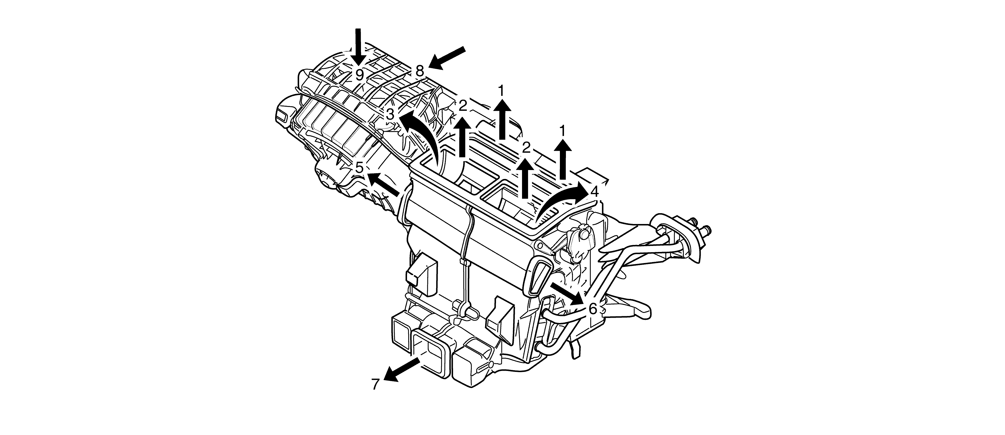
The Air Delivery Description and Operation is divided into 6 primary areas:
| • | HVAC Control Components. |
HVAC Control Components
HVAC Control Module
The HVAC control module is a GMLAN device that interfaces between the operator
and the HVAC System to maintain air temperature and distribution settings. The battery
positive voltage circuit provides power that the control module uses for keep alive
memory (KAM). The Body Control Module (BCM), which is the vehicle power mode master,
provides a device on signal. The control module supports the following features:
Feature
| Availability
|
Purge
| Yes
|
Personalisation
| Yes
|
Actuator Calibration
| Yes
|
Personalisation
If the personalisation feature for climate control is selected through the radio,
the HVAC control module will receive information that defines the current driver of
the vehicle from the BCM module through GMLAN communication. This information will
be stored inside the HVAC control module memory. When a different key is selected,
the HVAC control module will recall the appropriate driver settings. Upon a battery
reset, the HVAC control module shall also set the driver ID to Driver 1. The HVAC
system will memorise the following system configurations for up to 2 unique drivers:
| • | Passenger set temperature |
| • | A/C compressor request, auto ON or A/C OFF |
Mode Actuator
The mode actuator consists of a DC drive motor, reduction gears, printed circuit
board (PCB) and a photo electric cell. The DC motors are provided with a supply voltage
of 12 Volts from the HCM. The photo interrupter counts the revolutions of the DC motor
drive shaft, these counts are then used by the HCM for reference to the actuator position.
When the ignition is cycled from OFF to ON the mode and temperature actuators (doors)
are driven to their 0% positions which for the temperature door is full cold and the
mode doors are to the closed position. The actuators are then driven to the previous
settings before the ignition was turned OFF by using the same amount of counts recorded.
Recirculation Actuator
The recirculation actuator consists of a DC drive motor, reduction gears, printed
circuit board (PCB) and a photo electric cell. The DC motors are provided with a supply
voltage of 12 Volts from the HCM. The photo interrupter counts the revolutions of
the DC motor drive shaft, these counts are then used by the HCM for reference to the
actuator position. When the ignition is cycled from OFF to ON the mode and temperature
actuators (doors) are driven to their 0% positions which for the temperature door
is full cold and the mode doors are to the closed position. The actuators are then
driven to the previous settings before the ignition was turned OFF by using the same
amount of counts recorded.
Blower Motor Control Processor
The blower motor control processor is an interface between the HVAC control
module and the blower motor. The blower motor speed control, blower motor supply voltage
and ground circuits enable the control processor to operate. The HVAC control module
provides a pulse width modulation (PWM) signal to the control processor in order to
command the blower motor speed. The control processor uses the blower motor ground
as a low side control to adjust the blower motor speed.
Air Speed
The blower motor forces air to circulate within the vehicle's interior. The
vehicle operator determines the blower motors speed by placing the blower motor switch
in a desired speed position or by selecting automatic operation. In manual operation,
once a blower speed is selected, the blower speed remains constant, until a new speed
is selected. In automatic operation, the HVAC control module will determine what blower
speed is necessary in order to achieve or maintain a desired temperature.
As the requested blower speed increases, the following conditions occur:
| • | The HVAC control module increases the amount of time that the blower motor
speed control circuit is modulated to ground. |
| • | The voltage and duty cycle, measured between the blower motor speed control
circuit and ground, decrease. |
As the requested blower speed decreases, the following conditions occur:
| • | The HVAC control module decreases the amount of time that the blower motor
speed control circuit is modulated to ground. |
| • | The voltage and duty cycle, measured between the blower motor speed control
circuit and ground, increase. |
Air Distribution
The HVAC control module controls the mode actuator in order to distribute airflow
to a desired outlet. The mode switch provides the vehicle operator with the ability
to override the automatic setting. When the mode door is moved to the defrost position,
the A/C compressor piston stroke is increased and the recirculation actuator will
be moved to the outside air position.
Important: The HVAC system allows air to the outboard
face outlets in all air distribution modes. This allows air to be circulated higher
in the cabin under any operating condition. The face outlets have three operating
positions, open, side window deflector and closed. To reduce air from these outlets,
the individual outlet thumbwheel must be turned to the OFF or side window deflector
position.
HVAC Air Flow Direction
HVAC Air Flow Direction


