For 1990-2009 cars only
Tools Required
| • | J 42492-A (KM-421-A) Timing Belt Adjuster |
| • | J 45059 Angle Meter |
| • | KM-470-B Angular Torque Gage |
Removal Procedure
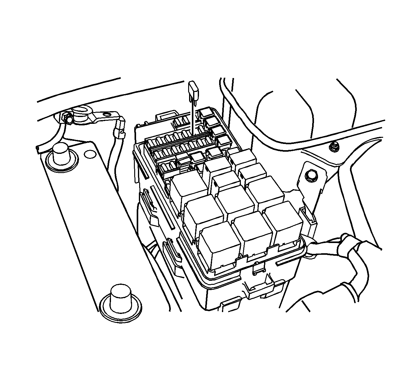
- Remove the fuel pump fuse.
- Start the engine. After it stalls, crank the engine for 10 seconds to rid the fuel system of fuel pressure.
- Disconnect the negative battery cable.
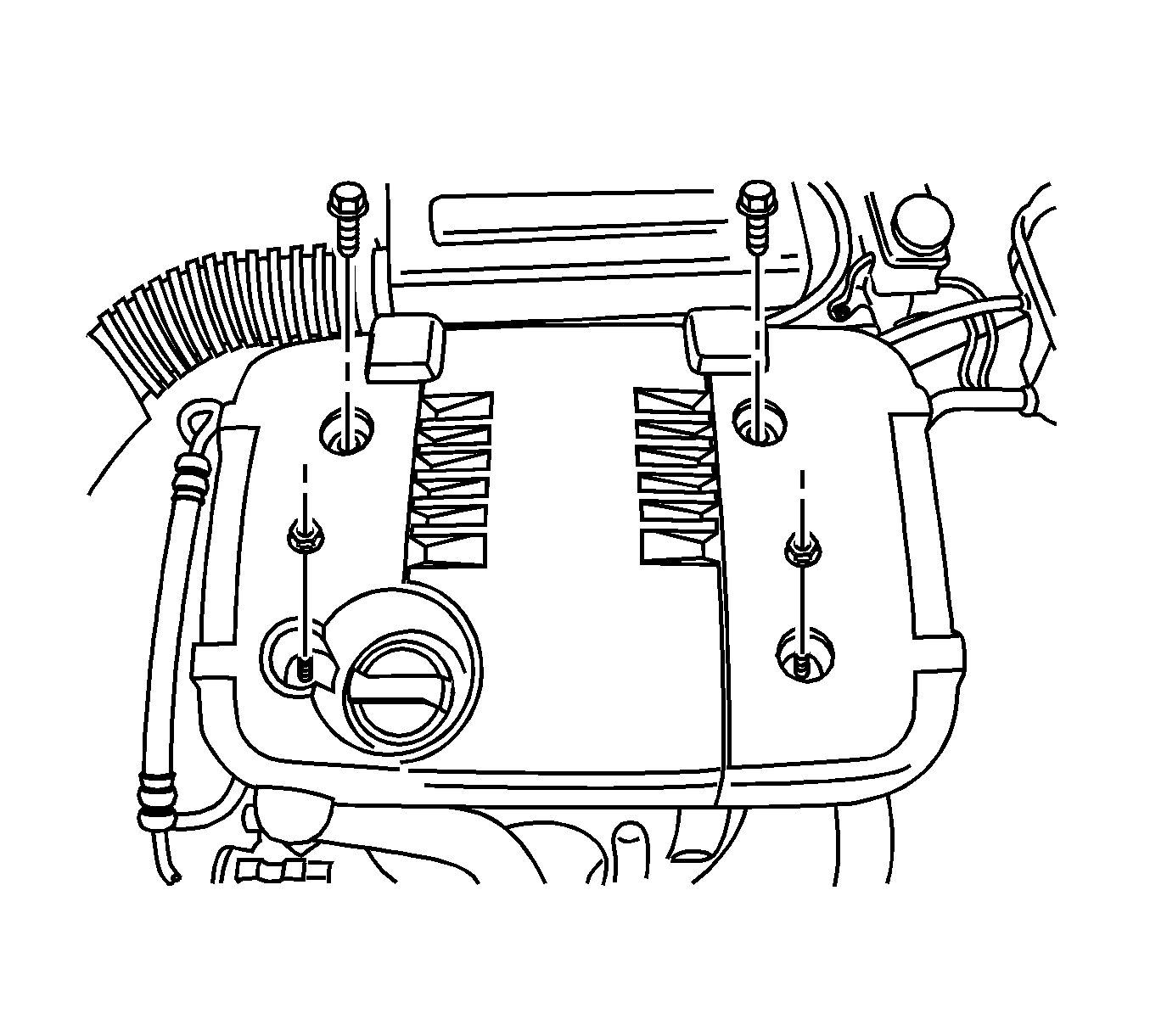
- Remove the engine cover.
- Remove the air cleaner assembly. Refer to Air Cleaner Assembly Replacement .
- Drain the engine coolant. Refer to Cooling System Draining and Filling .
- Disconnect the engine coolant temperature (ECT) sensor electrical connector.
- Disconnect the purge solenoid valve connector.
- Disconnect the generator connector.
- Disconnect the A/C pressure switch connector.
- Disconnect the idle air control valve (IACV) connector.
- Disconnect the throttle position sensor (TPS) electrical connector.
- Disconnect the manifold air pressure (MAP) sensor electrical connector.
- Disconnect the oil pressure switch electrical connector.
- Disconnect the throttle body cable.
- Remove the generator upper bracket.
- Remove the all the vacuum hoses from the intake manifold including brake booster vacuum hose.
- Remove the brake vacuum tube.
- Remove the purge solenoid tube from the throttle body.
- Remove the positive crankcase ventilation (PCV) hose from the camshaft cover.
- Remove the ignition cables from the spark plugs.
- Remove the direct ignition coil and the bracket from the cylinder head. Refer to Ignition Coil Replacement .
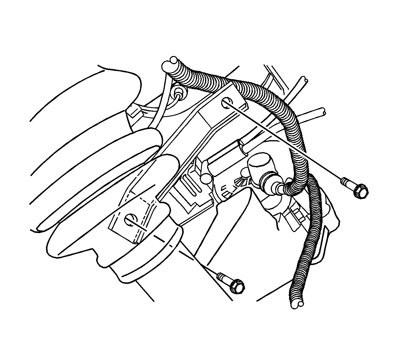
- Remove the intake manifold support bracket bolts.
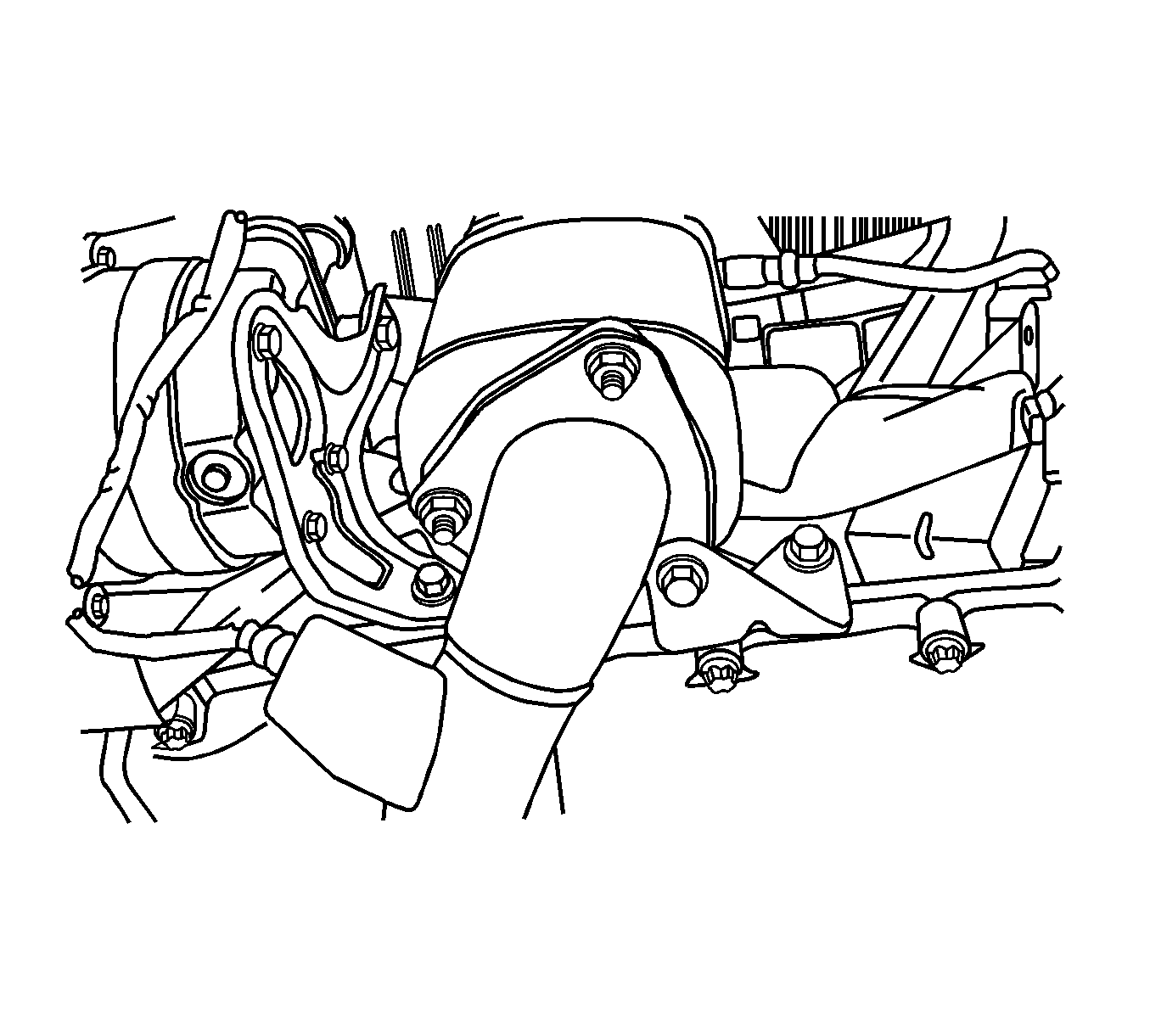
- Remove the exhaust flex pipe retaining nuts at the exhaust manifold studs.
- Remove the coolant upper hose.
- Remove the camshaft cover. Refer to Valve Rocker Arm Cover Replacement .
- Remove the timing belt. Refer to Timing Belt Replacement .
- Remove the camshaft gears. Refer to Camshaft Gear Replacement .
- Remove the cylinder head bolts gradually in the sequence shown and remove the cylinder head.
- Remove the cylinder head gasket.
- Clean the gasket surfaces on the cylinder head and the engine block. Refer to Cylinder Head Cleaning and Inspection .
Caution: Refer to Battery Disconnect Caution in the Preface section.
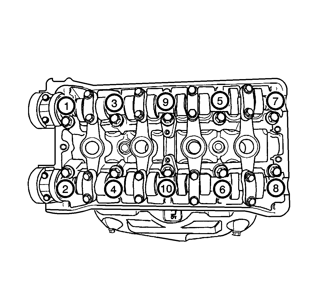
Notice: Use extreme care when removing the cylinder head to prevent any engine oil , dirt, or coolant from entering the engine. Damage to the engine could result.
Installation Procedure
- Install the new cylinder head gasket.
- Install the intake/exhaust manifold to the cylinder head. Refer to Intake Manifold Replacement and Exhaust Manifold Removal .
- Install the cylinder head bolts gradually in the sequence shown using J 45059 or KM-470-B .
- Install the camshaft gears. Refer to Camshaft Gear Replacement .
- Install the timing belt. Refer to Timing Belt Replacement .
- Install the camshaft cover. Refer to Valve Rocker Arm Cover Replacement .
- Install the coolant upper hose.
- Install the exhaust flex pipe retaining nuts at the exhaust manifold flange.
- Install the intake manifold support bracket bolts.
- Install the direct ignition coil and the bracket to the cylinder head. Refer to Ignition Coil Replacement .
- Connect the ignition wires to the spark plugs.
- Install the positive crankcase ventilation (PCV) hose to the camshaft cover.
- Install the purge solenoid tube to the throttle body.
- Install the brake vacuum tube.
- Connect all the disconnected vacuum hoses and the brake booster vacuum hose at the intake manifold.
- Install the generator upper bracket.
- Connect the throttle body cable.
- Connect the oil pressure switch electrical connector.
- Connect the manifold air pressure (MAP) sensor electrical connector.
- Connect the throttle position sensor (TPS) electrical connector.
- Connect the idle air control valve (IACV) connector.
- Connect the A/C pressure switch connector.
- Connect the generator connector.
- Connect the purge solenoid valve connector.
- Connect the engine coolant temperature (ECT) sensor electrical connector.
- Install the right engine mount. Refer to Engine Mount Replacement .
- Refill the engine cooling system. Refer to Cooling System Draining and Filling .
- Install the air cleaner assembly. Refer to Air Cleaner Assembly Replacement .
- Install the engine cover.
- Install the fuel pump fuse.
- Connect the negative battery cable.
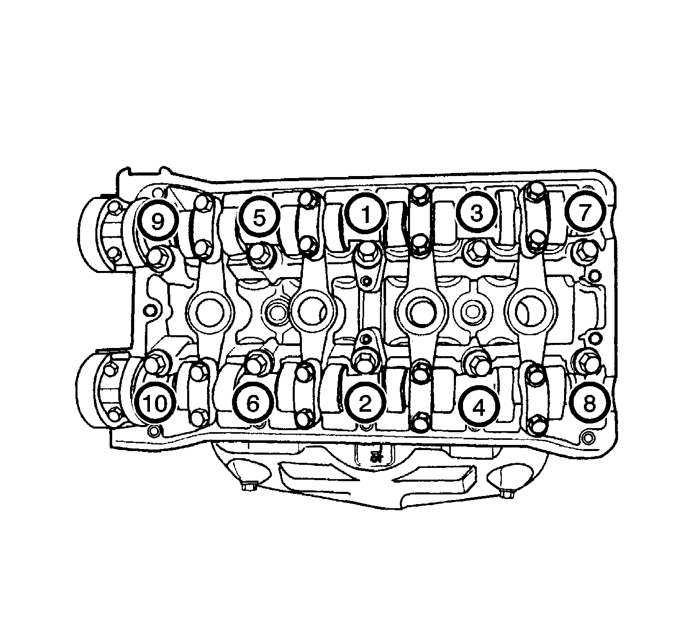
Notice: Refer to Fastener Notice in the Preface section.
Tighten
Tighten the cylinder head bolts to 25 N·m (18 lb ft) and retighten the cylinder head bolts 190 degrees.

Tighten
Tighten the catalytic converter to exhaust manifold flange nuts to 35 N·m (26 lb ft).

Tighten
Tighten the intake manifold support bracket upper bolt to 25 N·m (18 lb ft).
Tighten
Tighten the intake manifold support bracket lower bolt to 45 N·m (33 lb ft).


Caution: Refer to Battery Disconnect Caution in the Preface section.
