For 1990-2009 cars only
Tools Required
J 45404 Transmission Indicator Alignment Tool
Removal Procedure
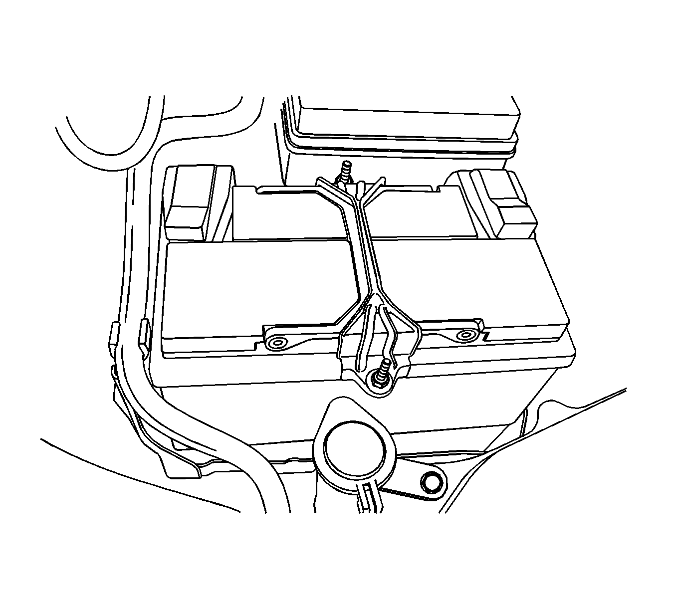
- Remove the battery and tray. Refer to Battery Tray Replacement .
- Apply the parking brake and place the control shift lever in neutral (N).
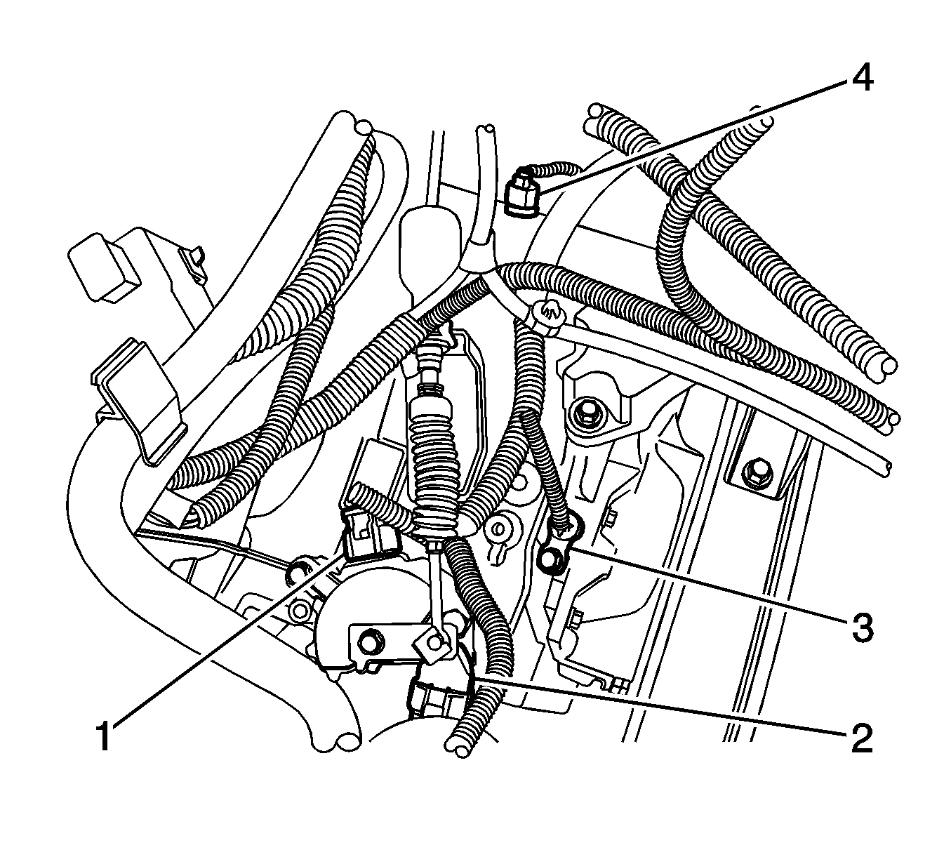
- Disconnect the transmission range (TR) switch electrical connector (1) and the transaxle electrical connector (2).
- Disconnect the cable from the TR switch lever. Refer to Shift Control Cable Replacement .
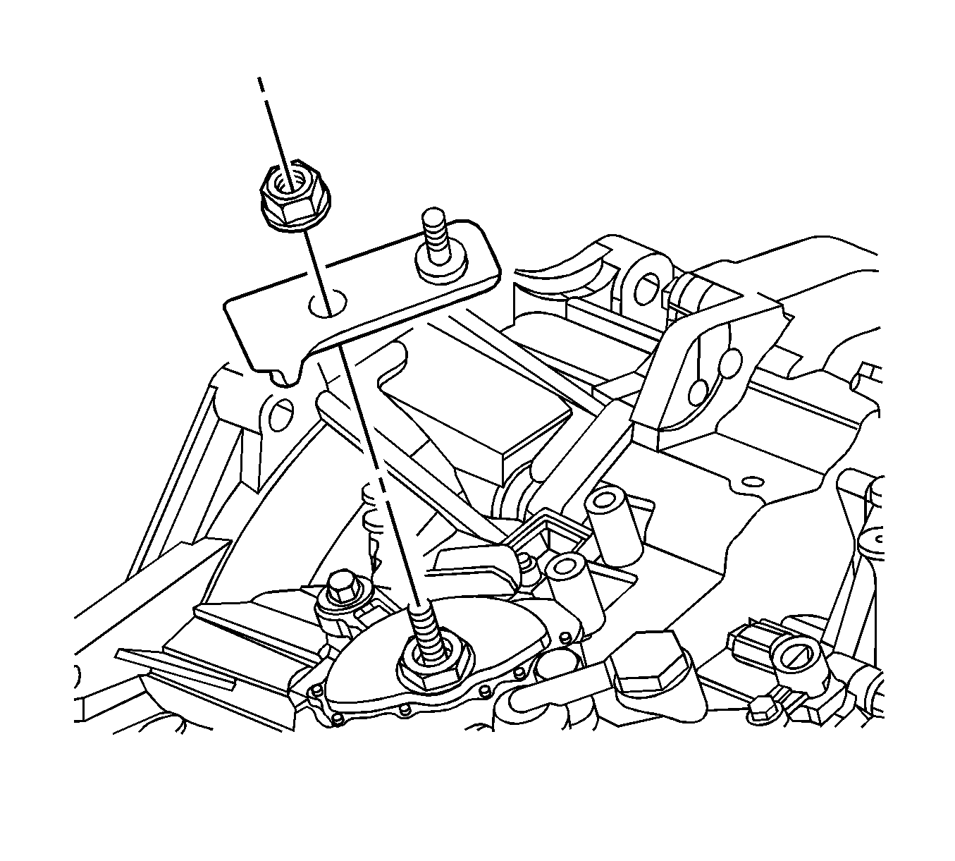
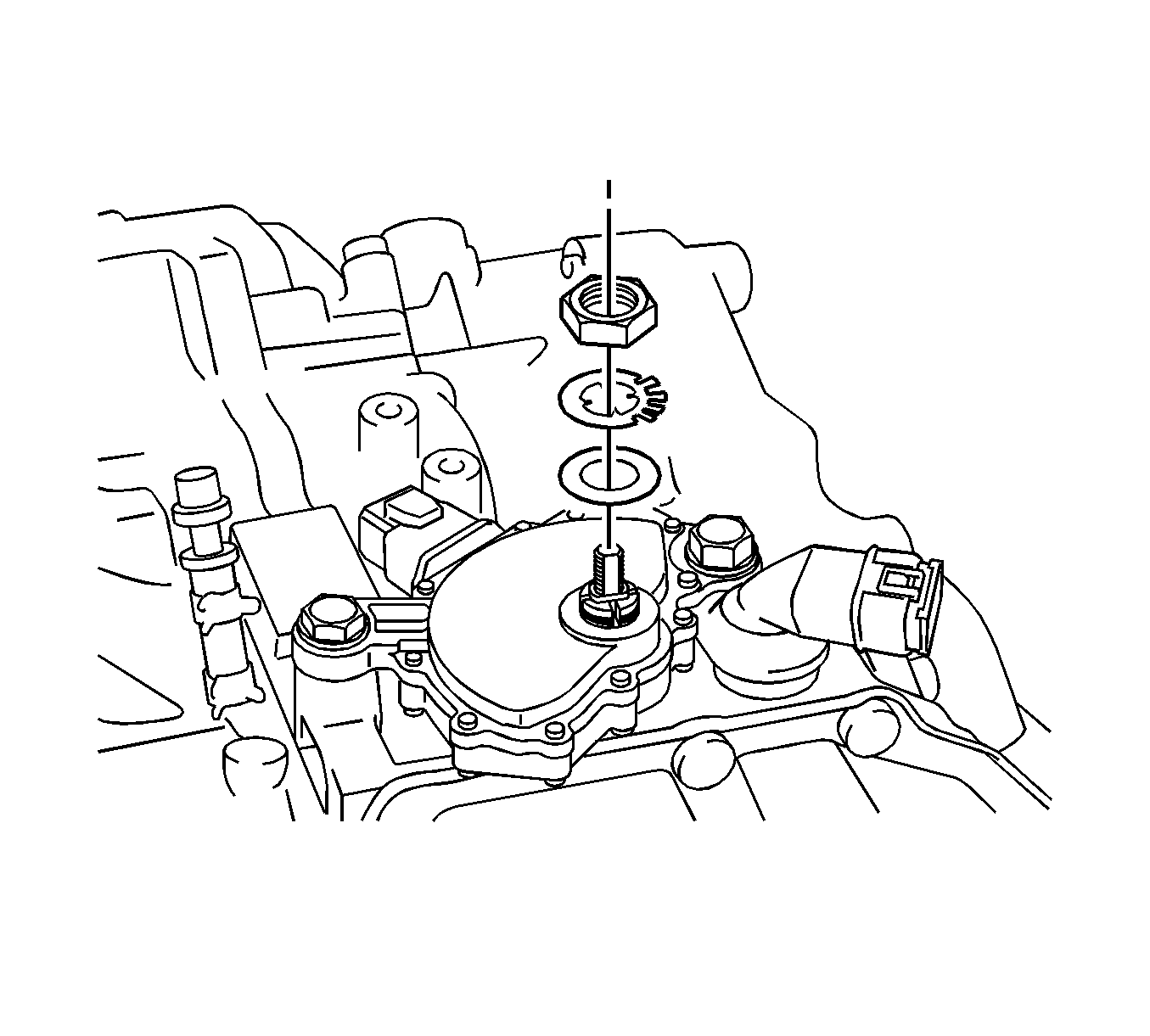
- Remove the TR switch lever nut and lever.
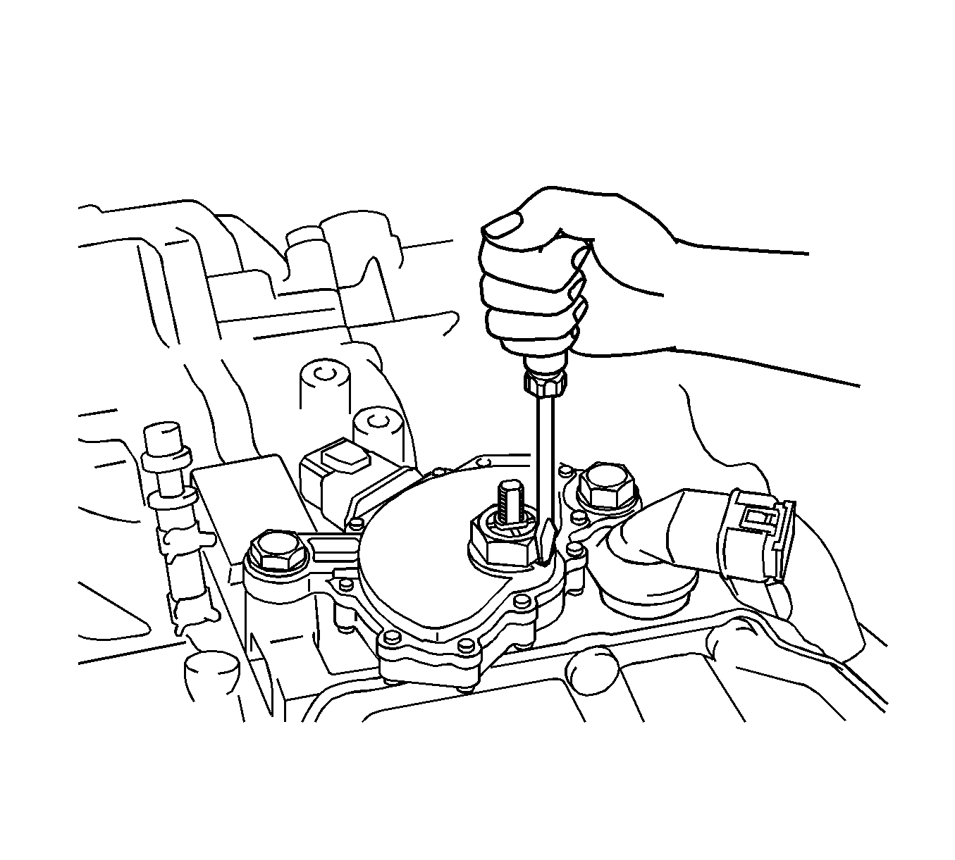
- Using a screwdriver, bend the lockwasher tabs down away from the manual shaft nut.
- Remove the nut, lock tab washer, and flat washer.
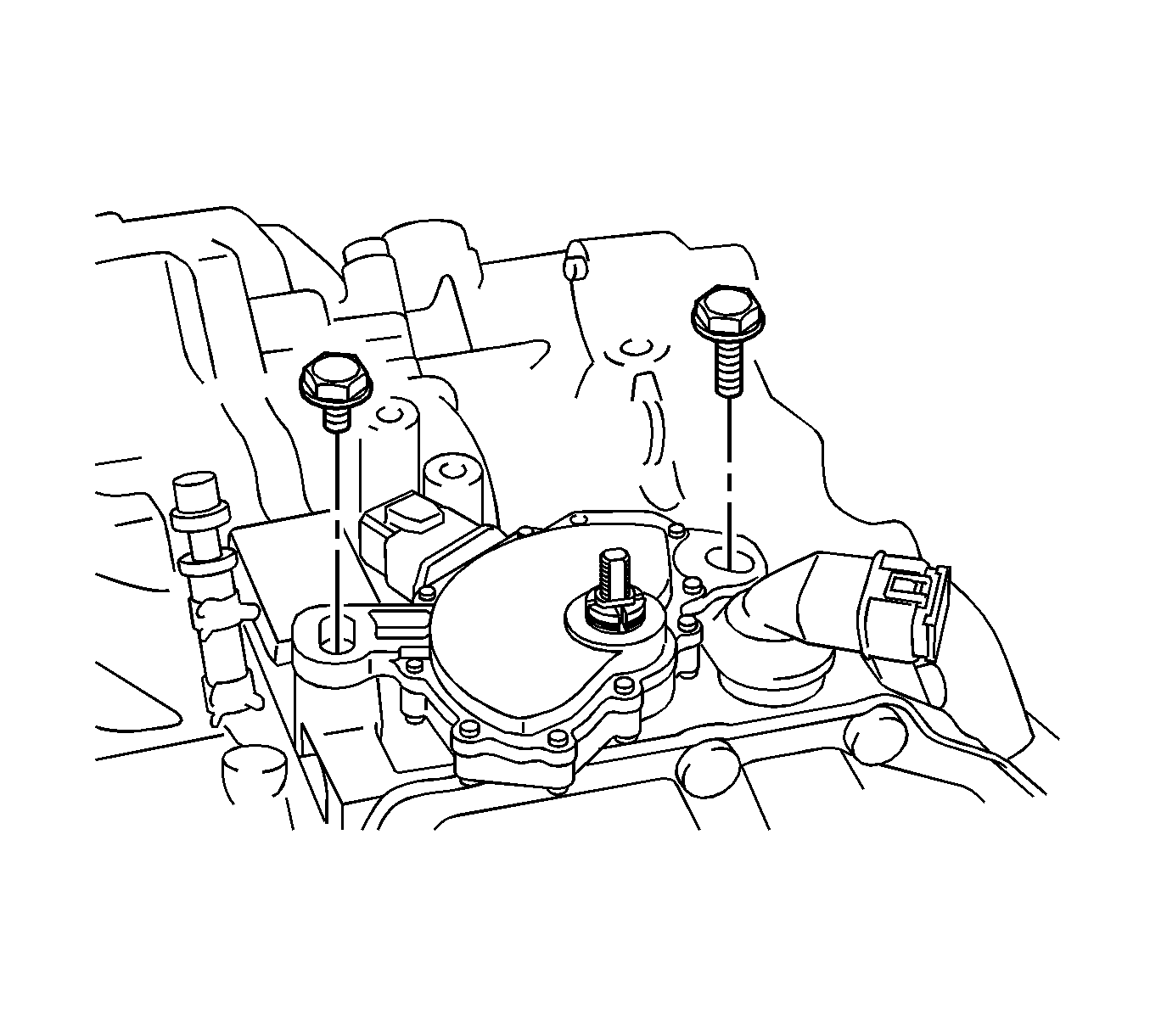
- Remove the TR switch bolts.
- Remove the TR switch.
Important: The transaxle manual shaft must be in neutral (N) position prior to reinstalling the switch.
Installation Procedure
- Install the TR switch to the manual shaft lever.
- Install the bolts. Hand tighten ONLY at this time.
- Install the flat washer, lock tab washer, and nut.
- Ensure the manual shaft is in neutral (N) position.
- Bend the lock washer tabs up to secure the nut.
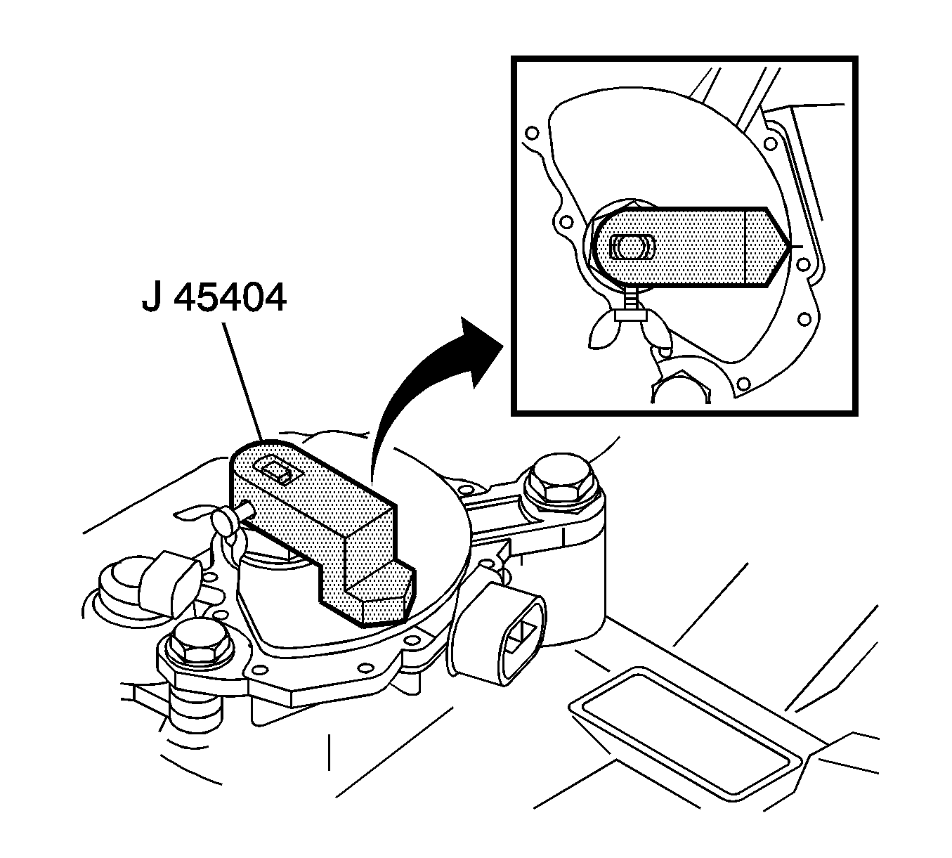
- Install the J 45404 to the manual shaft and rotate the TR switch until the neutral base line on the switch lines up with the indicator line on the J 45404 .
- Install the TR switch bolts.
- Remove the J 45404 from the manual shaft.
- Install the TR switch lever and nut.
- Install the cable to TR switch lever and adjust the cable. Refer to Shift Control Cable Replacement .
- Connect the electrical connector (1, 2).
- Install the battery and tray. Refer to Battery Tray Replacement .
- After adjusting the TR switch, verify the engine only starts in park (P) or neutral (N). If the engine starts in any other position, re-adjust the switch.

Notice: Refer to Fastener Notice in the Preface section.

Tighten
Tighten the TR switch nut to 7 N·m (62 lb in).

Tighten
Tighten the TR switch bolts to 25 N·m (18 lb ft).

Tighten
Tighten the TR lever nut to 16 N·m (12 lb ft).


