For 1990-2009 cars only
Special Tools
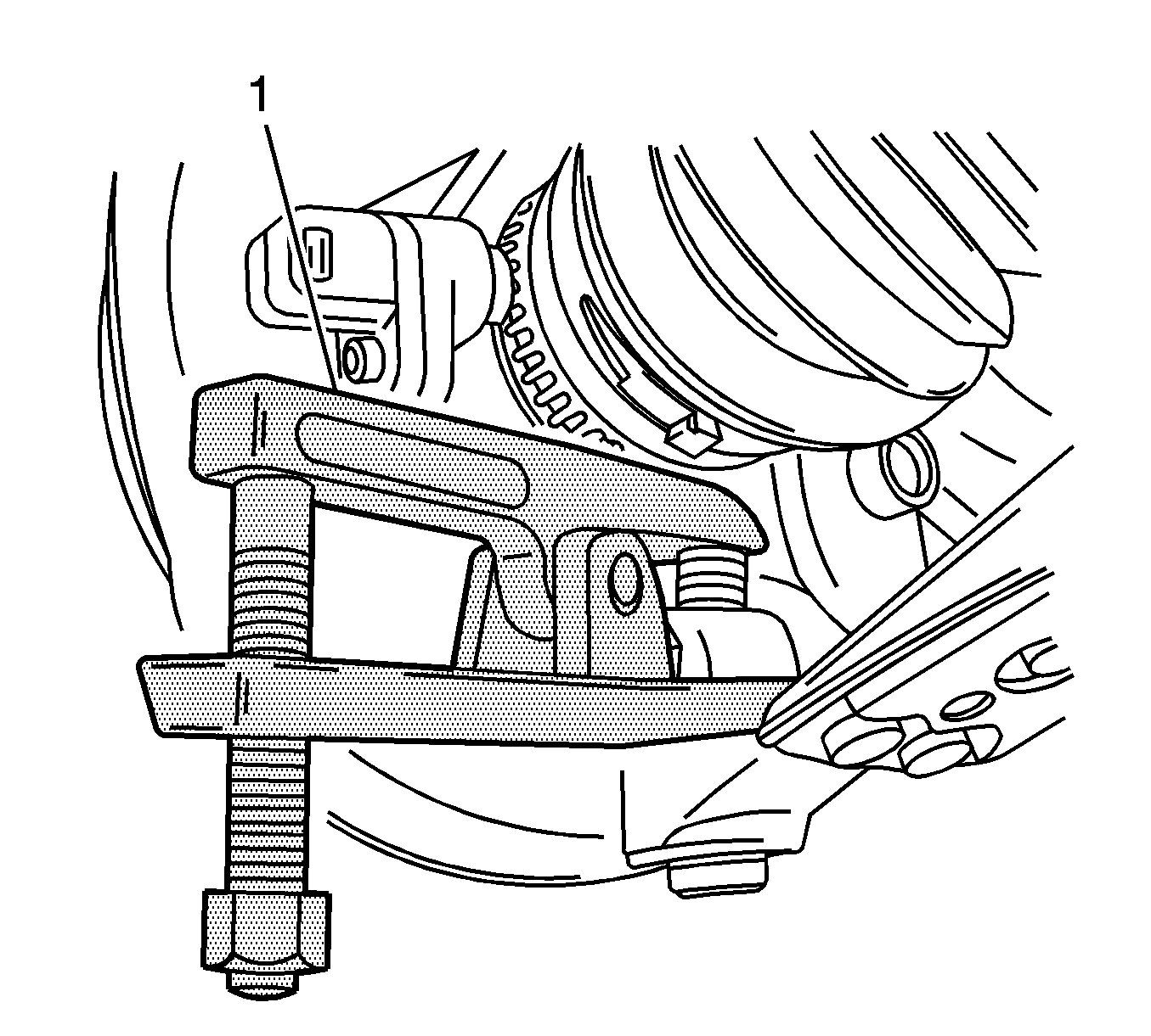
KM-507-C Ball Joint Remover
Removal Procedure
- Raise and suitably support the vehicle. Refer to Lifting and Jacking the Vehicle.
- Remove the wheel. Refer to Tire and Wheel Removal and Installation.
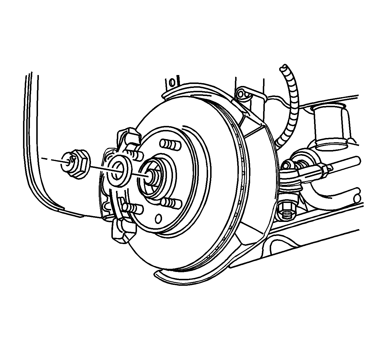
- Remove the caulking nut from the axle shaft.
- Remove the brake caliper from the rotor. Support the caliper so it does not hang from the hydraulic brake hose. Refer to Front Brake Caliper Replacement.
- Remove the outer tie rod from the knuckle assembly. Refer to Steering Linkage Outer Tie Rod Replacement.
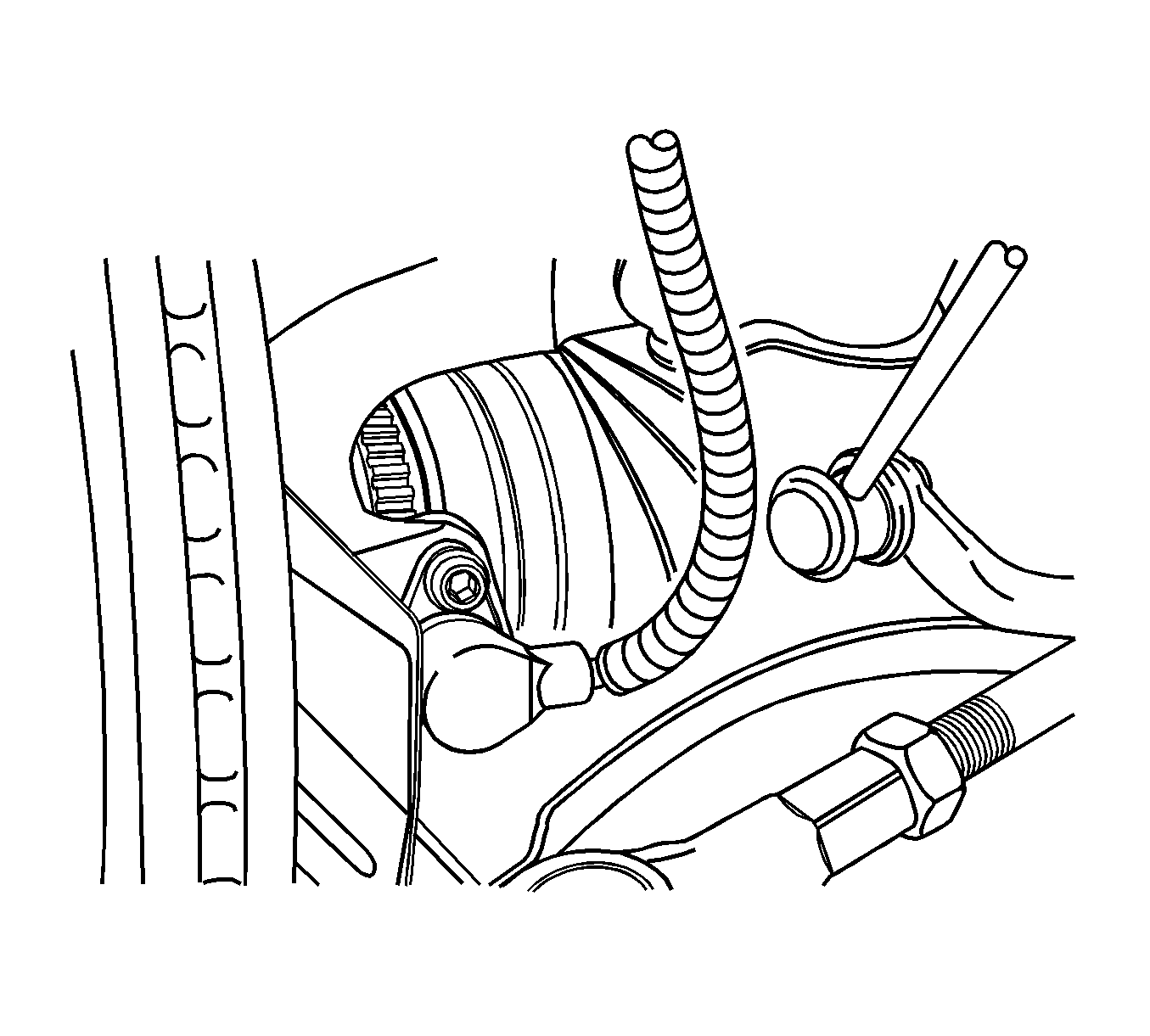
- On vehicles equipped with the antilock braking system (ABS), disconnect the ABS speed sensor electrical connection from the knuckle.
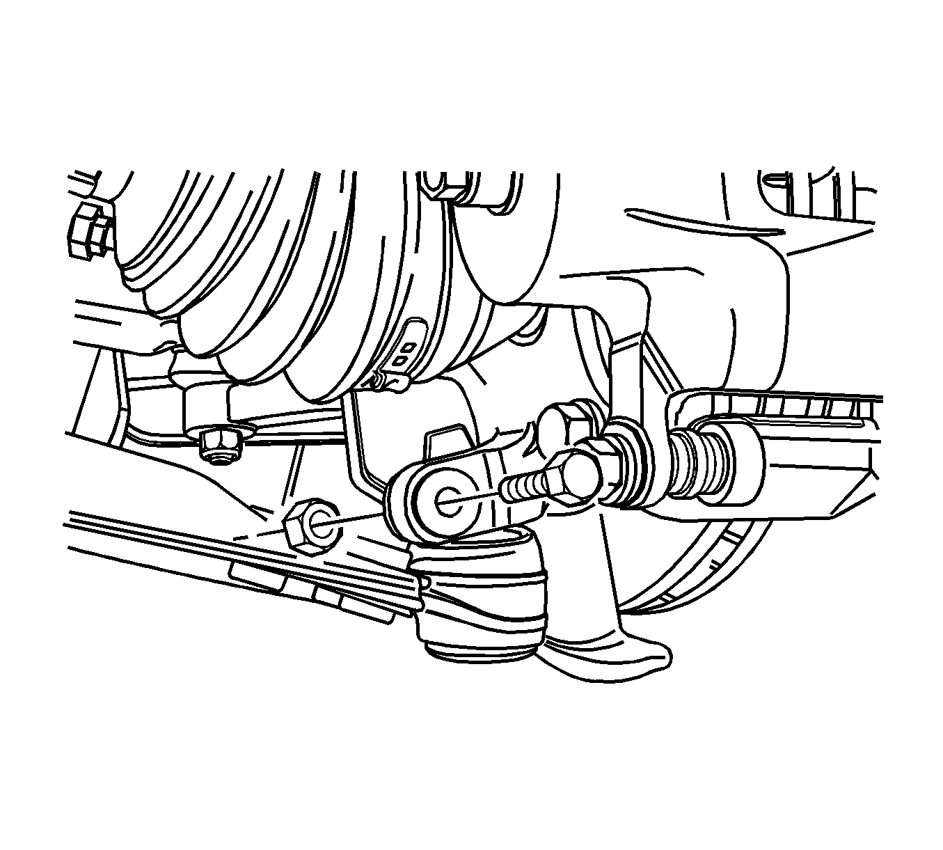
- Remove the ball joint pinch bolt and the nut.
- Separate the knuckle from the ball joint using the KM-507-C (1).
- Remove the nuts from the bolts that connect the knuckle assembly to the strut assembly.
- Support the drive axle.
- Separate the drive axle shaft from the wheel hub.
- Remove the bolts that connect the knuckle assembly to the strut assembly.
- Remove the knuckle assembly from the vehicle.
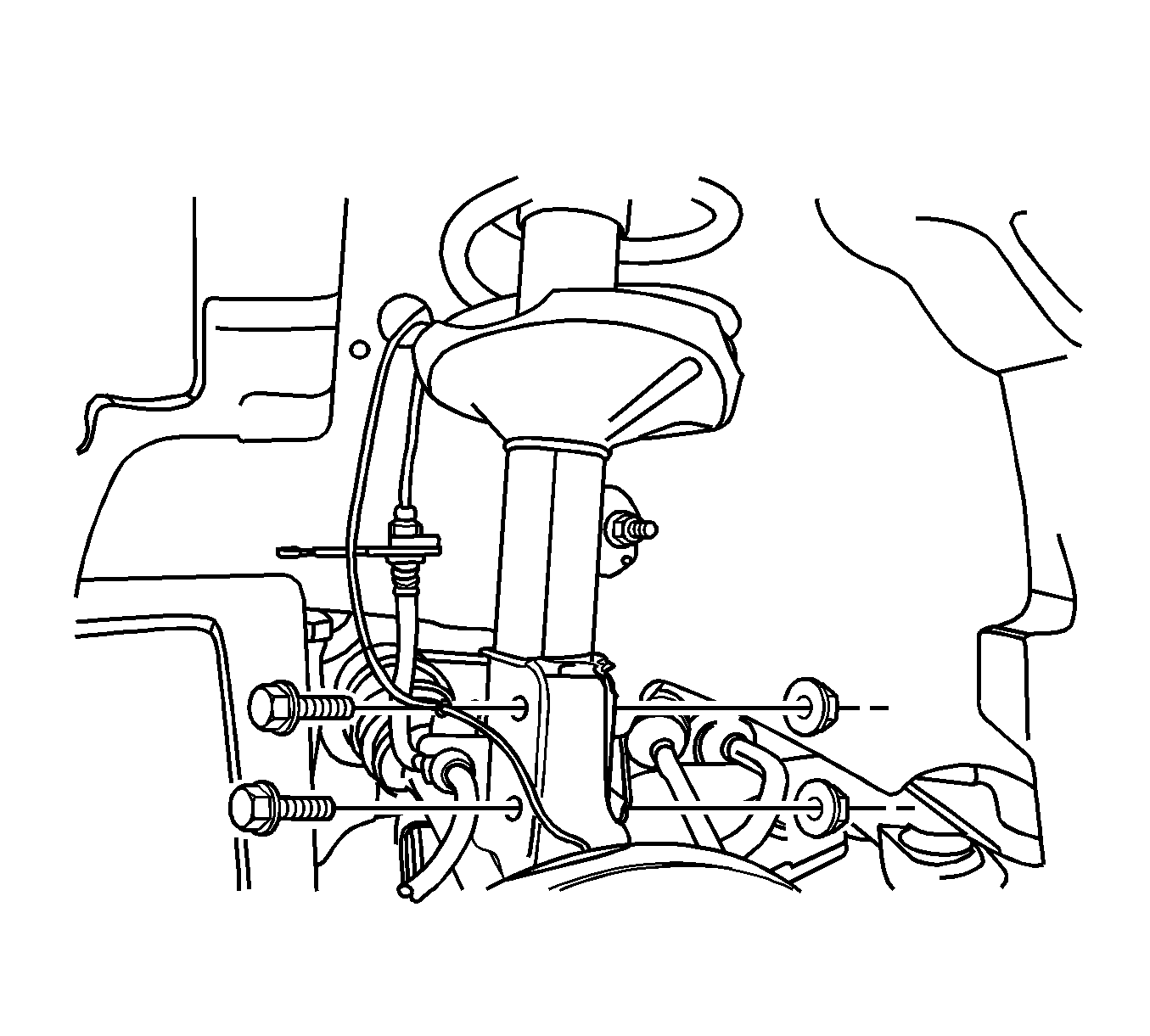
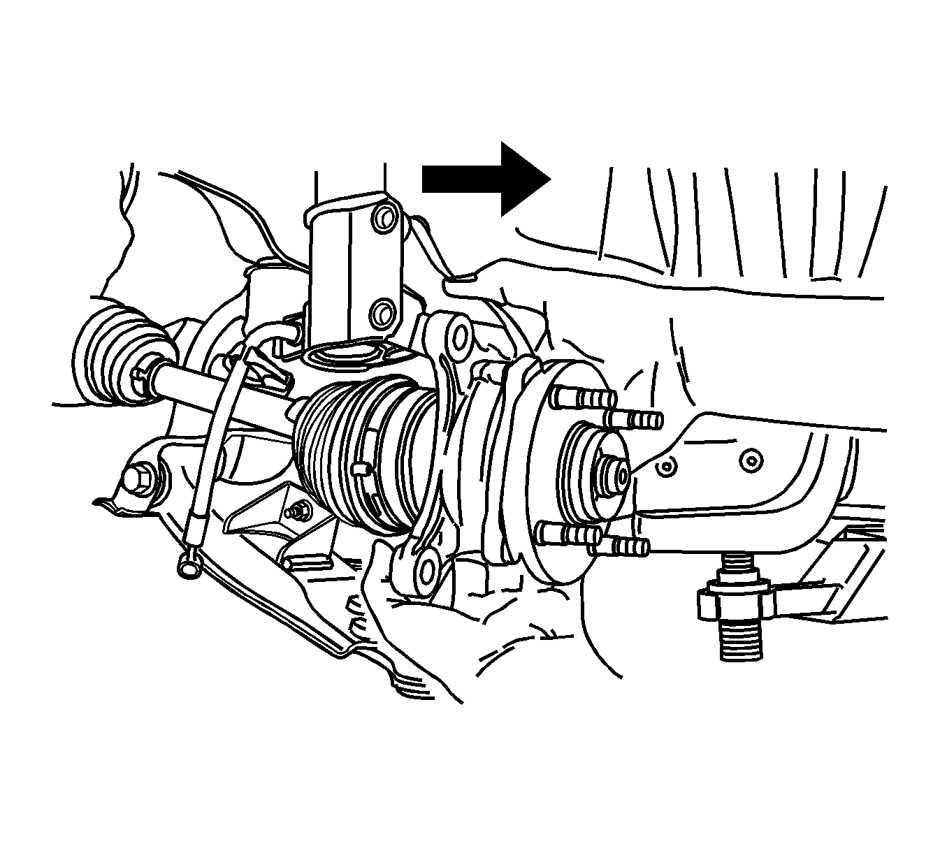
Caution: Do not overextend the wheel drive shaft. Allowing the inboard joint to overextend can cause separation of the internal components and lead to joint failure.
Installation Procedure
- Install the knuckle assembly onto the vehicle.
- Install the steering knuckle-to-strut assembly nuts and tighten to 120 N·m (89 lb ft).
- Connect the drive axle to the front wheel hub.
- Connect the ball joint to the knuckle assembly.
- Install the ball joint pinch bolt nut and tighten to 60 N·m (44 lb ft).
- Connect the ABS speed sensor electrical connection.
- Connect the outer tie rod to the knuckle assembly. Refer to Steering Linkage Outer Tie Rod Replacement.
- Install the brake caliper onto the rotor. Refer to Front Brake Caliper Replacement.
- Install the caulking nut onto the axle shaft and tighten to 150 N·m (111 lb ft). Loosen the nut, then tighten it to 275 N·m (203 lb ft).
- Install the wheel. Refer to Tire and Wheel Removal and Installation.
- Lower the vehicle.

Caution: Refer to Fastener Caution in the Preface section.


