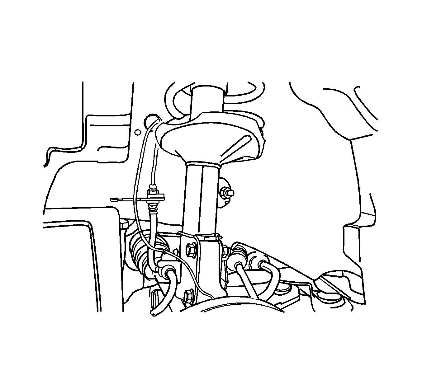
For 1990-2009 cars only
Removal Procedure
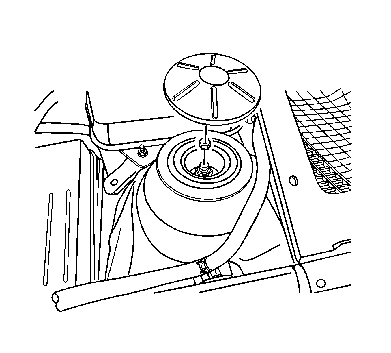
- Remove the strut upper cap and nut.
- Raise and suitably support the vehicle. Refer to Lifting and Jacking the Vehicle.
- Remove the wheel. Refer to Tire and Wheel Removal and Installation.
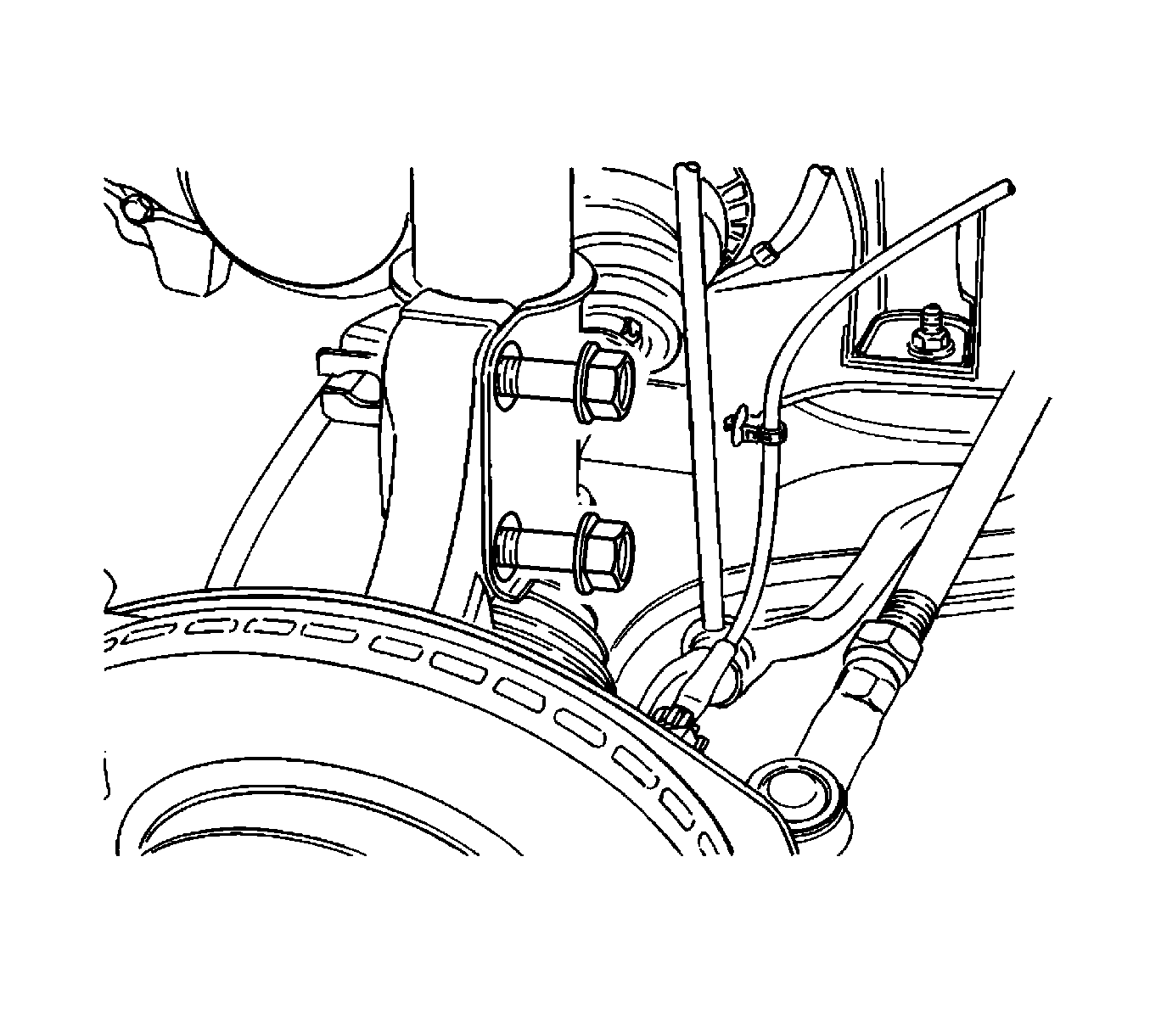
- On vehicles equipped with an antilock braking system (ABS), disconnect the ABS sensor line from the strut assembly.
- Remove the brake line from the securing bracket on the strut assembly.
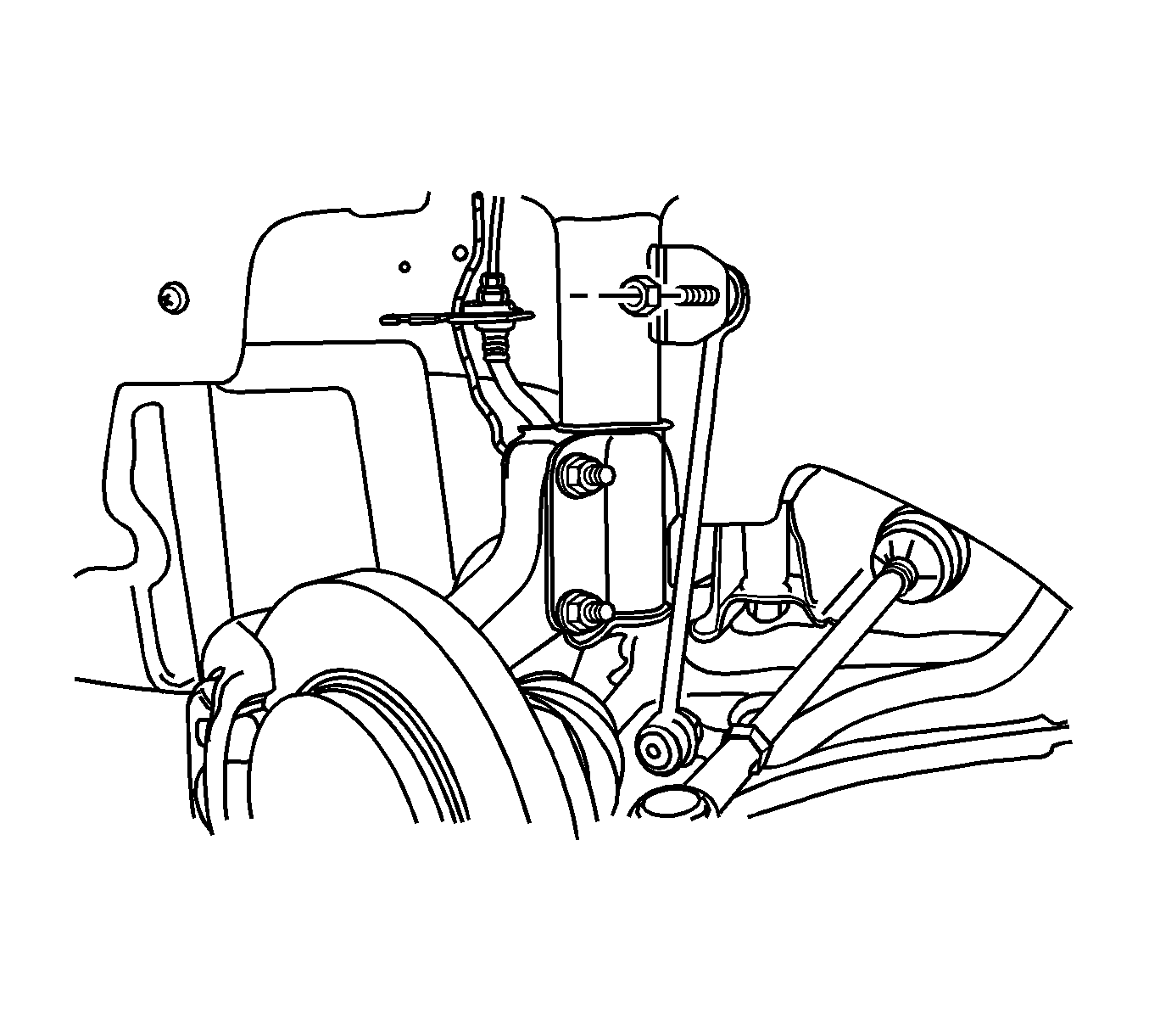
- Disconnect the stabilizer shaft link by removing the stabilizer link-to-strut assembly nut.
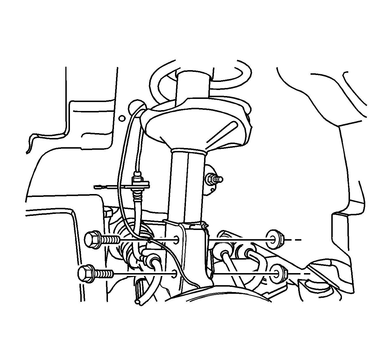
- Disconnect the steering knuckle by removing the steering knuckle-to-strut assembly nuts and bolts.
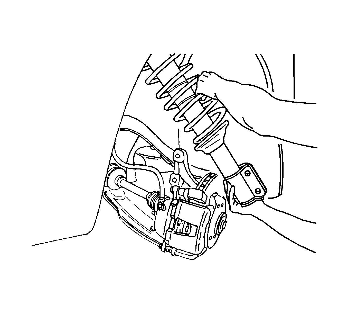
- Remove the strut assembly.
Installation Procedure
- Install the strut assembly.
- Connect the strut assembly to the steering knuckle by installing the steering knuckle-to-strut assembly nuts and bolts and tighten to 120 N·m (89 lb ft).
- Connect the stabilizer shaft link to the strut assembly by attaching the stabilizer link-to-strut assembly nut and tighten to 47 N·m (35 lb ft).
- Install the brake line to the securing bracket on the strut assembly.
- On vehicles equipped with the ABS, connect the ABS sensor line to the strut assembly.
- Install the wheel. Refer to Tire and Wheel Removal and Installation.
- Lower the vehicle.
- Install the nuts securing the strut assembly to the body of the vehicle and tighten to 65 N·m (48 lb ft).

Caution: Refer to Fastener Caution in the Preface section.
