GM Service Manual Online
For 1990-2009 cars only

ABS Description and Operation SWBLHD

Definition of Longitudinal Wheel Slip

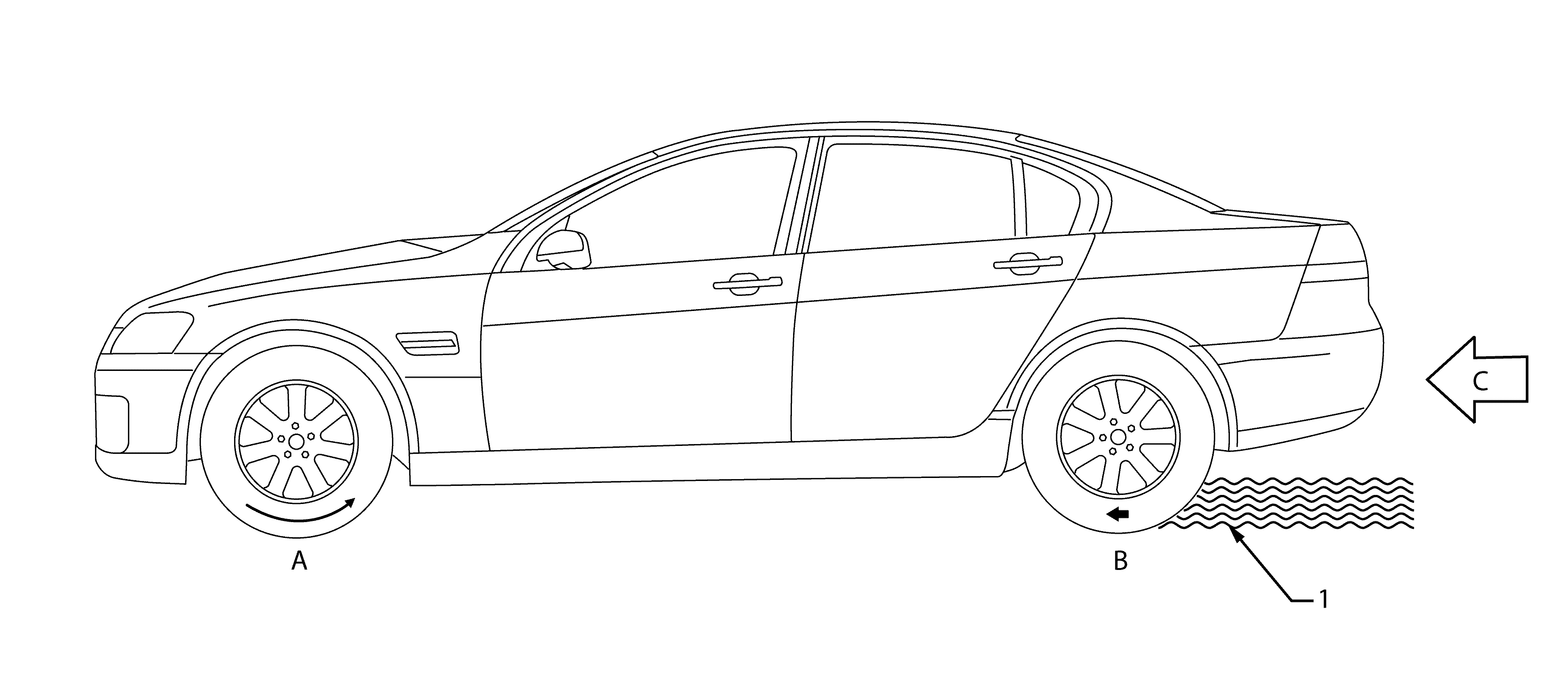
Longitudinal wheel slip is a loss of adhesion between the tyres and the road surface. This occurs when the vehicle is moving in a straight ahead direction and the braking or acceleration forces applied to a tyre exceeds the amount of adhesion available to that tyre.


Object Number: 1943581  Size: SF
    • At 0 percent slip, the front tyre rolls freely (A).
    • At 100 percent slip, the rear wheel locks-up (B) as the weight of the vehicle pushes the non-rotating tyre along the road surface (C). When the wheels are locked-up, the vehicle's kinetic energy (forward motion) is converted into thermal energy (heat) between the tyre and the road surface (1). This will result in an unstable and inefficient braking due to the effect of the following factors:
      • Asphalt, cement, gravel or dirt road surfaces provide different degree of tyre adhesion.
      • Oil puddles, ice spots or other contaminants that cause a sudden change in the road surface condition.
      • Wet, dry, smooth, rough road surface conditions affect tyre adhesion.

When none of the wheels are locked during braking, the brakes work by converting kinetic energy (forward motion of the vehicle) into thermal energy (heat). The friction between the stationary brake pad and the rotating disc as it slides past the pad convert the motion of the wheel and tyre into heat. The brake disc is designed to work like a heat sink, and absorbs as much as 80% of the heat generated during stopping. The brake disc is cooled as it spins through the air on the way to the next stop. The friction surfaces between the brake pads and the brake disc are designed to provide a stable and controlled braking action. Therefore, a vehicle that is braked without locking the wheel will stop in a shorter distance while maintaining directional stability and steering capability. Maximum braking efficiency is achieved when a wheel lock slip is prevented.

Definition of Lateral Wheel Slip

Lateral wheel slip is the loss of adhesion between the tyres and the road surface, which occurs when the vehicle is cornering or when too much engine torque is applied to the vehicle and the following forces applied to the tyres exceeds the amount of adhesion available to that tyre:

    • Cornering forces.
    • Acceleration force.
    • Braking force.

In addition, steering control depends upon tyre adhesion. A locked wheel in a 100 percent slip condition delivers poor braking and directional control.

The front tyre direction (A) has minimal steering effect while the vehicle skids in direction (B). The tyres must regain their adhesion before steering control is restored to the vehicle.


Object Number: 1943583  Size: SH

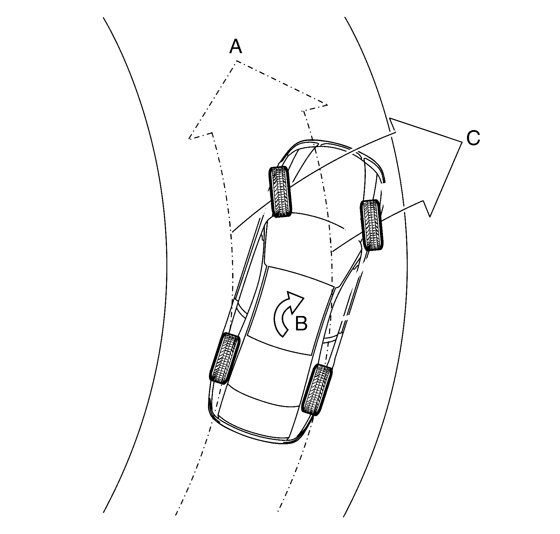
Definition of Understeer

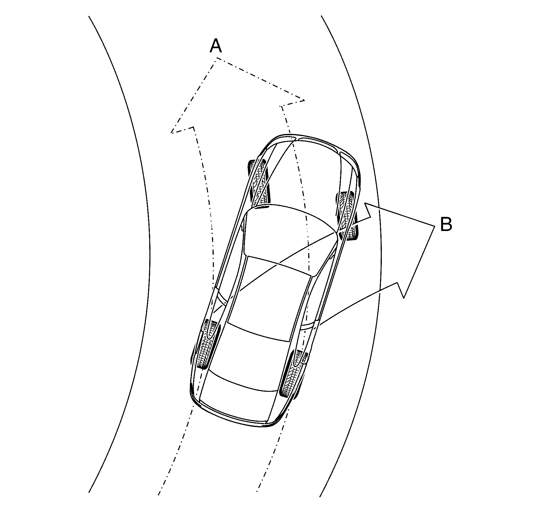
When the vehicle is cornering (A) at high speed or when the vehicle encounters a slippery road surface, the vehicle understeers when the cornering, braking or acceleration forces applied to the tyres exceeds the adhesion available between the tyres and the road surface.


Object Number: 1943584  Size: SH

Under this condition, the vehicle spins (B) with the front of the vehicle sliding in direction (C).

Definition of Oversteer

When the vehicle is cornering (A) at high speed or when the vehicle encounters a slippery road surface, the vehicle oversteers when the cornering, braking or acceleration forces applied to the tyres exceeds the adhesion available between the tyres and the road surface.


Object Number: 1943586  Size: SH

Under this condition, the vehicle spins (B) with the rear of the vehicle sliding in direction (C).

Electronic Brake Control Module


Object Number: 1943611  Size: SH

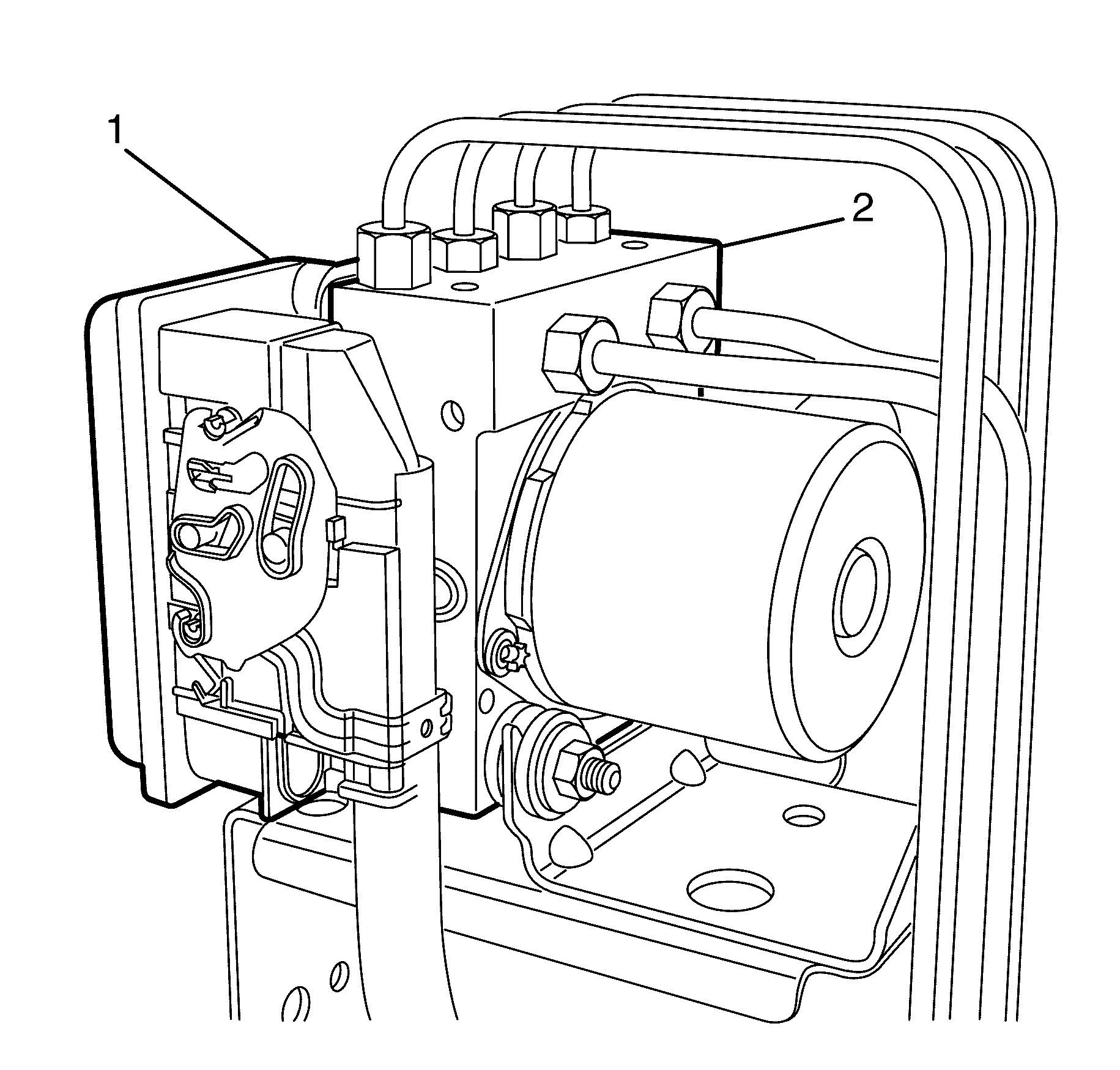
The Electronic Brake Control Module (EBCM) (1) is the control centre of the antilock braking system-traction control system with electronic stability program (ABS-TCS/ESP). It is integrated with the Brake Modulator Assembly (2) to form one assembly.

Electronic Brake Control Module Inputs

The EBCM constantly monitors and evaluates input signals from the following:

    • Wheel speed sensors.
    • Yaw-rate sensors.
    • Steering angle sensor.
    • Stop lamp switch.
    • Ignition on input.
    • Battery voltage.
    • Serial data communication circuit.

Electronic Brake Control Module Outputs

Based on the inputs received, the EBCM sends output signals to the following:

    • Instrument cluster multi-function display (MFD).
    • Diagnostic link connector.
    • Hydraulic modulator solenoid valves.
    • Hydraulic modulator pump motor.
    • Serial data communication circuit.

Electronic Brake Control Module Self-test Initialisation Sequence

When the ignition is switched on, the EBCM constantly performs a self-test that detects and isolates ABS-TCS/ESP faults. In addition, the EBCM performs on Self-test Initialisation Sequence for each ignition cycle. This Initialisation Sequence commences when the vehicle reaches approximately 15 km/h.

Important: The Initialisation Sequence may be heard and felt while it is taking place, which is considered part of the normal system operation.

During the Initialisation Sequence, the EBCM sends a control signal to the hydraulic modulator to cycle each of the solenoid valves as well as operate the pump motor to check for correct component operation. If the pump or any solenoid valves fail to operate, the EBCM sets a diagnostic trouble code (DTC).

When the vehicle speed exceeds 15 km/h, the EBCM continuously monitors the ABS-TCS/ESP by comparing the logical sequence of input and output signals with the normal operating parameters stored in the EBCM. If any of the input or output signals are outside the normal operating parameters, the EBCM sets the DTC.
Brake Pressure Modulator Valve


Object Number: 1943589  Size: SH
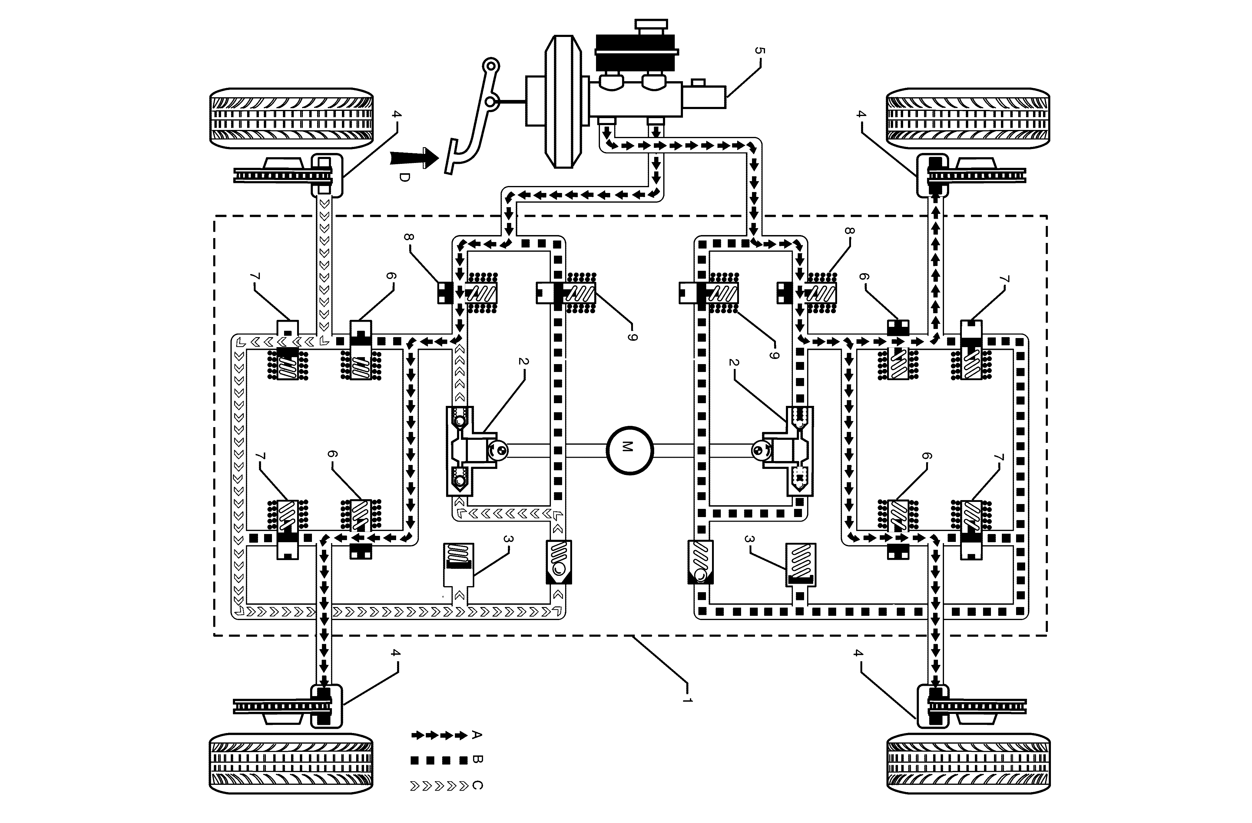
(1)Brake pressure modulator valve
(2)Return Pump
(3)Accumulator
(4)Brake Caliper
(5)Brake Master Cylinder
(6)Inlet Valves
(7)Outlet Valves
(8)Isolating Solenoid Valve
(9)Priming Solenoid Valve
(a)Normal (conventional) brake fluid pressure
(b)Stopped brake fluid pressure flow (solenoid valve closed)
(c)Pump generated brake fluid pressure flow
(d)Brake pedal applied
(m)Motor

Important: The illustration shows the brake pressure modulator valve components while in ABS pressure reducing phase. Refer to this illustration for the following hydraulic components.

The brake pressure modulator valve (BPMV) assembly (1) modulates the brake fluid pressure (A) based on the control signal sent by the electronic brake control module (EBCM).

To allow individual control of each wheel brake fluid circuit, a four-channel circuit configuration with a front/rear split is used. Each of the brake fluid circuits are hydraulically isolated, which enables continued braking ability if a leak develops in any of the brake fluid circuits. The BPMV components consist of the following:

    • Two return pumps (2) - Each pump draws excess brake fluid from the accumulators (3) and brake calipers (4) allowing the hydraulic modulator to return brake fluid to the brake master cylinder (5) against brake fluid pressure (C) during the ABS-TCS/ESP pressure reducing phase. In addition, the return pump applies pressure to the brake calipers during the ABS brake intervention phase.
    • One electric motor (M) - The electric motor drives the return pump.
    • Two accumulators - The accumulators store the excess brake fluid during the ABS-TCS/ESP pressure reducing phase that enables the hydraulic modulator to apply instant pressure reduction.
    • Four inlet valves (6) - At rest position, each inlet valve allows brake fluid pressure to be applied to the brake callipers. When active, each inlet valve isolates a brake calliper from the brake master cylinder.
    • Four outlet valves (7) - At rest position, each outlet valve isolates a brake calliper from the accumulator and return pump. When active, each outlet valve directs excess brake fluid to the accumulator and return pump that allows pressure reduction.
    • Two isolating solenoid valves (8) - The isolating solenoid valves isolate the rear brake fluid circuits from the brake master cylinder which prevents the return of the brake fluid to the brake master cylinder during TCS operation.
    • Two rear priming valves (9) - Allow brake fluid to be drawn from the brake master cylinder into the hydraulic pump during TCS operation.

Wheel Speed Sensor

Active wheel speed sensors are fitted to this vehicle. Active wheel speed sensors are direction sensitive.

The wheel speed sensor receives a 12-volt power supply voltage from the electronic brake control module (EBCM). The wheel speed sensor contains an integrated circuit containing a magneto-resistive bridge. Wheel rotation changes the positioning of the tone wheel and the wheel speed sensor's magnetic field and varies the magneto-resistive bridge resistance. The wheel speed sensor's integrated circuit modifies and amplifies the varying resistance into a direct current (DC) square wave signal. Therefore as the wheel spins, the wheel speed sensor changes the voltage and current level output signal to the EBCM. The wheel speed sensor always has a current flow on the output signal circuit to complete the wheel speed sensor's ground path and for EBCM diagnostics. The EBCM uses the frequency of the square wave signal to calculate the wheel speed.

Brake Pedal Position Sensor

The brake pedal position sensor (1) is a normally open switch that closes when the brake pedal is depressed.


Object Number: 1943576  Size: SH

The electronic brake control module (EBCM) uses the stop lamp switch signal voltage to determine when the brake pedal is depressed.

Electronic Stability Program (ESP) Switch


Object Number: 1943579  Size: SH

The ESP switch incorporates traction control (TCS) which is part of a multi function centre console switch assembly and is located in the console as shown above.

The ESP switch is a momentary contact switch that sends a ground output signal to the body control module (BCM).

The BCM sends a signal to the EBCM via the serial data bus to perform the following functions:

    • Pressing the ESP switch once deactivates both TCS and ESP for the duration of that ignition cycle. ABS will still function normally when the TCS and ESP is deactivated.
    • Pressing the ESP switch again when the TCS and ESP is deactivated, activates the TCS and ESP.
    • Pressing the ESP switch for more than 60 seconds will be interpreted as a short circuit. Consequently, a DTC will be logged and the TCS and ESP will be deactivated for the duration of that ignition cycle.

If there are no current TCS/ESP DTC's logged, the ESP activates at the next ignition cycle.

Yaw Rate Sensor

The yaw-rate sensor assembly (1) comprises of a yaw-rate sensor and a lateral acceleration sensor.


Object Number: 1943594  Size: SH
    • The yaw-rate sensor produces a signal output voltage that corresponds to a vehicle rotation around its vertical axis.
    • The lateral acceleration sensor produces a signal output voltage that corresponds to a vehicle lateral acceleration.

The EBCM uses the output signal voltage of the yaw-rate sensor and the acceleration sensor in conjunction with the wheel speed sensor signal output voltage and serial data output signal of the steering angle sensor, to support the calculation of actual vehicle behavior as compared to the driver intended direction.

Lateral Acceleration Sensor


Object Number: 1943598  Size: SH

Important: This illustration represents the lateral acceleration sensor in symbolic form, which aims to show the operation of the acceleration sensor in a simplified manner.

The lateral acceleration sensor consists of the following components:

    • Differential capacitors connected to the fixed side plates (1).
    • Mass plate (2) suspended by springs (3) about its centre of mass, which moves in response to vehicle lateral acceleration.

When the vehicle is stationary (View A), the distance between the mass plate and the 2 side plates are equal. Therefore, the capacitance between the 2 capacitors is the same and the acceleration sensor signal voltage is zero.

As the vehicle accelerates (View B), the side plates move with the vehicle (C) while the mass plate, which is suspended by springs tends to move in the opposite direction. Therefore, the distance between the side plates and the mass plates changes in proportion to the level of acceleration.

This changes the capacitance between the 2 capacitors causing the acceleration sensor to produce a signal voltage with an amplitude proportional to the movement of the mass plates.

Yaw Rate Sensor


Object Number: 1943600  Size: SH

Important: This illustration represent the yaw rate sensor in symbolic form, which shows the operation of the yaw rate sensor in a simplified manner.

The yaw-rate sensor consists of the following components:

    • Two oscillating plates (1) suspended by springs (2) around its center of mass.
    • An acceleration sensor (3) incorporated within the oscillating plates.
    • Permanent magnets, which project magnetic field to the oscillating plates.

While in the presence of a magnetic field, electric current is applied to the oscillating plates, which causes the plates to move at a constant amplitude (W).

When the vehicle is driving in a straight-ahead direction and there are not lateral forces applied to the acceleration sensors, the distance between the mass plates (4) and the side plates of the acceleration sensors are equal (5). Therefore, the capacitance between the capacitors are the same and the acceleration sensor signal voltage is zero.

When the vehicle rotates around its vertical axis, the following situation occurs.


Object Number: 1943592  Size: SH
    • With the exception of the mass plates (1), the yaw-rate sensor (2), which is firmly attached to the vehicle rotates with the vehicle (Z).
    • The mass plates, which are suspended by springs (3) and moves along with the oscillating plates (4), tend to float in its current position while the fixed side plates (5) rotate with the vehicle. Therefore, the distance between the fixed side plates and the mass plates of the acceleration sensor changes in proportion to the level of vehicle rotation around its vertical axis.
    • This changes the capacitance between the capacitors causing the acceleration sensor to produce a signal voltage with an amplitude proportional to the movement of the mass plates.

The evaluation circuit of the yaw-rate sensor compares and evaluates the output signal of both acceleration sensors to calculate the level of vehicle rotation around its vertical axis.

Steering Angle Sensor

The steering angle sensor provides a signal output that represents the steering wheel degree of rotation. The EBCM uses this information to calculate the driver intended driving direction. The steering angle sensor contains:


Object Number: 1943602  Size: SH
    • Gear Wheel (1).
    • Measuring Gears (2).
    • Measuring Gear Magnets (3).
    • Evaluation Circuit (4).
    • Anisotropic Magneto Resistive (AMR) Integrated Circuit (IC) (5).

The anisotropic magneto resistive integrated circuit (AMRIC) (1) comprises of eight AMR elements (2) which are configured to form two Wheatstone bridges (3).


Object Number: 1943614  Size: SH

One of the Wheatstone bridges (4) is 45 degrees offset from the other to enable the AMR IC to produce sine (5) and cosine (6) output signal.

The AMR elements change resistance that corresponds to the changes in the angle of magnetic field projected to the AMR IC, regardless of the polarity of the magnetic field.

The evaluation circuit of the steering angle sensor evaluated and combines the output signal of the AMR IC to produce two identical linear output (A) that represents the 360 degrees angular rotation of the magnetic field.

The omni polarity of the AMR elements limits the signal output range of a single AMR IC from 0-180 degrees.

Steering Angle Sensor Layout

To increase the output signal range of the steering angle sensor, and enable it to produce an output signal that can represent the ±760 degrees of steering wheel rotation, two AMR ICs are fitted to the steering angle sensor.


Object Number: 1943605  Size: SH

The magnets (1) that project magnetic fields to the AMR ICs are mounted on the primary measuring gear (2) and secondary measuring gear (3).

The secondary gear has two less teeth when compared against the primary measuring gear. This causes the measuring gears to rotate at a different ratio.

Steering Angle Sensor Operation

The angular orientation of the magnetic fields produced by the measuring gear magnets (1) corresponds to the degree of steering wheel angular position.


Object Number: 1943603  Size: SH

This magnetic field changes the resistance value of the AMR elements, which enable the AMR ICs (2) to produce a pair of signal outputs (3).

The difference in the rotational ratio between the measuring gears causes the signal output of the second AMR IC (A) to be shorter in range when compared against the signal output of the first AMR IC (B).

The evaluation circuit (4) compares and evaluates this difference, and the rate of change between the output signals of the AMR ICs, at parallel points (5) to calculate that precise steering wheel angular position.

Antilock Brake System Operation

The antilock braking system (ABS) prevents wheel lock-up during hard or emergency braking by modulating the brake fluid pressure applied to the appropriate wheels. The ABS cycles through the following phases when the electronic brake control module (EBCM) detects the beginning of the wheel lock-up:

    • Maintaining pressure.
    • Reducing pressure.
    • Increasing pressure.

Important: The following are conditions that may be experienced when the ABS is active and are considered normal:

   • During ABS controlled braking, the braking pressure of the affected wheel is automatically adjusted to prevent wheel lock-up, regardless of pressure applied to the brake pedal.
   • A series of rapid pulsations are felt through the brake pedal. These pulsations occur as solenoid valves within the hydraulic modulator changes position to modulate the brake hydraulic pressure.
   • A ticking or popping noise in the hydraulic modulator occurs as the hydraulic modulator solenoid valves cycle rapidly to modulate the hydraulic brake pressure.
   • Intermittent chirping noises may be heard as the tyres approach slipping on dry pavement.
   • Electric motor and pump noise and rapid brake pedal pulsation caused by the operation of the hydraulic modulator pump during the ABS reducing or increasing pressure phase or the EBCM self-test.

ABS Phase - Maintaining Pressure

The EBCM closes the inlet valve and keeps the outlet valve closed in order to isolate the system when wheel slip occurs. This maintains the pressure steady on the brake so that the hydraulic pressure does not increase or decrease.

ABS Phase - Reducing Pressure

The EBCM decreases the pressure to individual wheels during a deceleration when wheel slip occurs. The inlet valve is closed and the outlet valve is opened. The excess fluid is stored in the accumulator until the return pump can return the fluid to the master cylinder.

ABS Phase - Increasing Pressure

The EBCM increases the pressure to individual wheels during a deceleration in order to reduce the speed of the wheel. The inlet valve is opened and the outlet valve is closed. The increased pressure is delivered from the master cylinder.

Electronic Brake-Force Distribution System

The electronic brake-force distribution (EBD) system is part of the ABS software programmed into the electronic brake control module (EBCM). It is designed to replace the rear brake proportioning valve in reducing rear wheel slip during moderate braking.

The EBD system utilises the existing ABS active controls to regulate the vehicle's rear brake fluid pressure. This enables the EBD system to provide dynamic front to rear brake proportioning under various vehicle loads, driving manoeuvres, or road conditions.

In some situations, when the EBD system is activated, a brake pedal height drop of approximately 10 mm will be experienced when the driver varies the brake pedal pressure while performing brake stops. This is caused by the hydraulic modulator performing an adjustment on the rear brake fluid pressure and is considered normal.

EBD System Keep Alive Function

The EBD system plays an important role in vehicle stability during braking. For this reason, the EBD system has a Keep Alive Function integrated in its software. When the EBCM detects a fault in the ABS, depending on the type of fault, certain parts of the system are kept alive. This allows the EBD system to apply some rear wheel brake proportioning even under certain ABS faults.

Traction Control System

The traction control system (TCS) utilises the active braking controls in the ABS and the engine torque reduction function of the engine management system to prevent longitudinal wheel spin during vehicle acceleration.

When drive wheel slip is noted while the brake is not applied, the EBCM will enter traction control mode.

First, the EBCM requests the ECM to reduce the amount of torque to the drive wheels via the requested torque signal circuit. The ECM reduces torque to the drive wheels by retarding spark timing and turning off fuel injectors. The ECM reports the amount torque delivered to the drive wheels via the delivered torque signal circuit.

If the engine torque reduction does not abolish drive wheel slip, the EBCM will actively apply the drive wheel brakes. During traction control braking, hydraulic pressure in each drive wheel circuit is controlled to prevent the drive wheels from slipping. The master cylinder isolation valve closes in order to isolate the master cylinder from the rest of the hydraulic system. The prime valve then opens in order to allow the pump to accumulate brake fluid in order to build hydraulic pressure for braking. The drive wheel inlet and outlet solenoid valves then open and close in order to perform the following functions:

    • Pressure increase.
    • Pressure hold.
    • Pressure decrease.

If at any time during TCS mode the brakes are manually applied, the brake switch sends a signal to the EBCM to exit the TCS brake intervention mode and allow for manual braking.

Electronic Stability Program

The electronic stability program (ESP) is designed to provide optimum vehicle stability and steering control during high speed cornering or when driving on a slippery road surface.

Yaw rate is the rate of rotation about the vehicle's vertical axis. The VSES is activated when the EBCM determines that the desired yaw rate does not match the actual yaw rate as measured by the yaw rate sensor.

The desired yaw rate is calculated from the following parameters:

    • The position of the steering wheel.
    • The speed of the vehicle.
    • The lateral, or sideways acceleration of the vehicle.

The difference between the desired yaw rate and the actual yaw rate is the yaw rate error, which is a measurement of oversteer or understeer. If the yaw rate error becomes too large, the EBCM attempts to correct the vehicle's yaw motion by applying differential braking to the appropriate wheel. The amount of differential braking applied to the left or right front wheel is based on both the yaw rate error and side slip rate error.

The VSES activations generally occur during aggressive driving, in turns or on bumpy roads without much use of the accelerator pedal. When braking during VSES activation, the pedal pulsations feel different than the ABS pedal pulsations. The brake pedal pulsates at a higher frequency during VSES activation.

The ESP incorporates the following components:

    • Steering angle sensor to determine driver steering input, which the EBCM uses to support the calculation of intended vehicle direction.
    • Yaw rate sensor to measure vehicle rotation around its vertical axis, which the EBCM uses to support the calculation of actual vehicle behaviour.
    • Active braking and engine torque reduction functionality of the TCS to prevent wheel spin.

When the ESP detects a lateral wheel slip or when the calculated vehicle direction deviates from the actual vehicle direction, the ESP utilises the engine torque reduction functionality and the active braking controls in the ABS-TCS to stabilise and steer the vehicle to the correct direction.

ESP Engine Torque Reduction

The ESP monitors the wheel speed sensor, yaw-rate sensor and the steering angle sensor to determine lateral wheel slip. When the ESP detects a lateral wheel slip, the ESP initially utilises the torque reduction functionality of the TCS and sends a serial data communication signal to the engine control module (ECM) requesting engine torque reduction. In addition, if the ESP still detects a lateral wheel slip, the ESP applies active brake intervention.

ESP Brake Intervention

The ESP applies active brake intervention when the EBCM receives the following input signals and determines the vehicle is beginning to understeer.


Object Number: 1943606  Size: SH
    • The steering angle sensor sends a signal to the EBCM the driver intends to steer in direction (A).
    • The yaw rate sensor detects the vehicle begins to spin (B) with the front of the vehicle beginning to slide in direction (C).

The ESP uses the existing active braking control in the ABS-TCS to apply a calculated braking force to one or both inner wheels (1) of the vehicle to stabilise and steer the vehicle to the intended direction.


Object Number: 1943607  Size: SH

Important: Applying brake-force to the inner wheel (1) slows down the inner side of the vehicle, which induces the vehicle to rotate on its vertical axis (A).

The EBCM monitors and compares signals from the yaw-rate sensor, steering angle sensor and each wheel speed sensor to determine wheel slip. If the EBCM detects the beginning of a vehicle understeer condition, the EBCM sends the following signal to the hydraulic modulator to:

    • Close the front and rear isolating valves.
    • Open the front and rear prime valves.
    • Close the front right and rear right inlet valves.
    • Operate the hydraulic modulator pump.

This results in the following actions:

    • The rear isolation valve is closed to isolate the rear brake fluid circuits from the master cylinder and prevent the brake fluid returning to the brake master cylinder when the hydraulic pump builds-up the brake fluid pressure.
    • The front right and rear right inlet valves are closed to isolate the right wheel hydraulic circuits, allowing the hydraulic modulator to supply brake fluid pressure only to the left wheels.
    • The rear priming valve is open to allow fluid to be drawn from the master cylinder into the hydraulic pump.
    • The hydraulic pump applies appropriate brake fluid pressure to the left brake callipers to steer the vehicle to the intended direction.
    • The hydraulic modulator modulates the front left and rear left inlet valves and outlet valves to assist in obtaining maximum road surface traction in the same manner as in the TCS Mode.

       Important: If at any time during the ESP Mode the brakes are manually applied, the brake switch sends a signal to the EBCM to exit the ESP Brake Intervention Mode and allow normal braking.

The ESP applies active brake intervention when the EBCM receives the following input signals and determines the vehicle is beginning to oversteer.


Object Number: 1943608  Size: SH
    • The steering angle sensor sends a signal to the EBCM the driver intends to steer in direction (A).
    • The yaw-rate sensor detects the vehicle begins to spin (B) with the rear of the vehicle beginning to slide in direction (C).

The ESP uses the existing active braking control in the ABS-TCS to apply a calculated braking force to one or both outer wheels (1) of the vehicle to stabilise and steer the vehicle to the intended direction.


Object Number: 1943610  Size: SH

Applying brake-force to the outer wheel (1) slows down the outer side of the vehicle, which induces the inner wheel to rotate on its vertical axis (A).

The EBCM monitors and compares signals from the yaw-rate sensor, steering angle sensor and each wheel speed sensor to determine wheel slip. If the EBCM detects the beginning of a vehicle oversteer condition, the EBCM sends the following signal to the hydraulic modulator to:

    • Close the front and rear isolating valves.
    • Open the front and rear prime valves.
    • Close the front right and rear right inlet valves.
    • Operate the hydraulic modulator pump.

This results in the following actions:

    • The rear isolation valve is closed to isolate the rear brake fluid circuits from the master cylinder and prevent the brake fluid returning to the brake master cylinder when the hydraulic pump builds-up the brake fluid pressure.
    • The front left and rear left inlet valves are closed to isolate the right wheel hydraulic circuits, allowing the hydraulic modulator to supply brake fluid pressure only to the left wheels.
    • The rear priming valves are open to allow fluid to be drawn from the master cylinder to the hydraulic pump.
    • The hydraulic pump applies appropriate brake fluid pressure to the left brake callipers to stern the vehicle to the intended direction.
    • The hydraulic modulator modulates the front right and rear right inlet valves and outlet valves to assist in obtaining maximum road surface traction in the same manner as in the TCS Mode.

       Important: If at any time during the ESP Mode the brakes are manually applied, the brake switch sends a signal to the EBCM to exit the ESP Brake Intervention Mode and allow normal braking.

ABS Description and Operation SWBRHD

Definition of Longitudinal Wheel Slip

Longitudinal wheel slip is a loss of adhesion between the tyres and the road surface. This occurs when the vehicle is moving in a straight ahead direction and the braking or acceleration forces applied to a tyre exceeds the amount of adhesion available to that tyre.


Object Number: 1943581  Size: SF
    • At 0 percent slip, the front tyre rolls freely (A).
    • At 100 percent slip, the rear wheel locks-up (B) as the weight of the vehicle pushes the non-rotating tyre along the road surface (C). When the wheels are locked-up, the vehicle's kinetic energy (forward motion) is converted into thermal energy (heat) between the tyre and the road surface (1). This will result in an unstable and inefficient braking due to the effect of the following factors:
      • Asphalt, cement, gravel or dirt road surfaces provide different degree of tyre adhesion.
      • Oil puddles, ice spots or other contaminants that cause a sudden change in the road surface condition.
      • Wet, dry, smooth, rough road surface conditions affect tyre adhesion.

When none of the wheels are locked during braking, the brakes work by converting kinetic energy (forward motion of the vehicle) into thermal energy (heat). The friction between the stationary brake pad and the rotating disc as it slides past the pad convert the motion of the wheel and tyre into heat. The brake disc is designed to work like a heat sink, and absorbs as much as 80% of the heat generated during stopping. The brake disc is cooled as it spins through the air on the way to the next stop. The friction surfaces between the brake pads and the brake disc are designed to provide a stable and controlled braking action. Therefore, a vehicle that is braked without locking the wheel will stop in a shorter distance while maintaining directional stability and steering capability. Maximum braking efficiency is achieved when a wheel lock slip is prevented.

Definition of Lateral Wheel Slip

Lateral wheel slip is the loss of adhesion between the tyres and the road surface, which occurs when the vehicle is cornering or when too much engine torque is applied to the vehicle and the following forces applied to the tyres exceeds the amount of adhesion available to that tyre:

    • Cornering forces.
    • Acceleration force.
    • Braking force.

In addition, steering control depends upon tyre adhesion. A locked wheel in a 100 percent slip condition delivers poor braking and directional control.

The front tyre direction (A) has minimal steering effect while the vehicle skids in direction (B). The tyres must regain their adhesion before steering control is restored to the vehicle.


Object Number: 1943583  Size: SH

Definition of Understeer

When the vehicle is cornering (A) at high speed or when the vehicle encounters a slippery road surface, the vehicle understeers when the cornering, braking or acceleration forces applied to the tyres exceeds the adhesion available between the tyres and the road surface.


Object Number: 1943584  Size: SH

Under this condition, the vehicle spins (B) with the front of the vehicle sliding in direction (C).

Definition of Oversteer

When the vehicle is cornering (A) at high speed or when the vehicle encounters a slippery road surface, the vehicle oversteers when the cornering, braking or acceleration forces applied to the tyres exceeds the adhesion available between the tyres and the road surface.


Object Number: 1943586  Size: SH

Under this condition, the vehicle spins (B) with the rear of the vehicle sliding in direction (C).

Electronic Brake Control Module


Object Number: 1943611  Size: SH

The Electronic Brake Control Module (EBCM) (1) is the control centre of the antilock braking system-traction control system with electronic stability program (ABS-TCS/ESP). It is integrated with the Brake Modulator Assembly (2) to form one assembly.

Electronic Brake Control Module Inputs

The EBCM constantly monitors and evaluates input signals from the following:

    • Wheel speed sensors.
    • Yaw-rate sensors.
    • Steering angle sensor.
    • Stop lamp switch.
    • Ignition on input.
    • Battery voltage.
    • Serial data communication circuit.

Electronic Brake Control Module Outputs

Based on the inputs received, the EBCM sends output signals to the following:

    • Instrument cluster multi-function display (MFD).
    • Diagnostic link connector.
    • Hydraulic modulator solenoid valves.
    • Hydraulic modulator pump motor.
    • Serial data communication circuit.

Electronic Brake Control Module Self-test Initialisation Sequence

When the ignition is switched on, the EBCM constantly performs a self-test that detects and isolates ABS-TCS/ESP faults. In addition, the EBCM performs on Self-test Initialisation Sequence for each ignition cycle. This Initialisation Sequence commences when the vehicle reaches approximately 15 km/h.

Important: The Initialisation Sequence may be heard and felt while it is taking place, which is considered part of the normal system operation.

During the Initialisation Sequence, the EBCM sends a control signal to the hydraulic modulator to cycle each of the solenoid valves as well as operate the pump motor to check for correct component operation. If the pump or any solenoid valves fail to operate, the EBCM sets a diagnostic trouble code (DTC).

When the vehicle speed exceeds 15 km/h, the EBCM continuously monitors the ABS-TCS/ESP by comparing the logical sequence of input and output signals with the normal operating parameters stored in the EBCM. If any of the input or output signals are outside the normal operating parameters, the EBCM sets the DTC.
Brake Pressure Modulator Valve


Object Number: 1943589  Size: SH
(1)Brake pressure modulator valve
(2)Return Pump
(3)Accumulator
(4)Brake Caliper
(5)Brake Master Cylinder
(6)Inlet Valves
(7)Outlet Valves
(8)Isolating Solenoid Valve
(9)Priming Solenoid Valve
(a)Normal (conventional) brake fluid pressure
(b)Stopped brake fluid pressure flow (solenoid valve closed)
(c)Pump generated brake fluid pressure flow
(d)Brake pedal applied
(m)Motor

Important: The illustration shows the brake pressure modulator valve components while in ABS pressure reducing phase. Refer to this illustration for the following hydraulic components.

The brake pressure modulator valve (BPMV) assembly (1) modulates the brake fluid pressure (A) based on the control signal sent by the electronic brake control module (EBCM).

To allow individual control of each wheel brake fluid circuit, a four-channel circuit configuration with a front/rear split is used. Each of the brake fluid circuits are hydraulically isolated, which enables continued braking ability if a leak develops in any of the brake fluid circuits. The BPMV components consist of the following:

    • Two return pumps (2) - Each pump draws excess brake fluid from the accumulators (3) and brake calipers (4) allowing the hydraulic modulator to return brake fluid to the brake master cylinder (5) against brake fluid pressure (C) during the ABS-TCS/ESP pressure reducing phase. In addition, the return pump applies pressure to the brake calipers during the ABS brake intervention phase.
    • One electric motor (M) - The electric motor drives the return pump.
    • Two accumulators - The accumulators store the excess brake fluid during the ABS-TCS/ESP pressure reducing phase that enables the hydraulic modulator to apply instant pressure reduction.
    • Four inlet valves (6) - At rest position, each inlet valve allows brake fluid pressure to be applied to the brake callipers. When active, each inlet valve isolates a brake calliper from the brake master cylinder.
    • Four outlet valves (7) - At rest position, each outlet valve isolates a brake calliper from the accumulator and return pump. When active, each outlet valve directs excess brake fluid to the accumulator and return pump that allows pressure reduction.
    • Two isolating solenoid valves (8) - The isolating solenoid valves isolate the rear brake fluid circuits from the brake master cylinder which prevents the return of the brake fluid to the brake master cylinder during TCS operation.
    • Two rear priming valves (9) - Allow brake fluid to be drawn from the brake master cylinder into the hydraulic pump during TCS operation.

Wheel Speed Sensor

Active wheel speed sensors are fitted to this vehicle. Active wheel speed sensors are direction sensitive.

The wheel speed sensor receives a 12-volt power supply voltage from the electronic brake control module (EBCM). The wheel speed sensor contains an integrated circuit containing a magneto-resistive bridge. Wheel rotation changes the positioning of the tone wheel and the wheel speed sensor's magnetic field and varies the magneto-resistive bridge resistance. The wheel speed sensor's integrated circuit modifies and amplifies the varying resistance into a direct current (DC) square wave signal. Therefore as the wheel spins, the wheel speed sensor changes the voltage and current level output signal to the EBCM. The wheel speed sensor always has a current flow on the output signal circuit to complete the wheel speed sensor's ground path and for EBCM diagnostics. The EBCM uses the frequency of the square wave signal to calculate the wheel speed.

Brake Pedal Position Sensor

The brake pedal position sensor (1) is a normally open switch that closes when the brake pedal is depressed.


Object Number: 1943591  Size: SH

The electronic brake control module (EBCM) uses the stop lamp switch signal voltage to determine when the brake pedal is depressed.

Electronic Stability Program (ESP) Switch


Object Number: 1943613  Size: SH

The ESP switch incorporates traction control (TCS) which is part of a multi function centre console switch assembly and is located in the console as shown above.

The ESP switch is a momentary contact switch that sends a ground output signal to the body control module (BCM).

The BCM sends a signal to the EBCM via the serial data bus to perform the following functions:

    • Pressing the ESP switch once deactivates both TCS and ESP for the duration of that ignition cycle. ABS will still function normally when the TCS and ESP is deactivated.
    • Pressing the ESP switch again when the TCS and ESP is deactivated, activates the TCS and ESP.
    • Pressing the ESP switch for more than 60 seconds will be interpreted as a short circuit. Consequently, a DTC will be logged and the TCS and ESP will be deactivated for the duration of that ignition cycle.

If there are no current TCS/ESP DTC's logged, the ESP activates at the next ignition cycle.

Yaw Rate Sensor

The yaw-rate sensor assembly (1) comprises of a yaw-rate sensor and a lateral acceleration sensor.


Object Number: 1943594  Size: SH
    • The yaw-rate sensor produces a signal output voltage that corresponds to a vehicle rotation around its vertical axis.
    • The lateral acceleration sensor produces a signal output voltage that corresponds to a vehicle lateral acceleration.

The EBCM uses the output signal voltage of the yaw-rate sensor and the acceleration sensor in conjunction with the wheel speed sensor signal output voltage and serial data output signal of the steering angle sensor, to support the calculation of actual vehicle behavior as compared to the driver intended direction.

Lateral Acceleration Sensor


Object Number: 1943598  Size: SH

Important: This illustration represents the lateral acceleration sensor in symbolic form, which aims to show the operation of the acceleration sensor in a simplified manner.

The lateral acceleration sensor consists of the following components:

    • Differential capacitors connected to the fixed side plates (1).
    • Mass plate (2) suspended by springs (3) about its centre of mass, which moves in response to vehicle lateral acceleration.

When the vehicle is stationary (View A), the distance between the mass plate and the 2 side plates are equal. Therefore, the capacitance between the 2 capacitors is the same and the acceleration sensor signal voltage is zero.

As the vehicle accelerates (View B), the side plates move with the vehicle (C) while the mass plate, which is suspended by springs tends to move in the opposite direction. Therefore, the distance between the side plates and the mass plates changes in proportion to the level of acceleration.

This changes the capacitance between the 2 capacitors causing the acceleration sensor to produce a signal voltage with an amplitude proportional to the movement of the mass plates.

Yaw Rate Sensor


Object Number: 1943600  Size: SH

Important: This illustration represent the yaw rate sensor in symbolic form, which shows the operation of the yaw rate sensor in a simplified manner.

The yaw-rate sensor consists of the following components:

    • Two oscillating plates (1) suspended by springs (2) around its center of mass.
    • An acceleration sensor (3) incorporated within the oscillating plates.
    • Permanent magnets, which project magnetic field to the oscillating plates.

While in the presence of a magnetic field, electric current is applied to the oscillating plates, which causes the plates to move at a constant amplitude (W).

When the vehicle is driving in a straight-ahead direction and there are not lateral forces applied to the acceleration sensors, the distance between the mass plates (4) and the side plates of the acceleration sensors are equal (5). Therefore, the capacitance between the capacitors are the same and the acceleration sensor signal voltage is zero.

When the vehicle rotates around its vertical axis, the following situation occurs.


Object Number: 1943592  Size: SH
    • With the exception of the mass plates (1), the yaw-rate sensor (2), which is firmly attached to the vehicle rotates with the vehicle (Z).
    • The mass plates, which are suspended by springs (3) and moves along with the oscillating plates (4), tend to float in its current position while the fixed side plates (5) rotate with the vehicle. Therefore, the distance between the fixed side plates and the mass plates of the acceleration sensor changes in proportion to the level of vehicle rotation around its vertical axis.
    • This changes the capacitance between the capacitors causing the acceleration sensor to produce a signal voltage with an amplitude proportional to the movement of the mass plates.

The evaluation circuit of the yaw-rate sensor compares and evaluates the output signal of both acceleration sensors to calculate the level of vehicle rotation around its vertical axis.

Steering Angle Sensor

The steering angle sensor provides a signal output that represents the steering wheel degree of rotation. The EBCM uses this information to calculate the driver intended driving direction. The steering angle sensor contains:


Object Number: 1943602  Size: SH
    • Gear Wheel (1).
    • Measuring Gears (2).
    • Measuring Gear Magnets (3).
    • Evaluation Circuit (4).
    • Anisotropic Magneto Resistive (AMR) Integrated Circuit (IC) (5).

The anisotropic magneto resistive integrated circuit (AMRIC) (1) comprises of eight AMR elements (2) which are configured to form two Wheatstone bridges (3).


Object Number: 1943614  Size: SH

One of the Wheatstone bridges (4) is 45 degrees offset from the other to enable the AMR IC to produce sine (5) and cosine (6) output signal.

The AMR elements change resistance that corresponds to the changes in the angle of magnetic field projected to the AMR IC, regardless of the polarity of the magnetic field.

The evaluation circuit of the steering angle sensor evaluated and combines the output signal of the AMR IC to produce two identical linear output (A) that represents the 360 degrees angular rotation of the magnetic field.

The omni polarity of the AMR elements limits the signal output range of a single AMR IC from 0-180 degrees.

Steering Angle Sensor Layout

To increase the output signal range of the steering angle sensor, and enable it to produce an output signal that can represent the ±760 degrees of steering wheel rotation, two AMR ICs are fitted to the steering angle sensor.


Object Number: 1943605  Size: SH

The magnets (1) that project magnetic fields to the AMR ICs are mounted on the primary measuring gear (2) and secondary measuring gear (3).

The secondary gear has two less teeth when compared against the primary measuring gear. This causes the measuring gears to rotate at a different ratio.

Steering Angle Sensor Operation

The angular orientation of the magnetic fields produced by the measuring gear magnets (1) corresponds to the degree of steering wheel angular position.


Object Number: 1943603  Size: SH

This magnetic field changes the resistance value of the AMR elements, which enable the AMR ICs (2) to produce a pair of signal outputs (3).

The difference in the rotational ratio between the measuring gears causes the signal output of the second AMR IC (A) to be shorter in range when compared against the signal output of the first AMR IC (B).

The evaluation circuit (4) compares and evaluates this difference, and the rate of change between the output signals of the AMR ICs, at parallel points (5) to calculate that precise steering wheel angular position.

Antilock Brake System Operation

The antilock braking system (ABS) prevents wheel lock-up during hard or emergency braking by modulating the brake fluid pressure applied to the appropriate wheels. The ABS cycles through the following phases when the electronic brake control module (EBCM) detects the beginning of the wheel lock-up:

    • Maintaining pressure.
    • Reducing pressure.
    • Increasing pressure.

Important: The following are conditions that may be experienced when the ABS is active and are considered normal:

   • During ABS controlled braking, the braking pressure of the affected wheel is automatically adjusted to prevent wheel lock-up, regardless of pressure applied to the brake pedal.
   • A series of rapid pulsations are felt through the brake pedal. These pulsations occur as solenoid valves within the hydraulic modulator changes position to modulate the brake hydraulic pressure.
   • A ticking or popping noise in the hydraulic modulator occurs as the hydraulic modulator solenoid valves cycle rapidly to modulate the hydraulic brake pressure.
   • Intermittent chirping noises may be heard as the tyres approach slipping on dry pavement.
   • Electric motor and pump noise and rapid brake pedal pulsation caused by the operation of the hydraulic modulator pump during the ABS reducing or increasing pressure phase or the EBCM self-test.

ABS Phase - Maintaining Pressure

The EBCM closes the inlet valve and keeps the outlet valve closed in order to isolate the system when wheel slip occurs. This maintains the pressure steady on the brake so that the hydraulic pressure does not increase or decrease.

ABS Phase - Reducing Pressure

The EBCM decreases the pressure to individual wheels during a deceleration when wheel slip occurs. The inlet valve is closed and the outlet valve is opened. The excess fluid is stored in the accumulator until the return pump can return the fluid to the master cylinder.

ABS Phase - Increasing Pressure

The EBCM increases the pressure to individual wheels during a deceleration in order to reduce the speed of the wheel. The inlet valve is opened and the outlet valve is closed. The increased pressure is delivered from the master cylinder.

Electronic Brake-Force Distribution System

The electronic brake-force distribution (EBD) system is part of the ABS software programmed into the electronic brake control module (EBCM). It is designed to replace the rear brake proportioning valve in reducing rear wheel slip during moderate braking.

The EBD system utilises the existing ABS active controls to regulate the vehicle's rear brake fluid pressure. This enables the EBD system to provide dynamic front to rear brake proportioning under various vehicle loads, driving manoeuvres, or road conditions.

In some situations, when the EBD system is activated, a brake pedal height drop of approximately 10 mm will be experienced when the driver varies the brake pedal pressure while performing brake stops. This is caused by the hydraulic modulator performing an adjustment on the rear brake fluid pressure and is considered normal.

EBD System Keep Alive Function

The EBD system plays an important role in vehicle stability during braking. For this reason, the EBD system has a Keep Alive Function integrated in its software. When the EBCM detects a fault in the ABS, depending on the type of fault, certain parts of the system are kept alive. This allows the EBD system to apply some rear wheel brake proportioning even under certain ABS faults.

Traction Control System

The traction control system (TCS) utilises the active braking controls in the ABS and the engine torque reduction function of the engine management system to prevent longitudinal wheel spin during vehicle acceleration.

When drive wheel slip is noted while the brake is not applied, the EBCM will enter traction control mode.

First, the EBCM requests the ECM to reduce the amount of torque to the drive wheels via the requested torque signal circuit. The ECM reduces torque to the drive wheels by retarding spark timing and turning off fuel injectors. The ECM reports the amount torque delivered to the drive wheels via the delivered torque signal circuit.

If the engine torque reduction does not abolish drive wheel slip, the EBCM will actively apply the drive wheel brakes. During traction control braking, hydraulic pressure in each drive wheel circuit is controlled to prevent the drive wheels from slipping. The master cylinder isolation valve closes in order to isolate the master cylinder from the rest of the hydraulic system. The prime valve then opens in order to allow the pump to accumulate brake fluid in order to build hydraulic pressure for braking. The drive wheel inlet and outlet solenoid valves then open and close in order to perform the following functions:

    • Pressure increase.
    • Pressure hold.
    • Pressure decrease.

If at any time during TCS mode the brakes are manually applied, the brake switch sends a signal to the EBCM to exit the TCS brake intervention mode and allow for manual braking.

Electronic Stability Program

The electronic stability program (ESP) is designed to provide optimum vehicle stability and steering control during high speed cornering or when driving on a slippery road surface.

Yaw rate is the rate of rotation about the vehicle's vertical axis. The VSES is activated when the EBCM determines that the desired yaw rate does not match the actual yaw rate as measured by the yaw rate sensor.

The desired yaw rate is calculated from the following parameters:

    • The position of the steering wheel.
    • The speed of the vehicle.
    • The lateral, or sideways acceleration of the vehicle.

The difference between the desired yaw rate and the actual yaw rate is the yaw rate error, which is a measurement of oversteer or understeer. If the yaw rate error becomes too large, the EBCM attempts to correct the vehicle's yaw motion by applying differential braking to the appropriate wheel. The amount of differential braking applied to the left or right front wheel is based on both the yaw rate error and side slip rate error.

The VSES activations generally occur during aggressive driving, in turns or on bumpy roads without much use of the accelerator pedal. When braking during VSES activation, the pedal pulsations feel different than the ABS pedal pulsations. The brake pedal pulsates at a higher frequency during VSES activation.

The ESP incorporates the following components:

    • Steering angle sensor to determine driver steering input, which the EBCM uses to support the calculation of intended vehicle direction.
    • Yaw rate sensor to measure vehicle rotation around its vertical axis, which the EBCM uses to support the calculation of actual vehicle behaviour.
    • Active braking and engine torque reduction functionality of the TCS to prevent wheel spin.

When the ESP detects a lateral wheel slip or when the calculated vehicle direction deviates from the actual vehicle direction, the ESP utilises the engine torque reduction functionality and the active braking controls in the ABS-TCS to stabilise and steer the vehicle to the correct direction.

ESP Engine Torque Reduction

The ESP monitors the wheel speed sensor, yaw-rate sensor and the steering angle sensor to determine lateral wheel slip. When the ESP detects a lateral wheel slip, the ESP initially utilises the torque reduction functionality of the TCS and sends a serial data communication signal to the engine control module (ECM) requesting engine torque reduction. In addition, if the ESP still detects a lateral wheel slip, the ESP applies active brake intervention.

ESP Brake Intervention

The ESP applies active brake intervention when the EBCM receives the following input signals and determines the vehicle is beginning to understeer.


Object Number: 1943606  Size: SH
    • The steering angle sensor sends a signal to the EBCM the driver intends to steer in direction (A).
    • The yaw rate sensor detects the vehicle begins to spin (B) with the front of the vehicle beginning to slide in direction (C).

The ESP uses the existing active braking control in the ABS-TCS to apply a calculated braking force to one or both inner wheels (1) of the vehicle to stabilise and steer the vehicle to the intended direction.


Object Number: 1943607  Size: SH

Important: Applying brake-force to the inner wheel (1) slows down the inner side of the vehicle, which induces the vehicle to rotate on its vertical axis (A).

The EBCM monitors and compares signals from the yaw-rate sensor, steering angle sensor and each wheel speed sensor to determine wheel slip. If the EBCM detects the beginning of a vehicle understeer condition, the EBCM sends the following signal to the hydraulic modulator to:

    • Close the front and rear isolating valves.
    • Open the front and rear prime valves.
    • Close the front right and rear right inlet valves.
    • Operate the hydraulic modulator pump.

This results in the following actions:

    • The rear isolation valve is closed to isolate the rear brake fluid circuits from the master cylinder and prevent the brake fluid returning to the brake master cylinder when the hydraulic pump builds-up the brake fluid pressure.
    • The front right and rear right inlet valves are closed to isolate the right wheel hydraulic circuits, allowing the hydraulic modulator to supply brake fluid pressure only to the left wheels.
    • The rear priming valve is open to allow fluid to be drawn from the master cylinder into the hydraulic pump.
    • The hydraulic pump applies appropriate brake fluid pressure to the left brake callipers to steer the vehicle to the intended direction.
    • The hydraulic modulator modulates the front left and rear left inlet valves and outlet valves to assist in obtaining maximum road surface traction in the same manner as in the TCS Mode.

       Important: If at any time during the ESP Mode the brakes are manually applied, the brake switch sends a signal to the EBCM to exit the ESP Brake Intervention Mode and allow normal braking.

The ESP applies active brake intervention when the EBCM receives the following input signals and determines the vehicle is beginning to oversteer.


Object Number: 1943608  Size: SH
    • The steering angle sensor sends a signal to the EBCM the driver intends to steer in direction (A).
    • The yaw-rate sensor detects the vehicle begins to spin (B) with the rear of the vehicle beginning to slide in direction (C).

The ESP uses the existing active braking control in the ABS-TCS to apply a calculated braking force to one or both outer wheels (1) of the vehicle to stabilise and steer the vehicle to the intended direction.


Object Number: 1943610  Size: SH

Applying brake-force to the outer wheel (1) slows down the outer side of the vehicle, which induces the inner wheel to rotate on its vertical axis (A).

The EBCM monitors and compares signals from the yaw-rate sensor, steering angle sensor and each wheel speed sensor to determine wheel slip. If the EBCM detects the beginning of a vehicle oversteer condition, the EBCM sends the following signal to the hydraulic modulator to:

    • Close the front and rear isolating valves.
    • Open the front and rear prime valves.
    • Close the front right and rear right inlet valves.
    • Operate the hydraulic modulator pump.

This results in the following actions:

    • The rear isolation valve is closed to isolate the rear brake fluid circuits from the master cylinder and prevent the brake fluid returning to the brake master cylinder when the hydraulic pump builds-up the brake fluid pressure.
    • The front left and rear left inlet valves are closed to isolate the right wheel hydraulic circuits, allowing the hydraulic modulator to supply brake fluid pressure only to the left wheels.
    • The rear priming valves are open to allow fluid to be drawn from the master cylinder to the hydraulic pump.
    • The hydraulic pump applies appropriate brake fluid pressure to the left brake callipers to stern the vehicle to the intended direction.
    • The hydraulic modulator modulates the front right and rear right inlet valves and outlet valves to assist in obtaining maximum road surface traction in the same manner as in the TCS Mode.

       Important: If at any time during the ESP Mode the brakes are manually applied, the brake switch sends a signal to the EBCM to exit the ESP Brake Intervention Mode and allow normal braking.

ABS Description and Operation LWBRHD

Definition of Longitudinal Wheel Slip

Longitudinal wheel slip is a loss of adhesion between the tyres and the road surface. This occurs when the vehicle is moving in a straight ahead direction and the braking or acceleration forces applied to a tyre exceeds the amount of adhesion available to that tyre.


Object Number: 1987923  Size: SF
    • At 0 percent slip, the tyre rolls freely (A).
    • At 100 percent slip, the wheel locks-up (B) as the weight of the vehicle pushes the non-rotating tyre along the road surface (C). When the wheels are locked-up, the vehicle's kinetic energy (forward motion) is converted into thermal energy (heat) between the tyre and the road surface (1). This will result in an unstable and inefficient braking due to the effect of the following factors:
      • Asphalt, cement, gravel or dirt road surfaces provide different degree of tyre adhesion.
      • Oil puddles, ice spots or other contaminants that cause a sudden change in the road surface condition.
      • Wet, dry, smooth, rough road surface conditions affect tyre adhesion.

When none of the wheels are locked during braking, the brakes work by converting kinetic energy (forward motion of the vehicle) into thermal energy (heat). The friction between the stationary brake pad and the rotating disc as it slides past the pad convert the motion of the wheel and tyre into heat. The brake disc is designed to work like a heat sink, and absorbs as much as 80% of the heat generated during stopping. The brake disc is cooled as it spins through the air on the way to the next stop. The friction surfaces between the brake pads and the brake disc are designed to provide a stable and controlled braking action. Therefore, a vehicle that is braked without locking the wheel will stop in a shorter distance while maintaining directional stability and steering capability. Maximum braking efficiency is achieved when a wheel lock slip is prevented.

Definition of Lateral Wheel Slip

Lateral wheel slip is the loss of adhesion between the tyres and the road surface, which occurs when the vehicle is cornering or when too much engine torque is applied to the vehicle and the following forces applied to the tyres exceeds the amount of adhesion available to that tyre:

    • Cornering forces.
    • Acceleration force.
    • Braking force.

In addition, steering control depends upon tyre adhesion. A locked wheel in a 100 percent slip condition delivers poor braking and directional control.

The front tyre direction (A) has minimal steering effect while the vehicle skids in direction (B). The tyres must regain their adhesion before steering control is restored to the vehicle.


Object Number: 1943583  Size: SH

Definition of Understeer

When the vehicle is cornering (A) at high speed or when the vehicle encounters a slippery road surface, the vehicle understeers when the cornering, braking or acceleration forces applied to the tyres exceeds the adhesion available between the tyres and the road surface.


Object Number: 1943584  Size: SH

Under this condition, the vehicle spins (B) with the front of the vehicle sliding in direction (C).

Definition of Oversteer

When the vehicle is cornering (A) at high speed or when the vehicle encounters a slippery road surface, the vehicle oversteers when the cornering, braking or acceleration forces applied to the tyres exceeds the adhesion available between the tyres and the road surface.


Object Number: 1943586  Size: SH

Under this condition, the vehicle spins (B) with the rear of the vehicle sliding in direction (C).

Electronic Brake Control Module


Object Number: 1943611  Size: SH

The Electronic Brake Control Module (EBCM) (1) is the control centre of the antilock braking system-traction control system with electronic stability program (ABS-TCS/ESP). It is integrated with the Brake Modulator Assembly (2) to form one assembly.

Electronic Brake Control Module Inputs

The EBCM constantly monitors and evaluates input signals from the following:

    • Wheel speed sensors.
    • Yaw-rate sensors.
    • Steering angle sensor.
    • Stop lamp switch.
    • Ignition on input.
    • Battery voltage.
    • Serial data communication circuit.

Electronic Brake Control Module Outputs

Based on the inputs received, the EBCM sends output signals to the following:

    • Instrument cluster multi-function display (MFD).
    • Diagnostic link connector.
    • Hydraulic modulator solenoid valves.
    • Hydraulic modulator pump motor.
    • Serial data communication circuit.

Electronic Brake Control Module Self-test Initialisation Sequence

When the ignition is switched on, the EBCM constantly performs a self-test that detects and isolates ABS-TCS/ESP faults. In addition, the EBCM performs on Self-test Initialisation Sequence for each ignition cycle. This Initialisation Sequence commences when the vehicle reaches approximately 15 km/h.

Important: The Initialisation Sequence may be heard and felt while it is taking place, which is considered part of the normal system operation.

During the Initialisation Sequence, the EBCM sends a control signal to the hydraulic modulator to cycle each of the solenoid valves as well as operate the pump motor to check for correct component operation. If the pump or any solenoid valves fail to operate, the EBCM sets a diagnostic trouble code (DTC).

When the vehicle speed exceeds 15 km/h, the EBCM continuously monitors the ABS-TCS/ESP by comparing the logical sequence of input and output signals with the normal operating parameters stored in the EBCM. If any of the input or output signals are outside the normal operating parameters, the EBCM sets the DTC.
Brake Pressure Modulator Valve


Object Number: 1943589  Size: SH
(1)Brake pressure modulator valve
(2)Return Pump
(3)Accumulator
(4)Brake Caliper
(5)Brake Master Cylinder
(6)Inlet Valves
(7)Outlet Valves
(8)Isolating Solenoid Valve
(9)Priming Solenoid Valve
(a)Normal (conventional) brake fluid pressure
(b)Stopped brake fluid pressure flow (solenoid valve closed)
(c)Pump generated brake fluid pressure flow
(d)Brake pedal applied
(m)Motor

Important: The illustration shows the brake pressure modulator valve components while in ABS pressure reducing phase. Refer to this illustration for the following hydraulic components.

The brake pressure modulator valve (BPMV) assembly (1) modulates the brake fluid pressure (A) based on the control signal sent by the electronic brake control module (EBCM).

To allow individual control of each wheel brake fluid circuit, a four-channel circuit configuration with a front/rear split is used. Each of the brake fluid circuits are hydraulically isolated, which enables continued braking ability if a leak develops in any of the brake fluid circuits. The BPMV components consist of the following:

    • Two return pumps (2) - Each pump draws excess brake fluid from the accumulators (3) and brake calipers (4) allowing the hydraulic modulator to return brake fluid to the brake master cylinder (5) against brake fluid pressure (C) during the ABS-TCS/ESP pressure reducing phase. In addition, the return pump applies pressure to the brake calipers during the ABS brake intervention phase.
    • One electric motor (M) - The electric motor drives the return pump.
    • Two accumulators - The accumulators store the excess brake fluid during the ABS-TCS/ESP pressure reducing phase that enables the hydraulic modulator to apply instant pressure reduction.
    • Four inlet valves (6) - At rest position, each inlet valve allows brake fluid pressure to be applied to the brake callipers. When active, each inlet valve isolates a brake calliper from the brake master cylinder.
    • Four outlet valves (7) - At rest position, each outlet valve isolates a brake calliper from the accumulator and return pump. When active, each outlet valve directs excess brake fluid to the accumulator and return pump that allows pressure reduction.
    • Two isolating solenoid valves (8) - The isolating solenoid valves isolate the rear brake fluid circuits from the brake master cylinder which prevents the return of the brake fluid to the brake master cylinder during TCS operation.
    • Two rear priming valves (9) - Allow brake fluid to be drawn from the brake master cylinder into the hydraulic pump during TCS operation.

Wheel Speed Sensor

Active wheel speed sensors are fitted to this vehicle. Active wheel speed sensors are direction sensitive.

The wheel speed sensor receives a 12-volt power supply voltage from the electronic brake control module (EBCM). The wheel speed sensor contains an integrated circuit containing a magneto-resistive bridge. Wheel rotation changes the positioning of the tone wheel and the wheel speed sensor's magnetic field and varies the magneto-resistive bridge resistance. The wheel speed sensor's integrated circuit modifies and amplifies the varying resistance into a direct current (DC) square wave signal. Therefore as the wheel spins, the wheel speed sensor changes the voltage and current level output signal to the EBCM. The wheel speed sensor always has a current flow on the output signal circuit to complete the wheel speed sensor's ground path and for EBCM diagnostics. The EBCM uses the frequency of the square wave signal to calculate the wheel speed.

Brake Pedal Position Sensor

The brake pedal position sensor (1) is a normally open switch that closes when the brake pedal is depressed.


Object Number: 1943591  Size: SH

The electronic brake control module (EBCM) uses the stop lamp switch signal voltage to determine when the brake pedal is depressed.

Electronic Stability Program (ESP) Switch


Object Number: 1943613  Size: SH

The ESP switch incorporates traction control (TCS) which is part of a multi function centre console switch assembly and is located in the console as shown above.

The ESP switch is a momentary contact switch that sends a ground output signal to the body control module (BCM).

The BCM sends a signal to the EBCM via the serial data bus to perform the following functions:

    • Pressing the ESP switch once deactivates both TCS and ESP for the duration of that ignition cycle. ABS will still function normally when the TCS and ESP is deactivated.
    • Pressing the ESP switch again when the TCS and ESP is deactivated, activates the TCS and ESP.
    • Pressing the ESP switch for more than 60 seconds will be interpreted as a short circuit. Consequently, a DTC will be logged and the TCS and ESP will be deactivated for the duration of that ignition cycle.

If there are no current TCS/ESP DTC's logged, the ESP activates at the next ignition cycle.

Yaw Rate Sensor Assembly

The yaw-rate sensor assembly (1) comprises of a yaw-rate sensor and a lateral acceleration sensor.


Object Number: 1943594  Size: SH
    • The yaw-rate sensor produces a signal output voltage that corresponds to a vehicle rotation around its vertical axis.
    • The lateral acceleration sensor produces a signal output voltage that corresponds to a vehicle lateral acceleration.

The EBCM uses the output signal voltage of the yaw-rate sensor and the acceleration sensor in conjunction with the wheel speed sensor signal output voltage and serial data output signal of the steering angle sensor, to support the calculation of actual vehicle behavior as compared to the driver intended direction.

Lateral Acceleration Sensor


Object Number: 1943598  Size: SH

Important: This illustration represents the lateral acceleration sensor in symbolic form, which aims to show the operation of the acceleration sensor in a simplified manner.

The lateral acceleration sensor consists of the following components:

    • Differential capacitors connected to the fixed side plates (1).
    • Mass plate (2) suspended by springs (3) about its centre of mass, which moves in response to vehicle lateral acceleration.

When the vehicle is stationary (View A), the distance between the mass plate and the 2 side plates are equal. Therefore, the capacitance between the 2 capacitors is the same and the acceleration sensor signal voltage is zero.

As the vehicle accelerates (View B), the side plates move with the vehicle (C) while the mass plate, which is suspended by springs tends to move in the opposite direction. Therefore, the distance between the side plates and the mass plates changes in proportion to the level of acceleration.

This changes the capacitance between the 2 capacitors causing the acceleration sensor to produce a signal voltage with an amplitude proportional to the movement of the mass plates.

Yaw Rate Sensor


Object Number: 1943600  Size: SH

Important: This illustration represent the yaw rate sensor in symbolic form, which shows the operation of the yaw rate sensor in a simplified manner.

The yaw-rate sensor consists of the following components:

    • Two oscillating plates (1) suspended by springs (2) around its center of mass.
    • An acceleration sensor (3) incorporated within the oscillating plates.
    • Permanent magnets, which project magnetic field to the oscillating plates.

While in the presence of a magnetic field, electric current is applied to the oscillating plates, which causes the plates to move at a constant amplitude (W).

When the vehicle is driving in a straight-ahead direction and there are not lateral forces applied to the acceleration sensors, the distance between the mass plates (4) and the side plates of the acceleration sensors are equal (5). Therefore, the capacitance between the capacitors are the same and the acceleration sensor signal voltage is zero.

When the vehicle rotates around its vertical axis, the following situation occurs.


Object Number: 1943592  Size: SH
    • With the exception of the mass plates (1), the yaw-rate sensor (2), which is firmly attached to the vehicle rotates with the vehicle (Z).
    • The mass plates, which are suspended by springs (3) and moves along with the oscillating plates (4), tend to float in its current position while the fixed side plates (5) rotate with the vehicle. Therefore, the distance between the fixed side plates and the mass plates of the acceleration sensor changes in proportion to the level of vehicle rotation around its vertical axis.
    • This changes the capacitance between the capacitors causing the acceleration sensor to produce a signal voltage with an amplitude proportional to the movement of the mass plates.

The evaluation circuit of the yaw-rate sensor compares and evaluates the output signal of both acceleration sensors to calculate the level of vehicle rotation around its vertical axis.

Steering Angle Sensor

The steering angle sensor provides a signal output that represents the steering wheel degree of rotation. The EBCM uses this information to calculate the driver intended driving direction. The steering angle sensor contains:


Object Number: 1943602  Size: SH
    • Gear Wheel (1).
    • Measuring Gears (2).
    • Measuring Gear Magnets (3).
    • Evaluation Circuit (4).
    • Anisotropic Magneto Resistive (AMR) Integrated Circuit (IC) (5).

The anisotropic magneto resistive integrated circuit (AMRIC) (1) comprises of 8 AMR elements (2) which are configured to form 2 Wheatstone bridges (3).


Object Number: 1943614  Size: SH

One of the Wheatstone bridges (4) is 45 degrees offset from the other to enable the AMR IC to produce sine (5) and cosine (6) output signal.

The AMR elements change resistance that corresponds to the changes in the angle of magnetic field projected to the AMR IC, regardless of the polarity of the magnetic field.

The evaluation circuit of the steering angle sensor evaluated and combines the output signal of the AMR IC to produce two identical linear output (A) that represents the 360 degrees angular rotation of the magnetic field.

The omni polarity of the AMR elements limits the signal output range of a single AMR IC from 0-180 degrees.

Steering Angle Sensor Layout

To increase the output signal range of the steering angle sensor, and enable it to produce an output signal that can represent the ±760 degrees of steering wheel rotation, 2 AMR ICs are fitted to the steering angle sensor.


Object Number: 1943605  Size: SH

The magnets (1) that project magnetic fields to the AMR ICs are mounted on the primary measuring gear (2) and secondary measuring gear (3).

The secondary gear has 2 less teeth when compared against the primary measuring gear. This causes the measuring gears to rotate at a different ratio.

Steering Angle Sensor Operation

The angular orientation of the magnetic fields produced by the measuring gear magnets (1) corresponds to the degree of steering wheel angular position.


Object Number: 1943603  Size: SH

This magnetic field changes the resistance value of the AMR elements, which enable the AMR ICs (2) to produce a pair of signal outputs (3).

The difference in the rotational ratio between the measuring gears causes the signal output of the second AMR IC (A) to be shorter in range when compared against the signal output of the first AMR IC (B).

The evaluation circuit (4) compares and evaluates this difference, and the rate of change between the output signals of the AMR ICs, at parallel points (5) to calculate that precise steering wheel angular position.

Antilock Brake System Operation

The antilock braking system (ABS) prevents wheel lock-up during hard or emergency braking by modulating the brake fluid pressure applied to the appropriate wheels. The ABS cycles through the following phases when the electronic brake control module (EBCM) detects the beginning of the wheel lock-up:

    • Maintaining pressure.
    • Reducing pressure.
    • Increasing pressure.

Important: The following are conditions that may be experienced when the ABS is active and are considered normal:

   • During ABS controlled braking, the braking pressure of the affected wheel is automatically adjusted to prevent wheel lock-up, regardless of pressure applied to the brake pedal.
   • A series of rapid pulsations are felt through the brake pedal. These pulsations occur as solenoid valves within the hydraulic modulator changes position to modulate the brake hydraulic pressure.
   • A ticking or popping noise in the hydraulic modulator occurs as the hydraulic modulator solenoid valves cycle rapidly to modulate the hydraulic brake pressure.
   • Intermittent chirping noises may be heard as the tyres approach slipping on dry pavement.
   • Electric motor and pump noise and rapid brake pedal pulsation caused by the operation of the hydraulic modulator pump during the ABS reducing or increasing pressure phase or the EBCM self-test.

ABS Phase - Maintaining Pressure

The EBCM closes the inlet valve and keeps the outlet valve closed in order to isolate the system when wheel slip occurs. This maintains the pressure steady on the brake so that the hydraulic pressure does not increase or decrease.

ABS Phase - Reducing Pressure

The EBCM decreases the pressure to individual wheels during a deceleration when wheel slip occurs. The inlet valve is closed and the outlet valve is opened. The excess fluid is stored in the accumulator until the return pump can return the fluid to the master cylinder.

ABS Phase - Increasing Pressure

The EBCM increases the pressure to individual wheels during a deceleration in order to reduce the speed of the wheel. The inlet valve is opened and the outlet valve is closed. The increased pressure is delivered from the master cylinder.

Electronic Brake-Force Distribution System

The electronic brake-force distribution (EBD) system is part of the ABS software programmed into the electronic brake control module (EBCM). It is designed to replace the rear brake proportioning valve in reducing rear wheel slip during moderate braking.

The EBD system utilises the existing ABS active controls to regulate the vehicle's rear brake fluid pressure. This enables the EBD system to provide dynamic front to rear brake proportioning under various vehicle loads, driving manoeuvres, or road conditions.

In some situations, when the EBD system is activated, a brake pedal height drop of approximately 10 mm will be experienced when the driver varies the brake pedal pressure while performing brake stops. This is caused by the hydraulic modulator performing an adjustment on the rear brake fluid pressure and is considered normal.

EBD System Keep Alive Function

The EBD system plays an important role in vehicle stability during braking. For this reason, the EBD system has a Keep Alive Function integrated in its software. When the EBCM detects a fault in the ABS, depending on the type of fault, certain parts of the system are kept alive. This allows the EBD system to apply some rear wheel brake proportioning even under certain ABS faults.

Traction Control System

The traction control system (TCS) utilises the active braking controls in the ABS and the engine torque reduction function of the engine management system to prevent longitudinal wheel spin during vehicle acceleration.

When drive wheel slip is noted while the brake is not applied, the EBCM will enter traction control mode.

First, the EBCM requests the ECM to reduce the amount of torque to the drive wheels via the requested torque signal circuit. The ECM reduces torque to the drive wheels by retarding spark timing and turning off fuel injectors. The ECM reports the amount torque delivered to the drive wheels via the delivered torque signal circuit.

If the engine torque reduction does not abolish drive wheel slip, the EBCM will actively apply the drive wheel brakes. During traction control braking, hydraulic pressure in each drive wheel circuit is controlled to prevent the drive wheels from slipping. The master cylinder isolation valve closes in order to isolate the master cylinder from the rest of the hydraulic system. The prime valve then opens in order to allow the pump to accumulate brake fluid in order to build hydraulic pressure for braking. The drive wheel inlet and outlet solenoid valves then open and close in order to perform the following functions:

    • Pressure increase.
    • Pressure hold.
    • Pressure decrease.

If at any time during TCS mode the brakes are manually applied, the brake switch sends a signal to the EBCM to exit the TCS brake intervention mode and allow for manual braking.

Electronic Stability Program

The electronic stability program (ESP) is designed to provide optimum vehicle stability and steering control during high speed cornering or when driving on a slippery road surface.

Yaw rate is the rate of rotation about the vehicle's vertical axis. The VSES is activated when the EBCM determines that the desired yaw rate does not match the actual yaw rate as measured by the yaw rate sensor.

The desired yaw rate is calculated from the following parameters:

    • The position of the steering wheel.
    • The speed of the vehicle.
    • The lateral, or sideways acceleration of the vehicle.

The difference between the desired yaw rate and the actual yaw rate is the yaw rate error, which is a measurement of oversteer or understeer. If the yaw rate error becomes too large, the EBCM attempts to correct the vehicle's yaw motion by applying differential braking to the appropriate wheel. The amount of differential braking applied to the left or right front wheel is based on both the yaw rate error and side slip rate error.

The VSES activations generally occur during aggressive driving, in turns or on bumpy roads without much use of the accelerator pedal. When braking during VSES activation, the pedal pulsations feel different than the ABS pedal pulsations. The brake pedal pulsates at a higher frequency during VSES activation.

The ESP incorporates the following components:

    • Steering angle sensor to determine driver steering input, which the EBCM uses to support the calculation of intended vehicle direction.
    • Yaw rate sensor to measure vehicle rotation around its vertical axis, which the EBCM uses to support the calculation of actual vehicle behaviour.
    • Active braking and engine torque reduction functionality of the TCS to prevent wheel spin.

When the ESP detects a lateral wheel slip or when the calculated vehicle direction deviates from the actual vehicle direction, the ESP utilises the engine torque reduction functionality and the active braking controls in the ABS-TCS to stabilise and steer the vehicle to the correct direction.

ESP Engine Torque Reduction

The ESP monitors the wheel speed sensor, yaw-rate sensor and the steering angle sensor to determine lateral wheel slip. When the ESP detects a lateral wheel slip, the ESP initially utilises the torque reduction functionality of the TCS and sends a serial data communication signal to the engine control module (ECM) requesting engine torque reduction. In addition, if the ESP still detects a lateral wheel slip, the ESP applies active brake intervention.

ESP Brake Intervention

The ESP applies active brake intervention when the EBCM receives the following input signals and determines the vehicle is beginning to understeer.


Object Number: 1943606  Size: SH
    • The steering angle sensor sends a signal to the EBCM the driver intends to steer in direction (A).
    • The yaw rate sensor detects the vehicle begins to spin (B) with the front of the vehicle beginning to slide in direction (C).

The ESP uses the existing active braking control in the ABS-TCS to apply a calculated braking force to one or both inner wheels (1) of the vehicle to stabilise and steer the vehicle to the intended direction.


Object Number: 1943607  Size: SH

Important: Applying brake-force to the inner wheel (1) slows down the inner side of the vehicle, which induces the vehicle to rotate on its vertical axis (A).

The EBCM monitors and compares signals from the yaw-rate sensor, steering angle sensor and each wheel speed sensor to determine wheel slip. If the EBCM detects the beginning of a vehicle understeer condition, the EBCM sends the following signal to the hydraulic modulator to:

    • Close the front and rear isolating valves.
    • Open the front and rear prime valves.
    • Close the front right and rear right inlet valves.
    • Operate the hydraulic modulator pump.

This results in the following actions:

    • The rear isolation valve is closed to isolate the rear brake fluid circuits from the master cylinder and prevent the brake fluid returning to the brake master cylinder when the hydraulic pump builds-up the brake fluid pressure.
    • The front right and rear right inlet valves are closed to isolate the right wheel hydraulic circuits, allowing the hydraulic modulator to supply brake fluid pressure only to the left wheels.
    • The rear priming valve is open to allow fluid to be drawn from the master cylinder into the hydraulic pump.
    • The hydraulic pump applies appropriate brake fluid pressure to the left brake callipers to steer the vehicle to the intended direction.
    • The hydraulic modulator modulates the front left and rear left inlet valves and outlet valves to assist in obtaining maximum road surface traction in the same manner as in the TCS Mode.

       Important: If at any time during the ESP Mode the brakes are manually applied, the brake switch sends a signal to the EBCM to exit the ESP Brake Intervention Mode and allow normal braking.

The ESP applies active brake intervention when the EBCM receives the following input signals and determines the vehicle is beginning to oversteer.


Object Number: 1943608  Size: SH
    • The steering angle sensor sends a signal to the EBCM the driver intends to steer in direction (A).
    • The yaw-rate sensor detects the vehicle begins to spin (B) with the rear of the vehicle beginning to slide in direction (C).

The ESP uses the existing active braking control in the ABS-TCS to apply a calculated braking force to one or both outer wheels (1) of the vehicle to stabilise and steer the vehicle to the intended direction.


Object Number: 1943610  Size: SH

Applying brake-force to the outer wheel (1) slows down the outer side of the vehicle, which induces the inner wheel to rotate on its vertical axis (A).

The EBCM monitors and compares signals from the yaw-rate sensor, steering angle sensor and each wheel speed sensor to determine wheel slip. If the EBCM detects the beginning of a vehicle oversteer condition, the EBCM sends the following signal to the hydraulic modulator to:

    • Close the front and rear isolating valves.
    • Open the front and rear prime valves.
    • Close the front right and rear right inlet valves.
    • Operate the hydraulic modulator pump.

This results in the following actions:

    • The rear isolation valve is closed to isolate the rear brake fluid circuits from the master cylinder and prevent the brake fluid returning to the brake master cylinder when the hydraulic pump builds-up the brake fluid pressure.
    • The front left and rear left inlet valves are closed to isolate the right wheel hydraulic circuits, allowing the hydraulic modulator to supply brake fluid pressure only to the left wheels.
    • The rear priming valves are open to allow fluid to be drawn from the master cylinder to the hydraulic pump.
    • The hydraulic pump applies appropriate brake fluid pressure to the left brake callipers to stern the vehicle to the intended direction.
    • The hydraulic modulator modulates the front right and rear right inlet valves and outlet valves to assist in obtaining maximum road surface traction in the same manner as in the TCS Mode.

       Important: If at any time during the ESP Mode the brakes are manually applied, the brake switch sends a signal to the EBCM to exit the ESP Brake Intervention Mode and allow normal braking.

ABS Description and Operation LWBLHD

Definition of Longitudinal Wheel Slip

Longitudinal wheel slip is a loss of adhesion between the tyres and the road surface. This occurs when the vehicle is moving in a straight ahead direction and the braking or acceleration forces applied to a tyre exceeds the amount of adhesion available to that tyre.


Object Number: 1986578  Size: SF
    • At 0 percent slip, the tyre rolls freely (A).
    • At 100 percent slip, the wheel locks-up (B) as the weight of the vehicle pushes the non-rotating tyre along the road surface (C). When the wheels are locked-up, the vehicle's kinetic energy (forward motion) is converted into thermal energy (heat) between the tyre and the road surface (1). This will result in an unstable and inefficient braking due to the effect of the following factors:
      • Asphalt, cement, gravel or dirt road surfaces provide different degree of tyre adhesion.
      • Oil puddles, ice spots or other contaminants that cause a sudden change in the road surface condition.
      • Wet, dry, smooth, rough road surface conditions affect tyre adhesion.

When none of the wheels are locked during braking, the brakes work by converting kinetic energy (forward motion of the vehicle) into thermal energy (heat). The friction between the stationary brake pad and the rotating disc as it slides past the pad convert the motion of the wheel and tyre into heat. The brake disc is designed to work like a heat sink, and absorbs as much as 80% of the heat generated during stopping. The brake disc is cooled as it spins through the air on the way to the next stop. The friction surfaces between the brake pads and the brake disc are designed to provide a stable and controlled braking action. Therefore, a vehicle that is braked without locking the wheel will stop in a shorter distance while maintaining directional stability and steering capability. Maximum braking efficiency is achieved when a wheel lock slip is prevented.

Definition of Lateral Wheel Slip

Lateral wheel slip is the loss of adhesion between the tyres and the road surface, which occurs when the vehicle is cornering or when too much engine torque is applied to the vehicle and the following forces applied to the tyres exceeds the amount of adhesion available to that tyre:

    • Cornering forces.
    • Acceleration force.
    • Braking force.

In addition, steering control depends upon tyre adhesion. A locked wheel in a 100 percent slip condition delivers poor braking and directional control.

The front tyre direction (A) has minimal steering effect while the vehicle skids in direction (B). The tyres must regain their adhesion before steering control is restored to the vehicle.


Object Number: 1943583  Size: SH

Definition of Understeer

When the vehicle is cornering (A) at high speed or when the vehicle encounters a slippery road surface, the vehicle understeers when the cornering, braking or acceleration forces applied to the tyres exceeds the adhesion available between the tyres and the road surface.


Object Number: 1943584  Size: SH

Under this condition, the vehicle spins (B) with the front of the vehicle sliding in direction (C).

Definition of Oversteer

When the vehicle is cornering (A) at high speed or when the vehicle encounters a slippery road surface, the vehicle oversteers when the cornering, braking or acceleration forces applied to the tyres exceeds the adhesion available between the tyres and the road surface.


Object Number: 1943586  Size: SH

Under this condition, the vehicle spins (B) with the rear of the vehicle sliding in direction (C).

Electronic Brake Control Module


Object Number: 1943611  Size: SH

The Electronic Brake Control Module (EBCM) (1) is the control centre of the antilock braking system-traction control system with electronic stability program (ABS-TCS/ESP). It is integrated with the Brake Modulator Assembly (2) to form one assembly.

Electronic Brake Control Module Inputs

The EBCM constantly monitors and evaluates input signals from the following:

    • Wheel speed sensors.
    • Yaw-rate sensors.
    • Steering angle sensor.
    • Stop lamp switch.
    • Ignition on input.
    • Battery voltage.
    • Serial data communication circuit.

Electronic Brake Control Module Outputs

Based on the inputs received, the EBCM sends output signals to the following:

    • Instrument cluster multi-function display (MFD).
    • Diagnostic link connector.
    • Hydraulic modulator solenoid valves.
    • Hydraulic modulator pump motor.
    • Serial data communication circuit.

Electronic Brake Control Module Self-test Initialisation Sequence

When the ignition is switched on, the EBCM constantly performs a self-test that detects and isolates ABS-TCS/ESP faults. In addition, the EBCM performs on Self-test Initialisation Sequence for each ignition cycle. This Initialisation Sequence commences when the vehicle reaches approximately 15 km/h.

Important: The Initialisation Sequence may be heard and felt while it is taking place, which is considered part of the normal system operation.

During the Initialisation Sequence, the EBCM sends a control signal to the hydraulic modulator to cycle each of the solenoid valves as well as operate the pump motor to check for correct component operation. If the pump or any solenoid valves fail to operate, the EBCM sets a diagnostic trouble code (DTC).

When the vehicle speed exceeds 15 km/h, the EBCM continuously monitors the ABS-TCS/ESP by comparing the logical sequence of input and output signals with the normal operating parameters stored in the EBCM. If any of the input or output signals are outside the normal operating parameters, the EBCM sets the DTC.
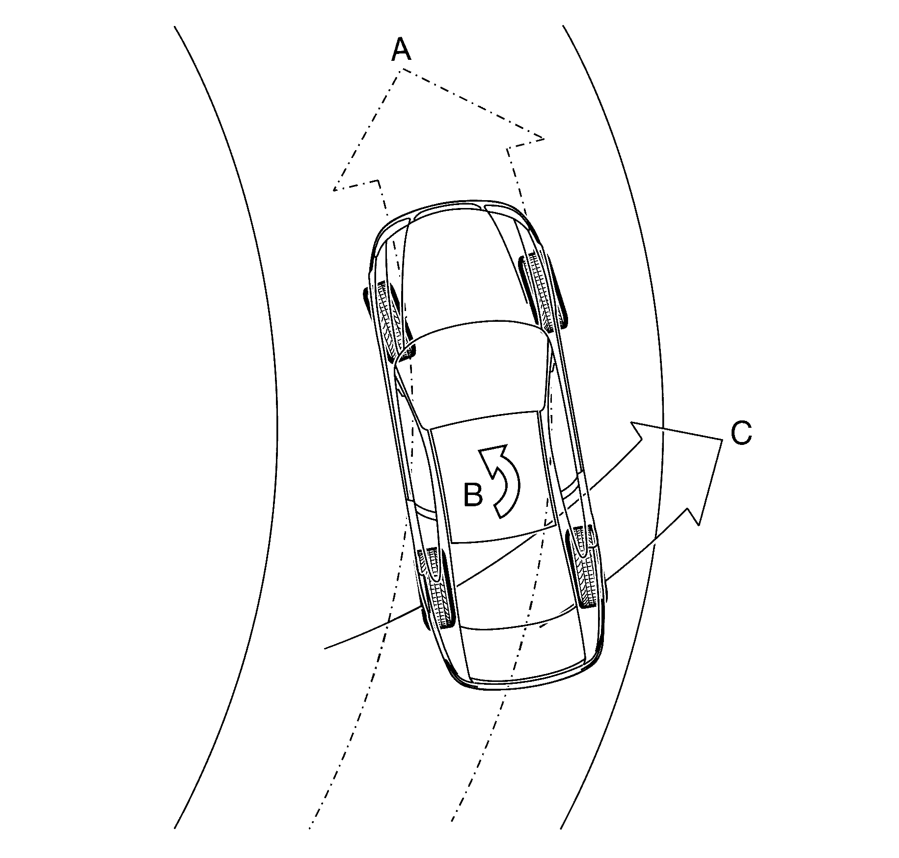
Brake Pressure Modulator Valve


Object Number: 1943589  Size: SH
(1)Brake pressure modulator valve
(2)Return Pump
(3)Accumulator
(4)Brake Caliper
(5)Brake Master Cylinder
(6)Inlet Valves
(7)Outlet Valves
(8)Isolating Solenoid Valve
(9)Priming Solenoid Valve
(a)Normal (conventional) brake fluid pressure
(b)Stopped brake fluid pressure flow (solenoid valve closed)
(c)Pump generated brake fluid pressure flow
(d)Brake pedal applied
(m)Motor

Important: The illustration shows the brake pressure modulator valve components while in ABS pressure reducing phase. Refer to this illustration for the following hydraulic components.

The brake pressure modulator valve (BPMV) assembly (1) modulates the brake fluid pressure (A) based on the control signal sent by the electronic brake control module (EBCM).

To allow individual control of each wheel brake fluid circuit, a four-channel circuit configuration with a front/rear split is used. Each of the brake fluid circuits are hydraulically isolated, which enables continued braking ability if a leak develops in any of the brake fluid circuits. The BPMV components consist of the following:

    • Two return pumps (2) - Each pump draws excess brake fluid from the accumulators (3) and brake calipers (4) allowing the hydraulic modulator to return brake fluid to the brake master cylinder (5) against brake fluid pressure (C) during the ABS-TCS/ESP pressure reducing phase. In addition, the return pump applies pressure to the brake calipers during the ABS brake intervention phase.
    • One electric motor (M) - The electric motor drives the return pump.
    • Two accumulators - The accumulators store the excess brake fluid during the ABS-TCS/ESP pressure reducing phase that enables the hydraulic modulator to apply instant pressure reduction.
    • Four inlet valves (6) - At rest position, each inlet valve allows brake fluid pressure to be applied to the brake callipers. When active, each inlet valve isolates a brake calliper from the brake master cylinder.
    • Four outlet valves (7) - At rest position, each outlet valve isolates a brake calliper from the accumulator and return pump. When active, each outlet valve directs excess brake fluid to the accumulator and return pump that allows pressure reduction.
    • Two isolating solenoid valves (8) - The isolating solenoid valves isolate the rear brake fluid circuits from the brake master cylinder which prevents the return of the brake fluid to the brake master cylinder during TCS operation.
    • Two rear priming valves (9) - Allow brake fluid to be drawn from the brake master cylinder into the hydraulic pump during TCS operation.

Wheel Speed Sensor

Active wheel speed sensors are fitted to this vehicle. Active wheel speed sensors are direction sensitive.

The wheel speed sensor receives a 12-volt power supply voltage from the electronic brake control module (EBCM). The wheel speed sensor contains an integrated circuit containing a magneto-resistive bridge. Wheel rotation changes the positioning of the tone wheel and the wheel speed sensor's magnetic field and varies the magneto-resistive bridge resistance. The wheel speed sensor's integrated circuit modifies and amplifies the varying resistance into a direct current (DC) square wave signal. Therefore as the wheel spins, the wheel speed sensor changes the voltage and current level output signal to the EBCM. The wheel speed sensor always has a current flow on the output signal circuit to complete the wheel speed sensor's ground path and for EBCM diagnostics. The EBCM uses the frequency of the square wave signal to calculate the wheel speed.

Brake Pedal Position Sensor

The brake pedal position sensor (1) is a normally open switch that closes when the brake pedal is depressed.


Object Number: 1943576  Size: SH

The electronic brake control module (EBCM) uses the stop lamp switch signal voltage to determine when the brake pedal is depressed.

Electronic Stability Program (ESP) Switch


Object Number: 1943579  Size: SH

The ESP switch incorporates traction control (TCS) which is part of a multi function centre console switch assembly and is located in the console as shown above.

The ESP switch is a momentary contact switch that sends a ground output signal to the body control module (BCM).

The BCM sends a signal to the EBCM via the serial data bus to perform the following functions:

    • Pressing the ESP switch once deactivates both TCS and ESP for the duration of that ignition cycle. ABS will still function normally when the TCS and ESP is deactivated.
    • Pressing the ESP switch again when the TCS and ESP is deactivated, activates the TCS and ESP.
    • Pressing the ESP switch for more than 60 seconds will be interpreted as a short circuit. Consequently, a DTC will be logged and the TCS and ESP will be deactivated for the duration of that ignition cycle.

If there are no current TCS/ESP DTC's logged, the ESP activates at the next ignition cycle.

Yaw Rate Sensor Assembly

The yaw-rate sensor assembly (1) comprises of a yaw-rate sensor and a lateral acceleration sensor.


Object Number: 1943594  Size: SH
    • The yaw-rate sensor produces a signal output voltage that corresponds to a vehicle rotation around its vertical axis.
    • The lateral acceleration sensor produces a signal output voltage that corresponds to a vehicle lateral acceleration.

The EBCM uses the output signal voltage of the yaw-rate sensor and the acceleration sensor in conjunction with the wheel speed sensor signal output voltage and serial data output signal of the steering angle sensor, to support the calculation of actual vehicle behavior as compared to the driver intended direction.

Lateral Acceleration Sensor


Object Number: 1943598  Size: SH

Important: This illustration represents the lateral acceleration sensor in symbolic form, which aims to show the operation of the acceleration sensor in a simplified manner.

The lateral acceleration sensor consists of the following components:

    • Differential capacitors connected to the fixed side plates (1).
    • Mass plate (2) suspended by springs (3) about its centre of mass, which moves in response to vehicle lateral acceleration.

When the vehicle is stationary (View A), the distance between the mass plate and the 2 side plates are equal. Therefore, the capacitance between the 2 capacitors is the same and the acceleration sensor signal voltage is zero.

As the vehicle accelerates (View B), the side plates move with the vehicle (C) while the mass plate, which is suspended by springs tends to move in the opposite direction. Therefore, the distance between the side plates and the mass plates changes in proportion to the level of acceleration.

This changes the capacitance between the 2 capacitors causing the acceleration sensor to produce a signal voltage with an amplitude proportional to the movement of the mass plates.

Yaw Rate Sensor


Object Number: 1943600  Size: SH

Important: This illustration represent the yaw rate sensor in symbolic form, which shows the operation of the yaw rate sensor in a simplified manner.

The yaw-rate sensor consists of the following components:

    • Two oscillating plates (1) suspended by springs (2) around its center of mass.
    • An acceleration sensor (3) incorporated within the oscillating plates.
    • Permanent magnets, which project magnetic field to the oscillating plates.

While in the presence of a magnetic field, electric current is applied to the oscillating plates, which causes the plates to move at a constant amplitude (W).

When the vehicle is driving in a straight-ahead direction and there are not lateral forces applied to the acceleration sensors, the distance between the mass plates (4) and the side plates of the acceleration sensors are equal (5). Therefore, the capacitance between the capacitors are the same and the acceleration sensor signal voltage is zero.

When the vehicle rotates around its vertical axis, the following situation occurs.


Object Number: 1943592  Size: SH
    • With the exception of the mass plates (1), the yaw-rate sensor (2), which is firmly attached to the vehicle rotates with the vehicle (Z).
    • The mass plates, which are suspended by springs (3) and moves along with the oscillating plates (4), tend to float in its current position while the fixed side plates (5) rotate with the vehicle. Therefore, the distance between the fixed side plates and the mass plates of the acceleration sensor changes in proportion to the level of vehicle rotation around its vertical axis.
    • This changes the capacitance between the capacitors causing the acceleration sensor to produce a signal voltage with an amplitude proportional to the movement of the mass plates.

The evaluation circuit of the yaw-rate sensor compares and evaluates the output signal of both acceleration sensors to calculate the level of vehicle rotation around its vertical axis.

Steering Angle Sensor

The steering angle sensor provides a signal output that represents the steering wheel degree of rotation. The EBCM uses this information to calculate the driver intended driving direction. The steering angle sensor contains:


Object Number: 1943602  Size: SH
    • Gear Wheel (1).
    • Measuring Gears (2).
    • Measuring Gear Magnets (3).
    • Evaluation Circuit (4).
    • Anisotropic Magneto Resistive (AMR) Integrated Circuit (IC) (5).

The anisotropic magneto resistive integrated circuit (AMRIC) (1) comprises of 8 AMR elements (2) which are configured to form 2 Wheatstone bridges (3).


Object Number: 1943614  Size: SH

One of the Wheatstone bridges (4) is 45 degrees offset from the other to enable the AMR IC to produce sine (5) and cosine (6) output signal.

The AMR elements change resistance that corresponds to the changes in the angle of magnetic field projected to the AMR IC, regardless of the polarity of the magnetic field.

The evaluation circuit of the steering angle sensor evaluated and combines the output signal of the AMR IC to produce two identical linear output (A) that represents the 360 degrees angular rotation of the magnetic field.

The omni polarity of the AMR elements limits the signal output range of a single AMR IC from 0-180 degrees.

Steering Angle Sensor Layout

To increase the output signal range of the steering angle sensor, and enable it to produce an output signal that can represent the ±760 degrees of steering wheel rotation, 2 AMR ICs are fitted to the steering angle sensor.


Object Number: 1943605  Size: SH

The magnets (1) that project magnetic fields to the AMR ICs are mounted on the primary measuring gear (2) and secondary measuring gear (3).

The secondary gear has 2 less teeth when compared against the primary measuring gear. This causes the measuring gears to rotate at a different ratio.

Steering Angle Sensor Operation

The angular orientation of the magnetic fields produced by the measuring gear magnets (1) corresponds to the degree of steering wheel angular position.


Object Number: 1943603  Size: SH

This magnetic field changes the resistance value of the AMR elements, which enable the AMR ICs (2) to produce a pair of signal outputs (3).

The difference in the rotational ratio between the measuring gears causes the signal output of the second AMR IC (A) to be shorter in range when compared against the signal output of the first AMR IC (B).

The evaluation circuit (4) compares and evaluates this difference, and the rate of change between the output signals of the AMR ICs, at parallel points (5) to calculate that precise steering wheel angular position.

Antilock Brake System Operation

The antilock braking system (ABS) prevents wheel lock-up during hard or emergency braking by modulating the brake fluid pressure applied to the appropriate wheels. The ABS cycles through the following phases when the electronic brake control module (EBCM) detects the beginning of the wheel lock-up:

    • Maintaining pressure.
    • Reducing pressure.
    • Increasing pressure.

Important: The following are conditions that may be experienced when the ABS is active and are considered normal:

   • During ABS controlled braking, the braking pressure of the affected wheel is automatically adjusted to prevent wheel lock-up, regardless of pressure applied to the brake pedal.
   • A series of rapid pulsations are felt through the brake pedal. These pulsations occur as solenoid valves within the hydraulic modulator changes position to modulate the brake hydraulic pressure.
   • A ticking or popping noise in the hydraulic modulator occurs as the hydraulic modulator solenoid valves cycle rapidly to modulate the hydraulic brake pressure.
   • Intermittent chirping noises may be heard as the tyres approach slipping on dry pavement.
   • Electric motor and pump noise and rapid brake pedal pulsation caused by the operation of the hydraulic modulator pump during the ABS reducing or increasing pressure phase or the EBCM self-test.

ABS Phase - Maintaining Pressure

The EBCM closes the inlet valve and keeps the outlet valve closed in order to isolate the system when wheel slip occurs. This maintains the pressure steady on the brake so that the hydraulic pressure does not increase or decrease.

ABS Phase - Reducing Pressure

The EBCM decreases the pressure to individual wheels during a deceleration when wheel slip occurs. The inlet valve is closed and the outlet valve is opened. The excess fluid is stored in the accumulator until the return pump can return the fluid to the master cylinder.

ABS Phase - Increasing Pressure

The EBCM increases the pressure to individual wheels during a deceleration in order to reduce the speed of the wheel. The inlet valve is opened and the outlet valve is closed. The increased pressure is delivered from the master cylinder.

Electronic Brake-Force Distribution System

The electronic brake-force distribution (EBD) system is part of the ABS software programmed into the electronic brake control module (EBCM). It is designed to replace the rear brake proportioning valve in reducing rear wheel slip during moderate braking.

The EBD system utilises the existing ABS active controls to regulate the vehicle's rear brake fluid pressure. This enables the EBD system to provide dynamic front to rear brake proportioning under various vehicle loads, driving manoeuvres, or road conditions.

In some situations, when the EBD system is activated, a brake pedal height drop of approximately 10 mm will be experienced when the driver varies the brake pedal pressure while performing brake stops. This is caused by the hydraulic modulator performing an adjustment on the rear brake fluid pressure and is considered normal.

EBD System Keep Alive Function

The EBD system plays an important role in vehicle stability during braking. For this reason, the EBD system has a Keep Alive Function integrated in its software. When the EBCM detects a fault in the ABS, depending on the type of fault, certain parts of the system are kept alive. This allows the EBD system to apply some rear wheel brake proportioning even under certain ABS faults.

Traction Control System

The traction control system (TCS) utilises the active braking controls in the ABS and the engine torque reduction function of the engine management system to prevent longitudinal wheel spin during vehicle acceleration.

When drive wheel slip is noted while the brake is not applied, the EBCM will enter traction control mode.

First, the EBCM requests the ECM to reduce the amount of torque to the drive wheels via the requested torque signal circuit. The ECM reduces torque to the drive wheels by retarding spark timing and turning off fuel injectors. The ECM reports the amount torque delivered to the drive wheels via the delivered torque signal circuit.

If the engine torque reduction does not abolish drive wheel slip, the EBCM will actively apply the drive wheel brakes. During traction control braking, hydraulic pressure in each drive wheel circuit is controlled to prevent the drive wheels from slipping. The master cylinder isolation valve closes in order to isolate the master cylinder from the rest of the hydraulic system. The prime valve then opens in order to allow the pump to accumulate brake fluid in order to build hydraulic pressure for braking. The drive wheel inlet and outlet solenoid valves then open and close in order to perform the following functions:

    • Pressure increase.
    • Pressure hold.
    • Pressure decrease.

If at any time during TCS mode the brakes are manually applied, the brake switch sends a signal to the EBCM to exit the TCS brake intervention mode and allow for manual braking.

Electronic Stability Program

The electronic stability program (ESP) is designed to provide optimum vehicle stability and steering control during high speed cornering or when driving on a slippery road surface.

Yaw rate is the rate of rotation about the vehicle's vertical axis. The VSES is activated when the EBCM determines that the desired yaw rate does not match the actual yaw rate as measured by the yaw rate sensor.

The desired yaw rate is calculated from the following parameters:

    • The position of the steering wheel.
    • The speed of the vehicle.
    • The lateral, or sideways acceleration of the vehicle.

The difference between the desired yaw rate and the actual yaw rate is the yaw rate error, which is a measurement of oversteer or understeer. If the yaw rate error becomes too large, the EBCM attempts to correct the vehicle's yaw motion by applying differential braking to the appropriate wheel. The amount of differential braking applied to the left or right front wheel is based on both the yaw rate error and side slip rate error.

The VSES activations generally occur during aggressive driving, in turns or on bumpy roads without much use of the accelerator pedal. When braking during VSES activation, the pedal pulsations feel different than the ABS pedal pulsations. The brake pedal pulsates at a higher frequency during VSES activation.

The ESP incorporates the following components:

    • Steering angle sensor to determine driver steering input, which the EBCM uses to support the calculation of intended vehicle direction.
    • Yaw rate sensor to measure vehicle rotation around its vertical axis, which the EBCM uses to support the calculation of actual vehicle behaviour.
    • Active braking and engine torque reduction functionality of the TCS to prevent wheel spin.

When the ESP detects a lateral wheel slip or when the calculated vehicle direction deviates from the actual vehicle direction, the ESP utilises the engine torque reduction functionality and the active braking controls in the ABS-TCS to stabilise and steer the vehicle to the correct direction.

ESP Engine Torque Reduction

The ESP monitors the wheel speed sensor, yaw-rate sensor and the steering angle sensor to determine lateral wheel slip. When the ESP detects a lateral wheel slip, the ESP initially utilises the torque reduction functionality of the TCS and sends a serial data communication signal to the engine control module (ECM) requesting engine torque reduction. In addition, if the ESP still detects a lateral wheel slip, the ESP applies active brake intervention.

ESP Brake Intervention

The ESP applies active brake intervention when the EBCM receives the following input signals and determines the vehicle is beginning to understeer.


Object Number: 1943606  Size: SH
    • The steering angle sensor sends a signal to the EBCM the driver intends to steer in direction (A).
    • The yaw rate sensor detects the vehicle begins to spin (B) with the front of the vehicle beginning to slide in direction (C).

The ESP uses the existing active braking control in the ABS-TCS to apply a calculated braking force to one or both inner wheels (1) of the vehicle to stabilise and steer the vehicle to the intended direction.


Object Number: 1943607  Size: SH

Important: Applying brake-force to the inner wheel (1) slows down the inner side of the vehicle, which induces the vehicle to rotate on its vertical axis (A).

The EBCM monitors and compares signals from the yaw-rate sensor, steering angle sensor and each wheel speed sensor to determine wheel slip. If the EBCM detects the beginning of a vehicle understeer condition, the EBCM sends the following signal to the hydraulic modulator to:

    • Close the front and rear isolating valves.
    • Open the front and rear prime valves.
    • Close the front right and rear right inlet valves.
    • Operate the hydraulic modulator pump.

This results in the following actions:

    • The rear isolation valve is closed to isolate the rear brake fluid circuits from the master cylinder and prevent the brake fluid returning to the brake master cylinder when the hydraulic pump builds-up the brake fluid pressure.
    • The front right and rear right inlet valves are closed to isolate the right wheel hydraulic circuits, allowing the hydraulic modulator to supply brake fluid pressure only to the left wheels.
    • The rear priming valve is open to allow fluid to be drawn from the master cylinder into the hydraulic pump.
    • The hydraulic pump applies appropriate brake fluid pressure to the left brake callipers to steer the vehicle to the intended direction.
    • The hydraulic modulator modulates the front left and rear left inlet valves and outlet valves to assist in obtaining maximum road surface traction in the same manner as in the TCS Mode.

       Important: If at any time during the ESP Mode the brakes are manually applied, the brake switch sends a signal to the EBCM to exit the ESP Brake Intervention Mode and allow normal braking.

The ESP applies active brake intervention when the EBCM receives the following input signals and determines the vehicle is beginning to oversteer.


Object Number: 1943608  Size: SH
    • The steering angle sensor sends a signal to the EBCM the driver intends to steer in direction (A).
    • The yaw-rate sensor detects the vehicle begins to spin (B) with the rear of the vehicle beginning to slide in direction (C).

The ESP uses the existing active braking control in the ABS-TCS to apply a calculated braking force to one or both outer wheels (1) of the vehicle to stabilise and steer the vehicle to the intended direction.


Object Number: 1943610  Size: SH

Applying brake-force to the outer wheel (1) slows down the outer side of the vehicle, which induces the inner wheel to rotate on its vertical axis (A).

The EBCM monitors and compares signals from the yaw-rate sensor, steering angle sensor and each wheel speed sensor to determine wheel slip. If the EBCM detects the beginning of a vehicle oversteer condition, the EBCM sends the following signal to the hydraulic modulator to:

    • Close the front and rear isolating valves.
    • Open the front and rear prime valves.
    • Close the front right and rear right inlet valves.
    • Operate the hydraulic modulator pump.

This results in the following actions:

    • The rear isolation valve is closed to isolate the rear brake fluid circuits from the master cylinder and prevent the brake fluid returning to the brake master cylinder when the hydraulic pump builds-up the brake fluid pressure.
    • The front left and rear left inlet valves are closed to isolate the right wheel hydraulic circuits, allowing the hydraulic modulator to supply brake fluid pressure only to the left wheels.
    • The rear priming valves are open to allow fluid to be drawn from the master cylinder to the hydraulic pump.
    • The hydraulic pump applies appropriate brake fluid pressure to the left brake callipers to stern the vehicle to the intended direction.
    • The hydraulic modulator modulates the front right and rear right inlet valves and outlet valves to assist in obtaining maximum road surface traction in the same manner as in the TCS Mode.

       Important: If at any time during the ESP Mode the brakes are manually applied, the brake switch sends a signal to the EBCM to exit the ESP Brake Intervention Mode and allow normal braking.