Engine Mount Replacement - Right Side for Isuzu Ascender - 2WD 2003
Tools Required
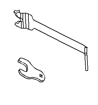
J 41240 Fan Clutch Remover and Installer
Removal Procedure
- Disconnect the battery negative cable. Refer to Battery Negative Cable Disconnection and Connection in Engine Electrical.
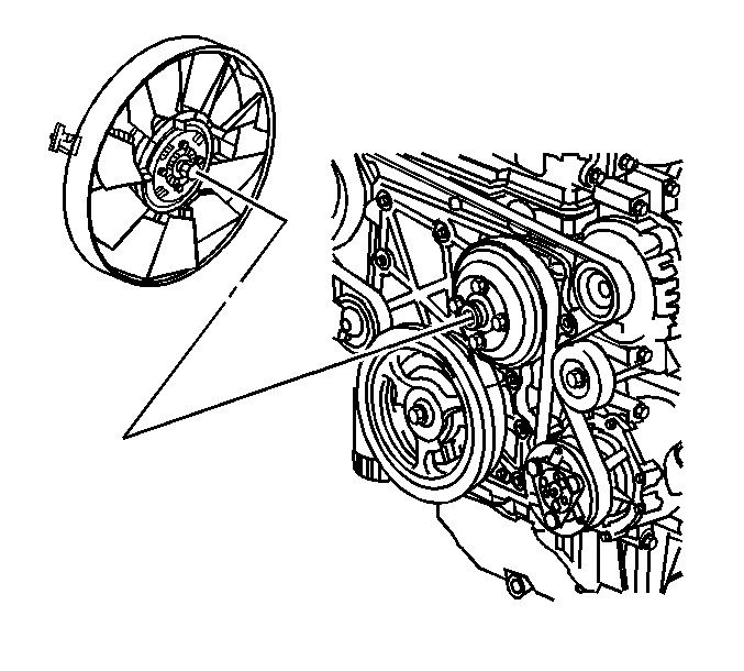
- Using the J 41240 to secure the water pump pulley. Loosen the cooling fan hub nut from the water pump shaft.
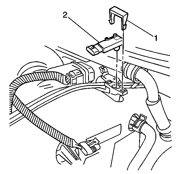
- Remove the MAP sensor electrical connector and retainer (1).
- Remove the MAP sensor (2).
- Remove the right shock module, if frame engine mount is being removed. Refer to Shock Absorber and Spring Assembly Replacement in Front Suspension.
- Remove the right and the left upper engine mount nuts.
- Raise the vehicle. Refer to Lifting and Jacking the Vehicle in General Information.
- Remove the right and the left lower engine mount nuts.
- Remove the engine protection shield mounting bolts.
- Remove the engine protection shield.
- Lower the vehicle and place a floor jack under the oil pan with a block of wood.
- Raise the engine with the jack just enough to clear the engine mount studs.
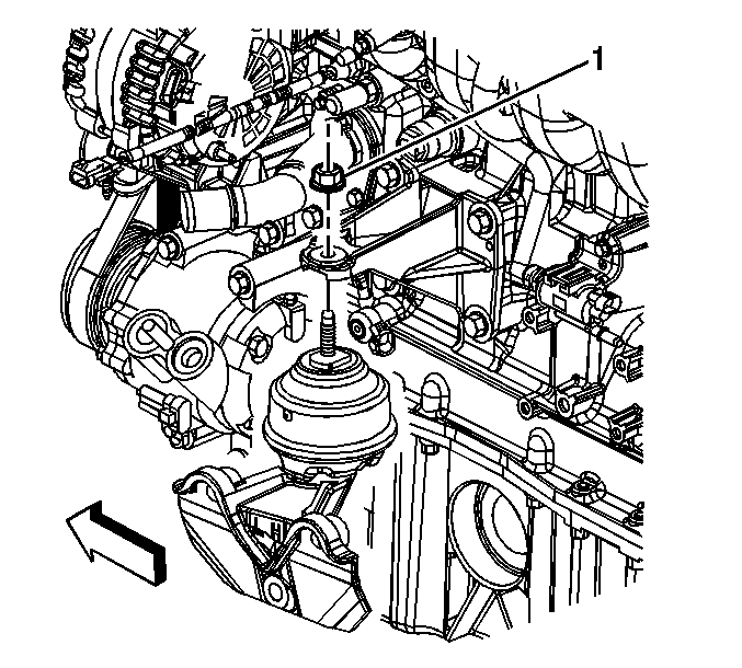
- Remove the right engine mount from the bracket.
- Note: Graphic shows left, right is similar.
- Remove the right engine mount bracket.
- Note: Graphic shows left, right is similar.
- Remove the right frame engine mount bracket, if required.
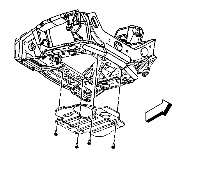
Important: When placing jack onto the oil pan, pay close attention to not damaging the oil level sender.
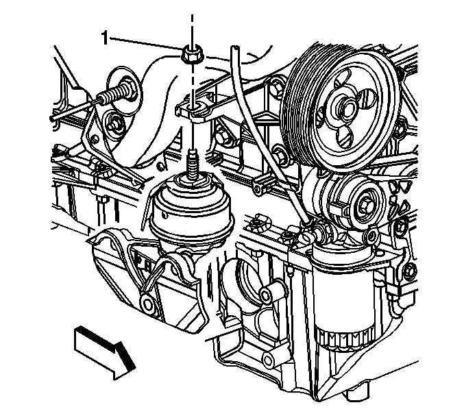
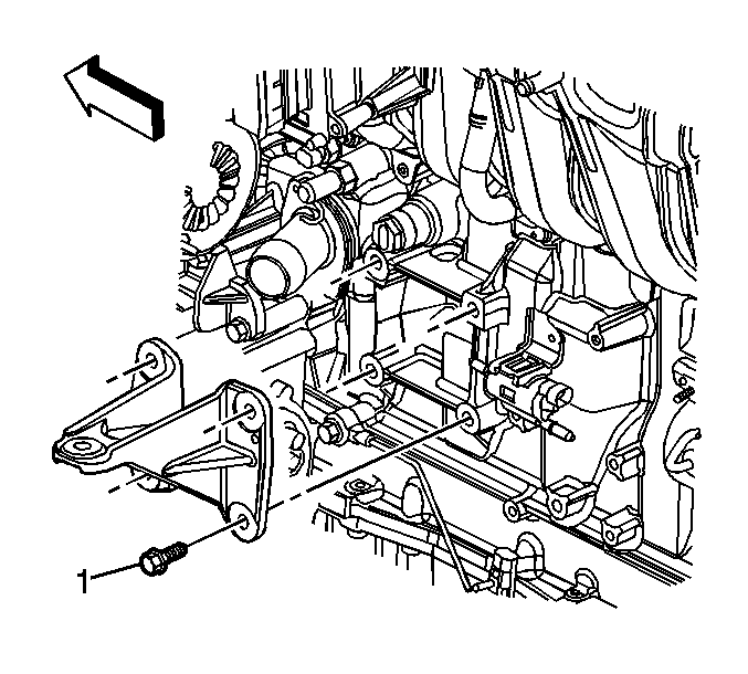
Remove the right engine mount bracket bolts.
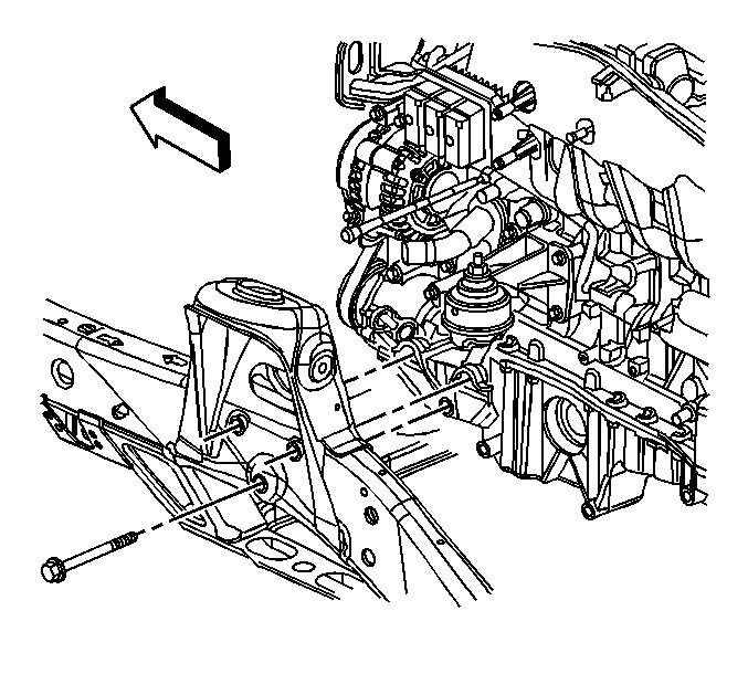
Remove the right frame engine mount bracket bolts, if required.
Installation Procedure
- Note: Graphic shows left, right is similar.
- Install the right frame engine mount bracket bolts, if removed.
- Note: Graphic shows left, right is similar.
- Install the right engine mount.
- Lower the engine onto the engine mounts.
- Install the right and the left upper engine mount nuts.
- Raise the vehicle and remove the floor jack from under the vehicle.
- Install the engine protection shield and secure with the bolts.
- Install the right and the left lower engine mount nuts.
- Lower the vehicle.
- Install the right shock module. Refer to Shock Absorber and Spring Assembly Replacement in Front Suspension.
- Install the MAP sensor (2).
- Install the MAP sensor retainer (1) and the electrical connector.
- Connect the cooling fan hub nut to the water pump shaft.
- Install the J 41240 to the water pump pulley and tighten the cooling fan hub nut.
- Connect the battery negative cable. Refer to Battery Negative Cable Disconnection and Connection .
Install the right frame engine mount bracket, if removed.
Notice: Use the correct fastener in the correct location. Replacement fasteners must be the correct part number for that application. Fasteners requiring replacement or fasteners requiring the use of thread locking compound or sealant are identified in the service procedure. Do not use paints, lubricants, or corrosion inhibitors on fasteners or fastener joint surfaces unless specified. These coatings affect fastener torque and joint clamping force and may damage the fastener. Use the correct tightening sequence and specifications when installing fasteners in order to avoid damage to parts and systems.
Tighten
Tighten the mount bracket bolts to 110 N·m (81 lb ft).
Install the right engine mount bracket and secure with the bolts (1).
Tighten
Tighten the engine mount bracket bolts to 50 N·m (37 lb ft).
Tighten
Tighten the upper engine mount nuts to 70 N·m (52 lb ft).
Tighten
Tighten the engine protection shield bolts to 25 N·m (18 lb ft).
Tighten
Tighten the lower engine mount nuts to 70 N·m (52 lb ft).
Tighten
Tighten the cooling fan hub nut to 56 N·m (41 lb ft).
