GM Service Manual Online
For 1990-2009 cars only
Figure 1:

Module Power, Ground, Serial Data, and MIL
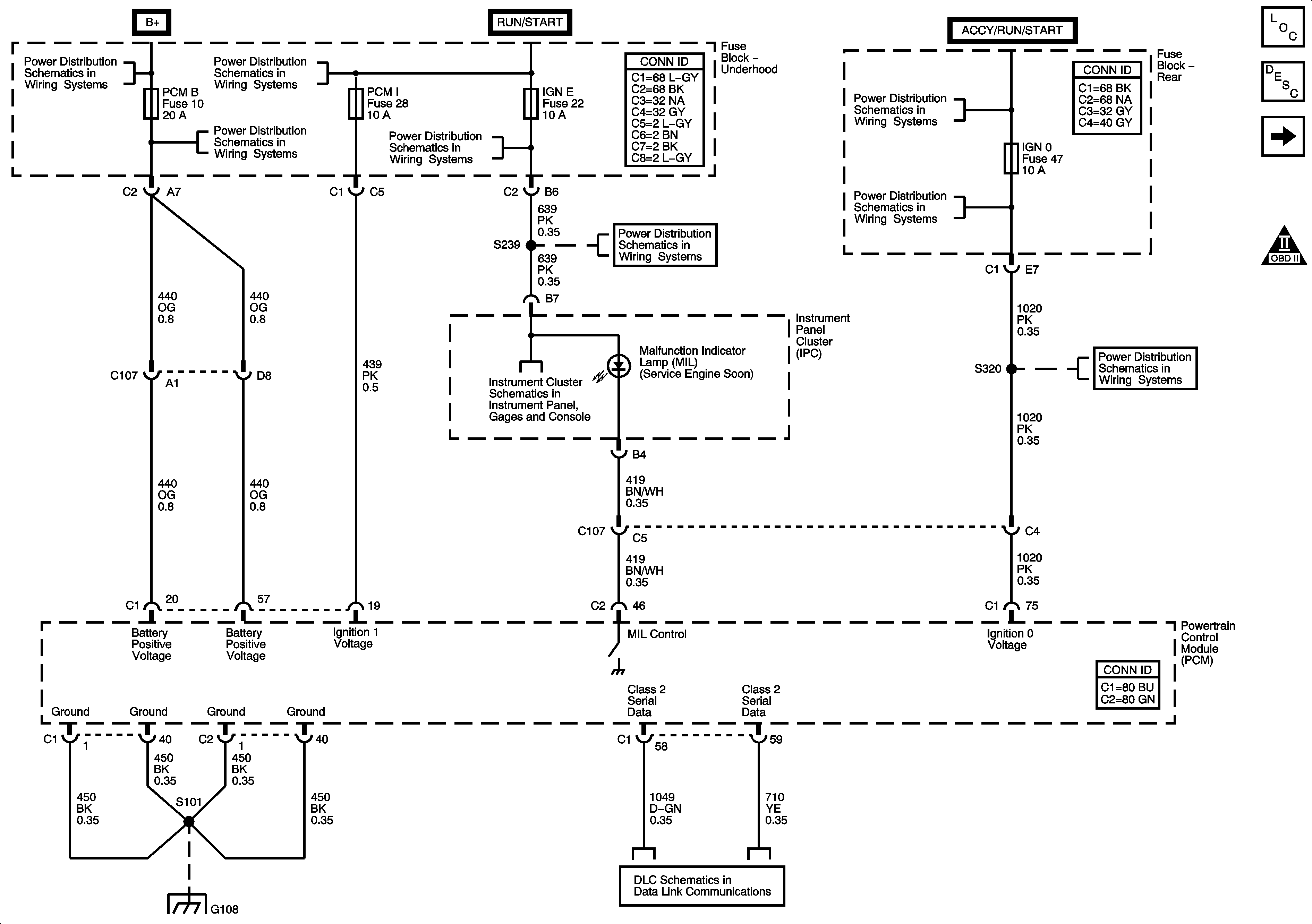

Object Number: 1251393  Size: FS
Master Electrical Component List
Powertrain Control Module Description
Fuse Block - Underhood, IGN 1 Relay
OBD II Symbol Description Notice
B+ Bus - Underhood Fuse Block
ACCY/RUN and RUN/START Bus Bars
COILS, AIR, EAP, TBC 1, PCM B, LOW HDLP-LT, LOW HDLP-RT, HI HDLP-LT, and HI HDLP-RT Fuses
IGN E, TBC IGN 1, BACKUP, BTSI, and TRLR B/U Fuses
ACCY/RUN/START, RUN, and START Bus Bars
IGN 0, TBC IG, TBC ACC, FRT WPR, and RAIN Fuses
IGN E, TBC IGN 1, BACKUP, BTSI, and TRLR B/U Fuses
IGN 0, TBC IG, TBC ACC, FRT WPR, and RAIN Fuses
Power, Ground, Serial Data, and MIL
G108
Power, Ground, Data Link Connector, and SP205
Figure 2:

Fuse Block - Underhood, IGN 1 Relay


Object Number: 1251394  Size: FS
Master Electrical Component List
Powertrain Control Module Description
Engine Data Sensors - 5 Volt and Low Reference
Module Power, Ground, Serial Data, and MIL
OBD II Symbol Description Notice
B+ Bus - Underhood Fuse Block
ACCY/RUN and RUN/START Bus Bars
G104, G105, and G107
Figure 3:

Engine Data Sensors - 5-Volt and Low Reference
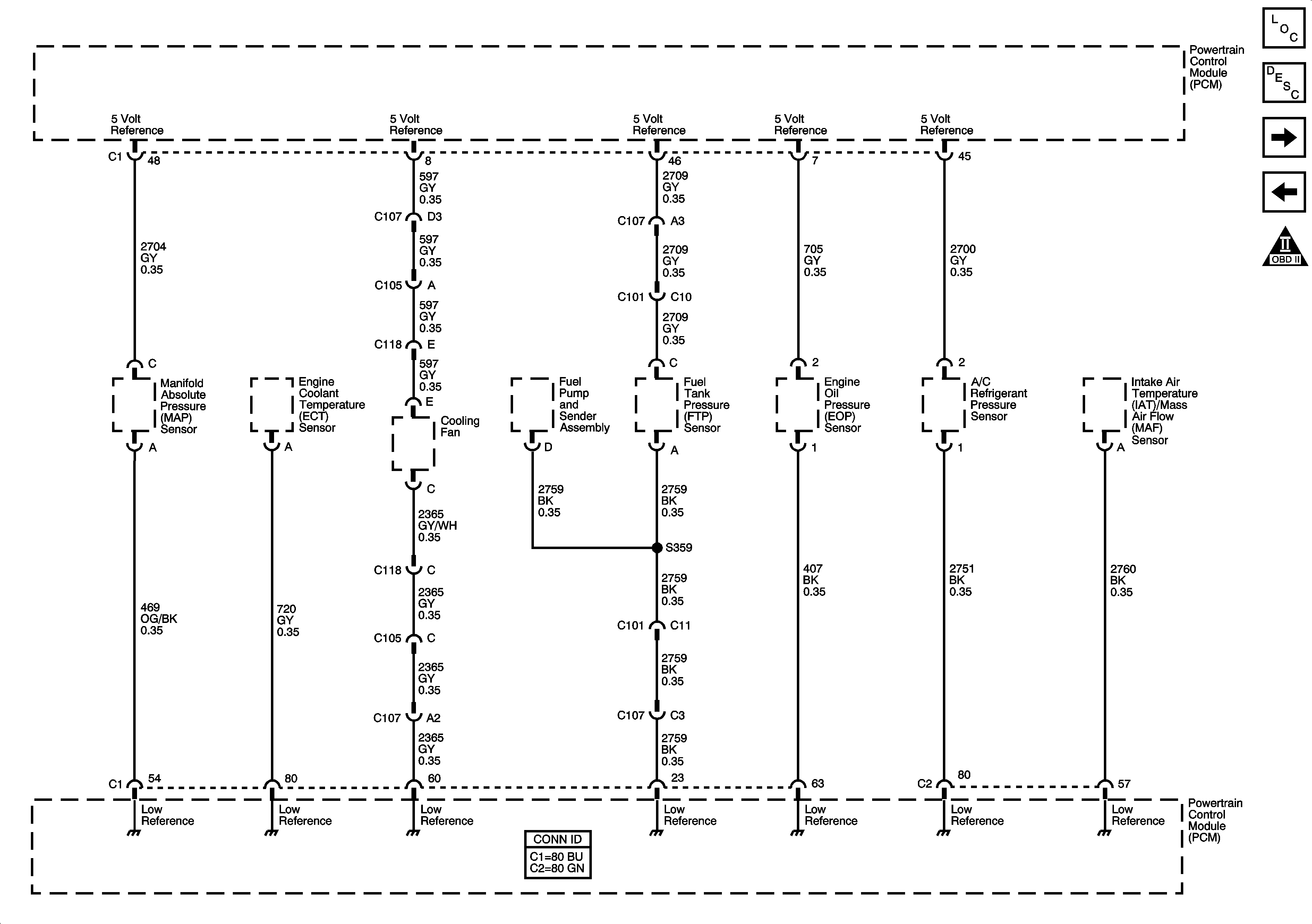

Object Number: 1251395  Size: FS
Master Electrical Component List
Powertrain Control Module Description
Engine Data Sensors - Pressure, Temperature, and VSS
Module Power, Ground, Serial Data, and MIL
OBD II Symbol Description Notice
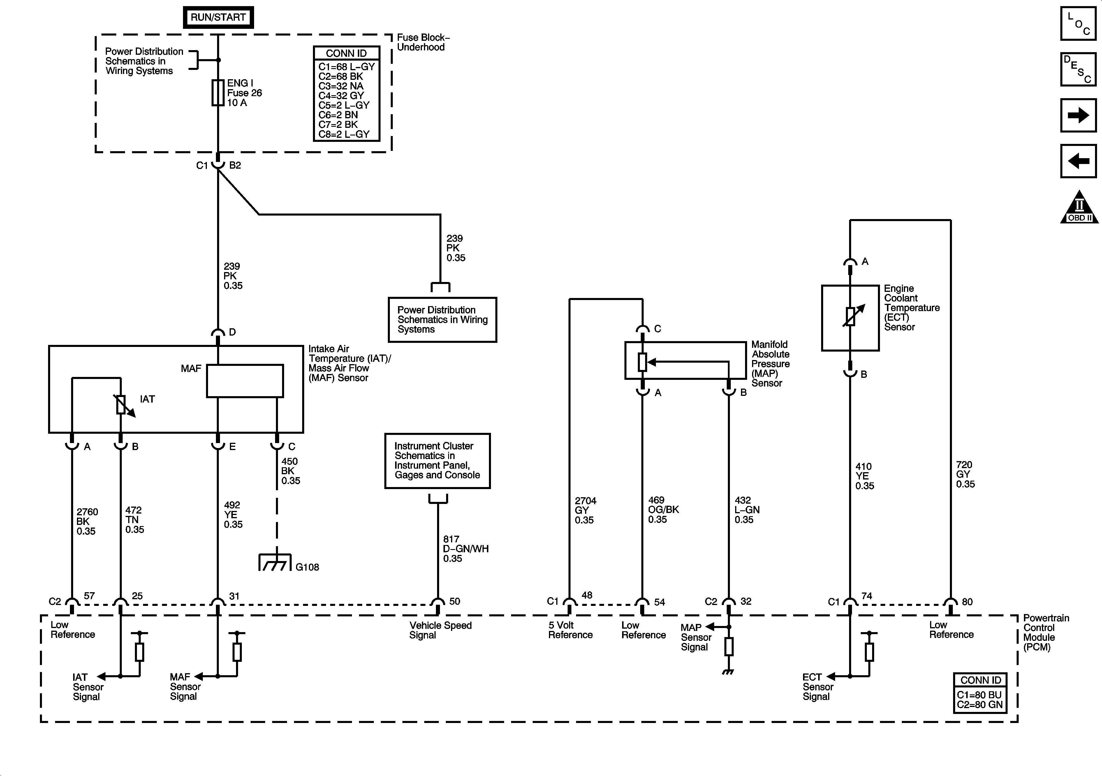
Figure 4:

Engine Data Sensors - Pressure, Temperature, and VSS


Object Number: 1251397  Size: FS
Master Electrical Component List
Powertrain Control Module Description
Engine Data Sensors - Oxygen Sensors
Engine Data Sensors - 5 Volt and Low Reference
OBD II Symbol Description Notice
ACCY/RUN and RUN/START Bus Bars
PCM I, O2A, O2B, and ENG I Fuses - 5.3L
Gages
G108
Figure 5:

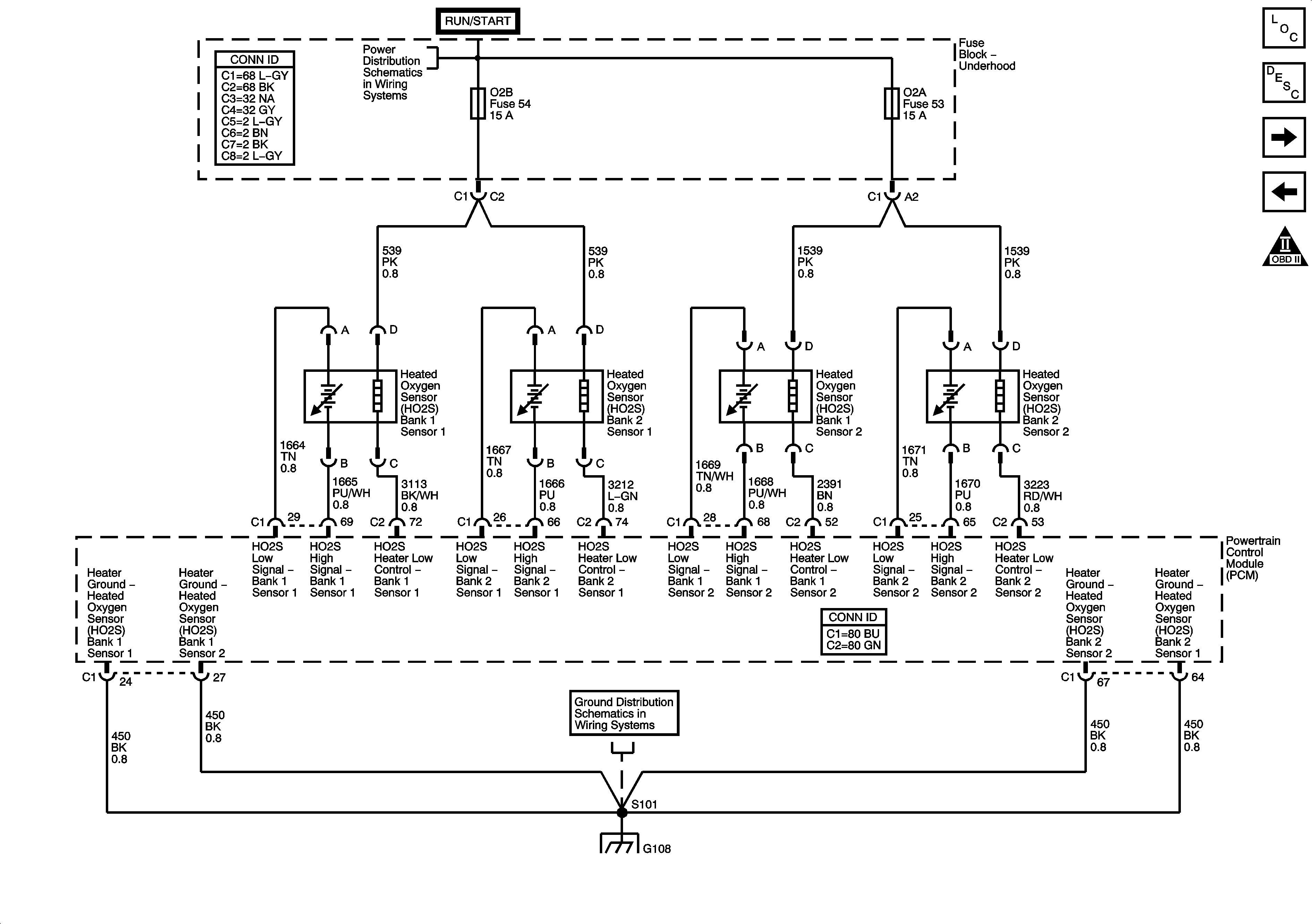
Engine Data Sensors - Oxygen Sensors


Object Number: 1251399  Size: FS
Master Electrical Component List
Powertrain Control Module Description
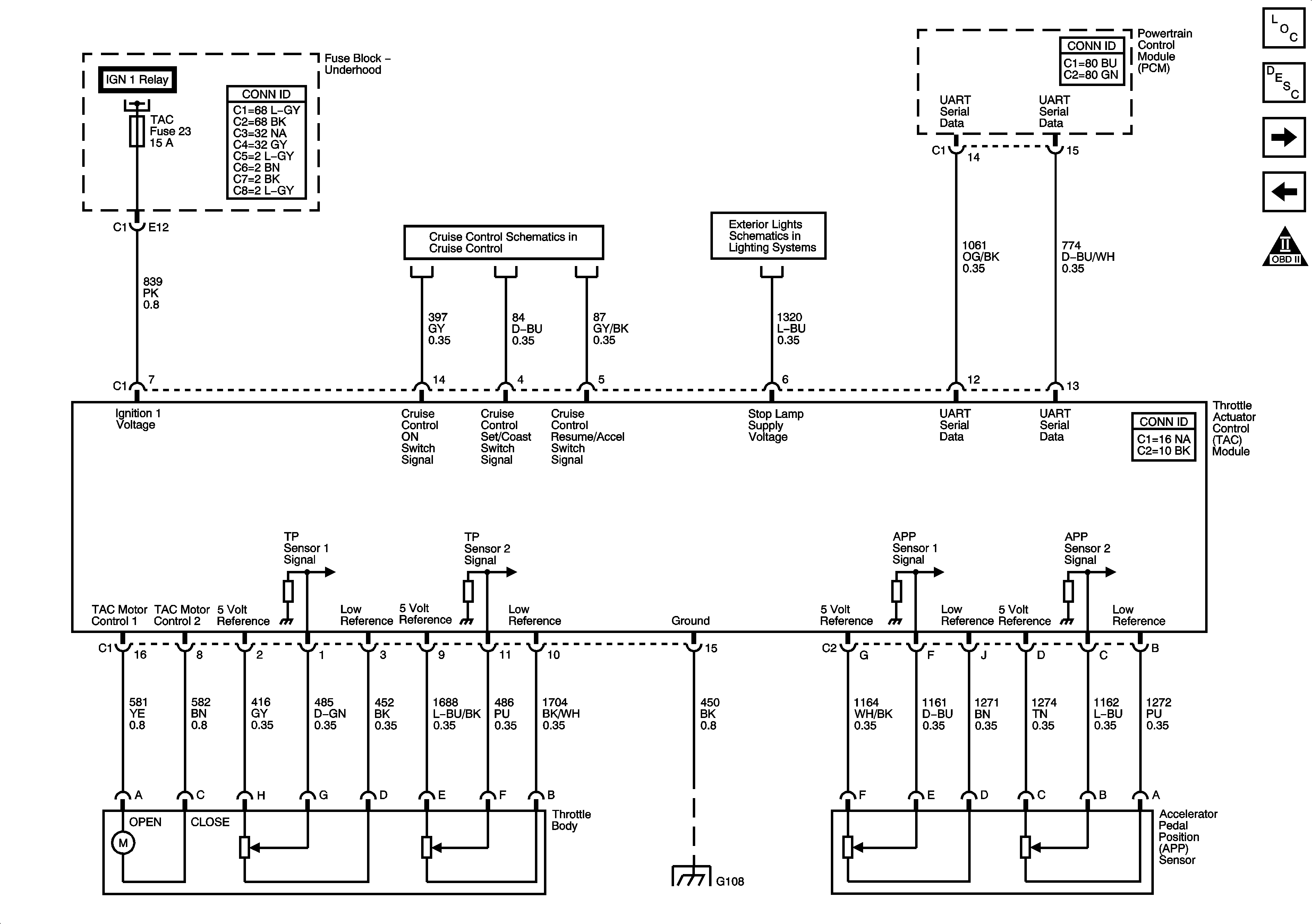
Engine Data Sensors - Throttle Actuator Controls
Engine Data Sensors - Pressure, Temperature, and VSS
OBD II Symbol Description Notice
ACCY/RUN and RUN/START Bus Bars
G108
G108
Figure 6:

Engine Data Sensors - Throttle Actuator Controls


Object Number: 1251400  Size: FS
Master Electrical Component List
Throttle Actuator Control (TAC) System Description
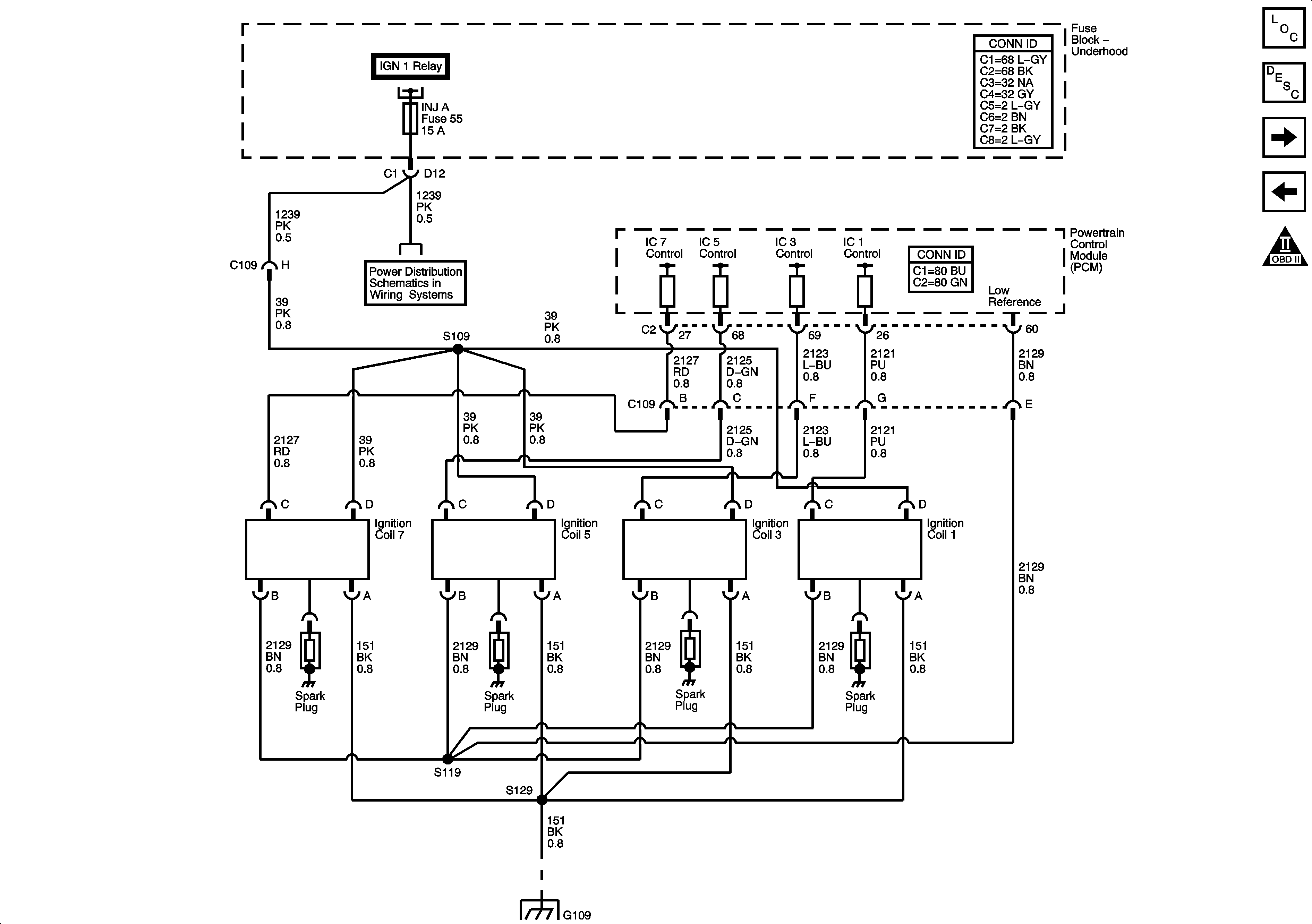
Ignition Controls - Ignition System Coils 1, 3, 5, 7
Engine Data Sensors - Oxygen Sensors
OBD II Symbol Description Notice
Fuse Block - Underhood, IGN 1 Relay
5.3L
Stop Lamps
G108
Figure 7:

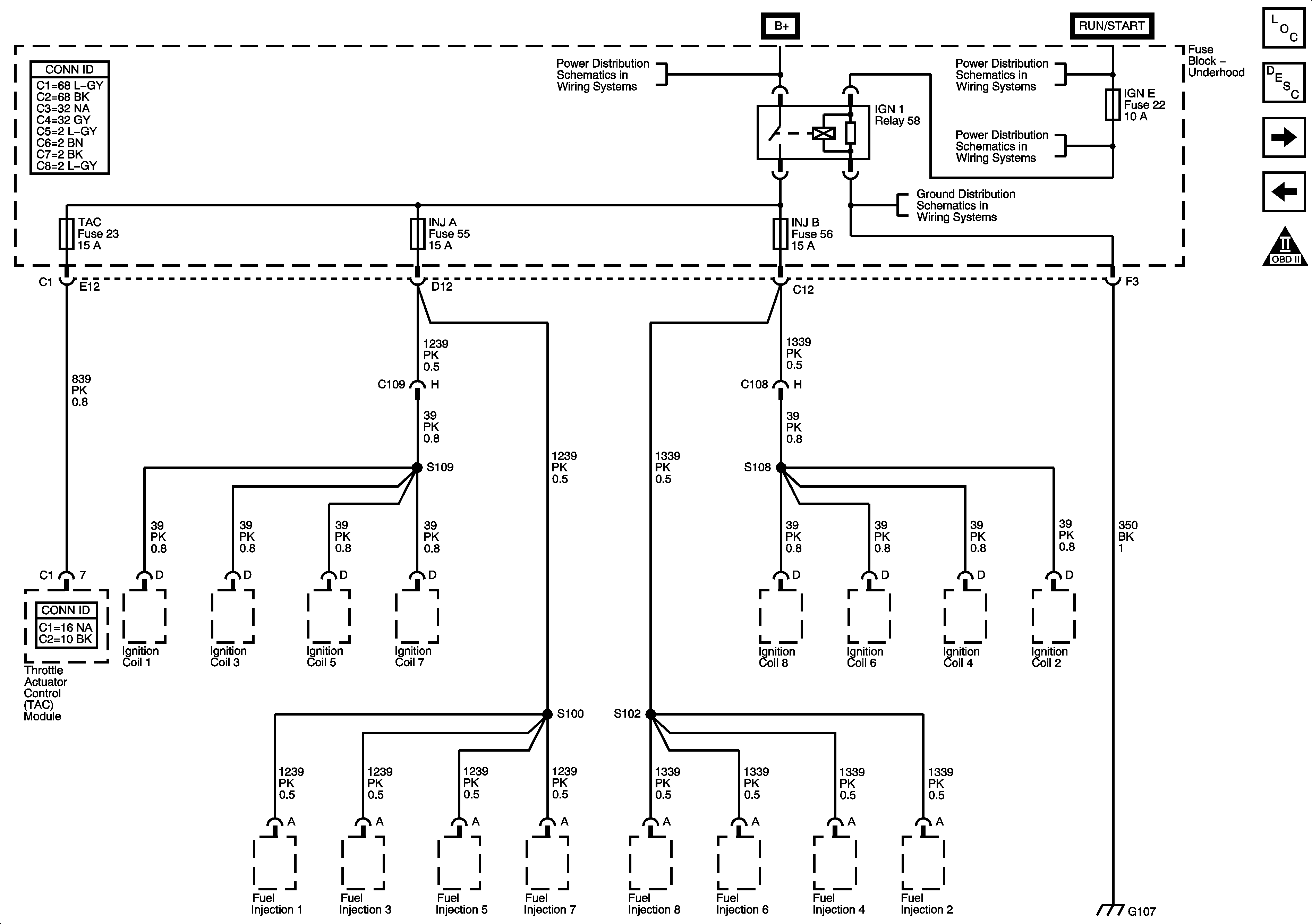
Ignition Controls - Ignition System Coils 1, 3, 5, 7


Object Number: 1251402  Size: FS
Master Electrical Component List
Electronic Ignition (EI) System Description
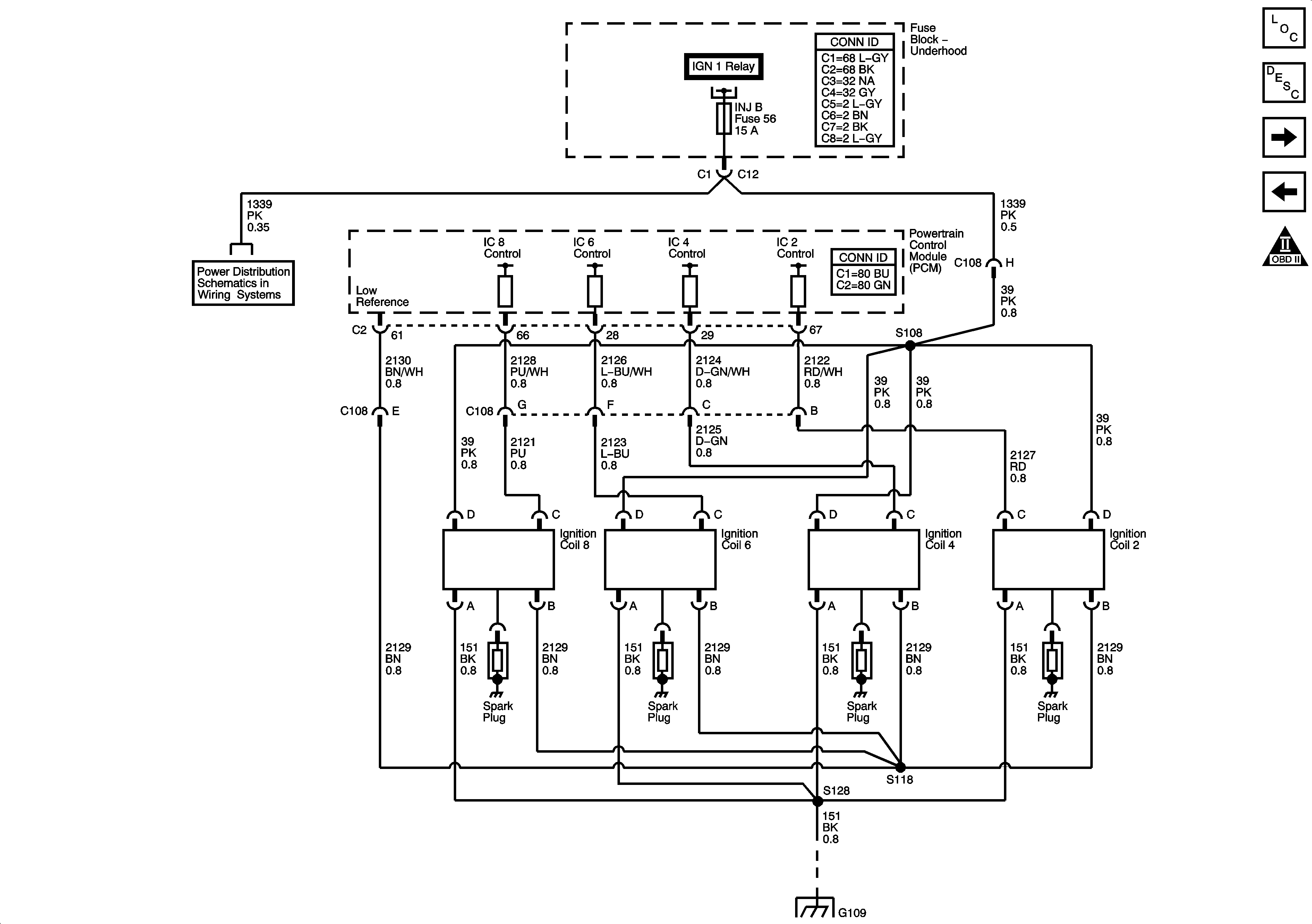
Ignition Controls - Ignition System Coils 2, 4, 6, 8
Engine Data Sensors - Throttle Actuator Controls
OBD II Symbol Description Notice
Fuse Block - Underhood, IGN 1 Relay
CANISTER VENT, TAC, INJ A and INJ B Fuses - 5.3L
G109
Figure 8:

Ignition Controls - Ignition System Coils 2, 4, 6, 8


Object Number: 1251403  Size: FS
Master Electrical Component List
Electronic Ignition (EI) System Description
Ignition Controls - Sensors
Ignition Controls - Ignition System Coils 1, 3, 5, 7
OBD II Symbol Description Notice
Fuse Block - Underhood, IGN 1 Relay
CANISTER VENT, TAC, INJ A and INJ B Fuses - 5.3L
G109
Figure 9:

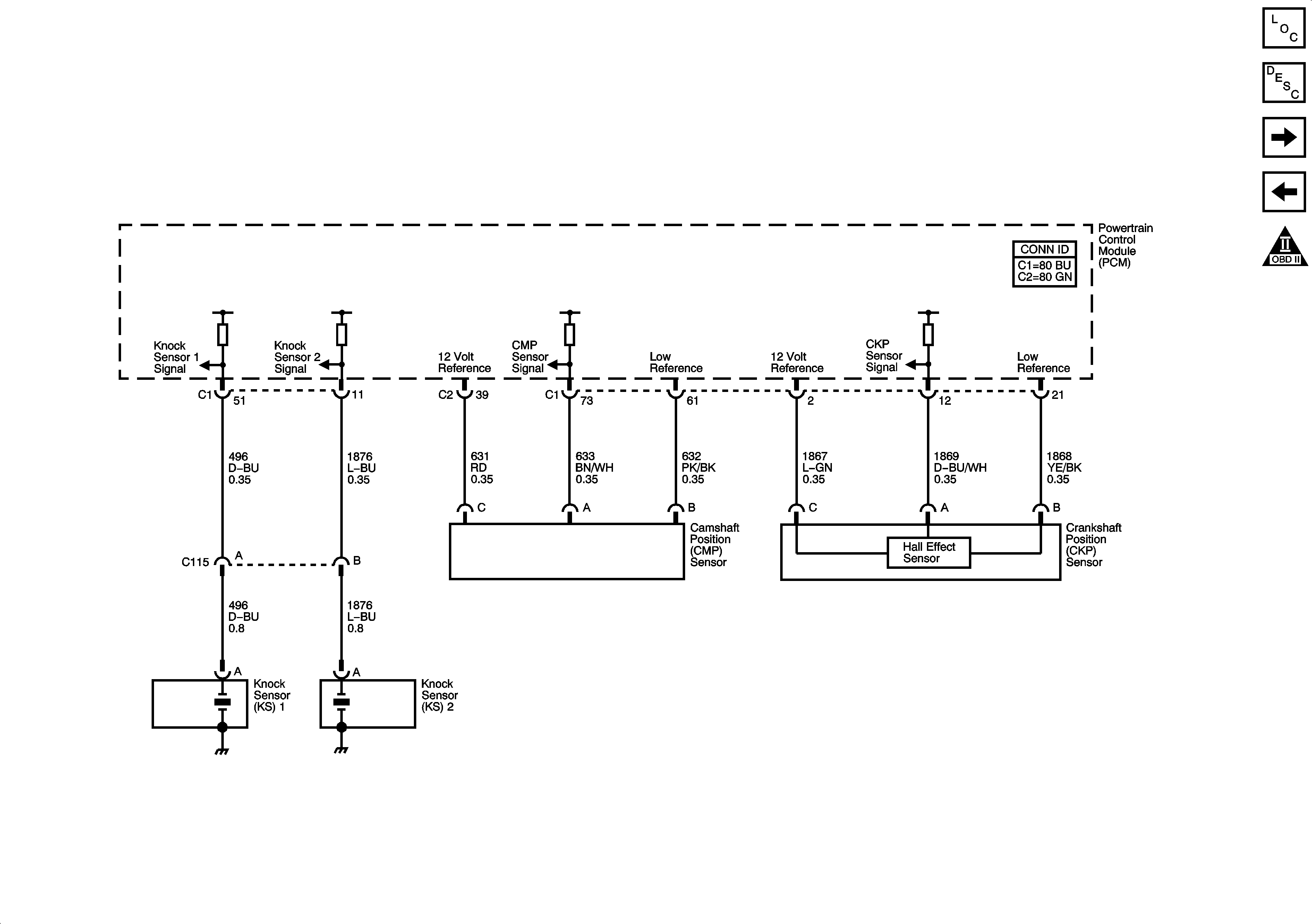
Ignition Controls - Sensors


Object Number: 1251405  Size: FS
Master Electrical Component List
Electronic Ignition (EI) System Description
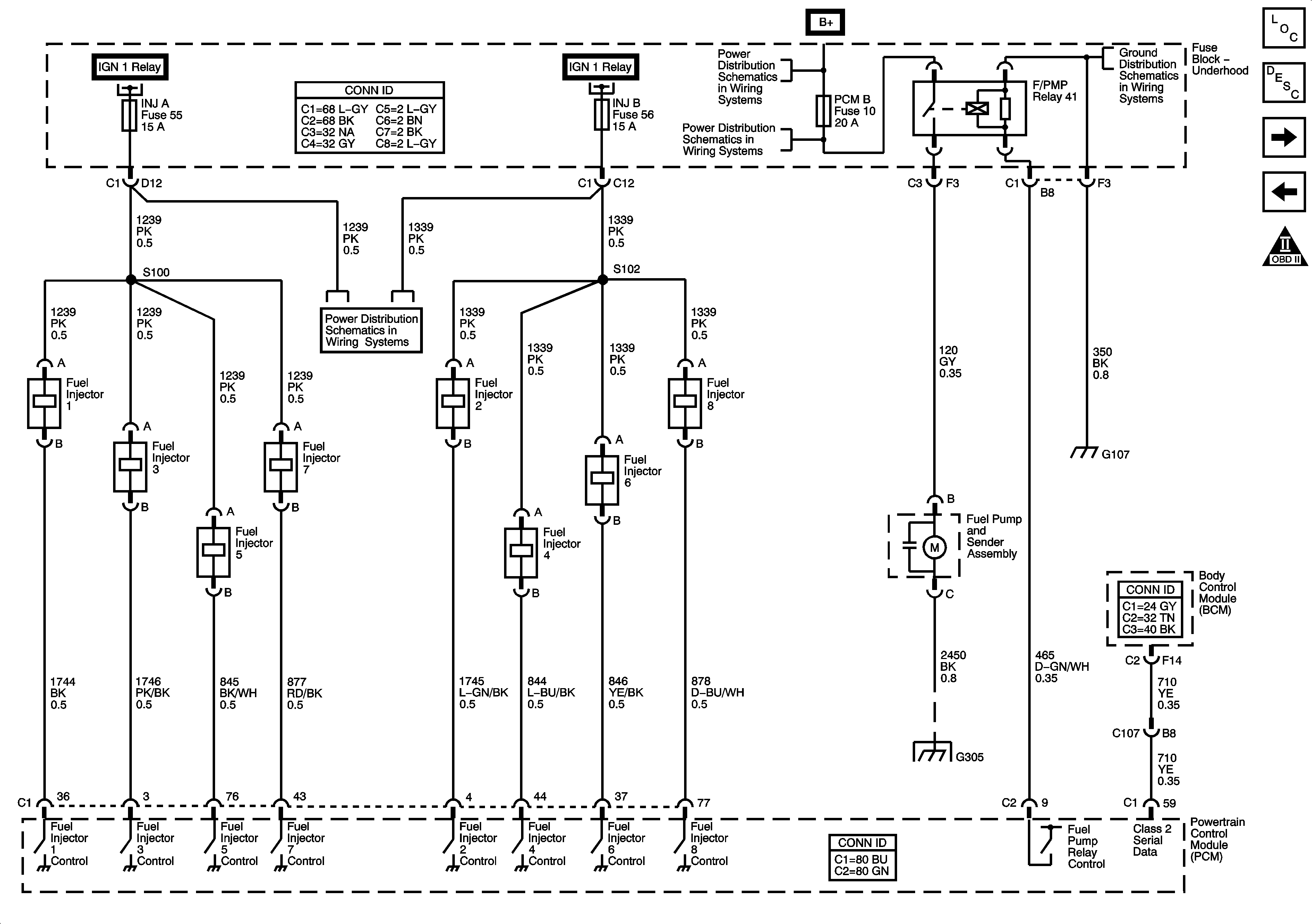
Fuel Controls - Fuel Pump Controls and Fuel Injectors
Ignition Controls - Ignition System Coils 2, 4, 6, 8
OBD II Symbol Description Notice
Figure 10:

Fuel Controls - Fuel Pump Controls and Fuel Injectors


Object Number: 1251406  Size: FS
Master Electrical Component List
Fuel System Description Without Returnless Fuel System
Fuel Controls - EVAP Controls
Ignition Controls - Sensors
OBD II Symbol Description Notice
Fuse Block - Underhood, IGN 1 Relay
B+ Bus - Underhood Fuse Block
G104, G105, and G107
COILS, AIR, EAP, TBC 1, PCM B, LOW HDLP-LT, LOW HDLP-RT, HI HDLP-LT, and HI HDLP-RT Fuses
CANISTER VENT, TAC, INJ A and INJ B Fuses - 5.3L
G201 - 2 of 2, G305, and G306
Figure 11:

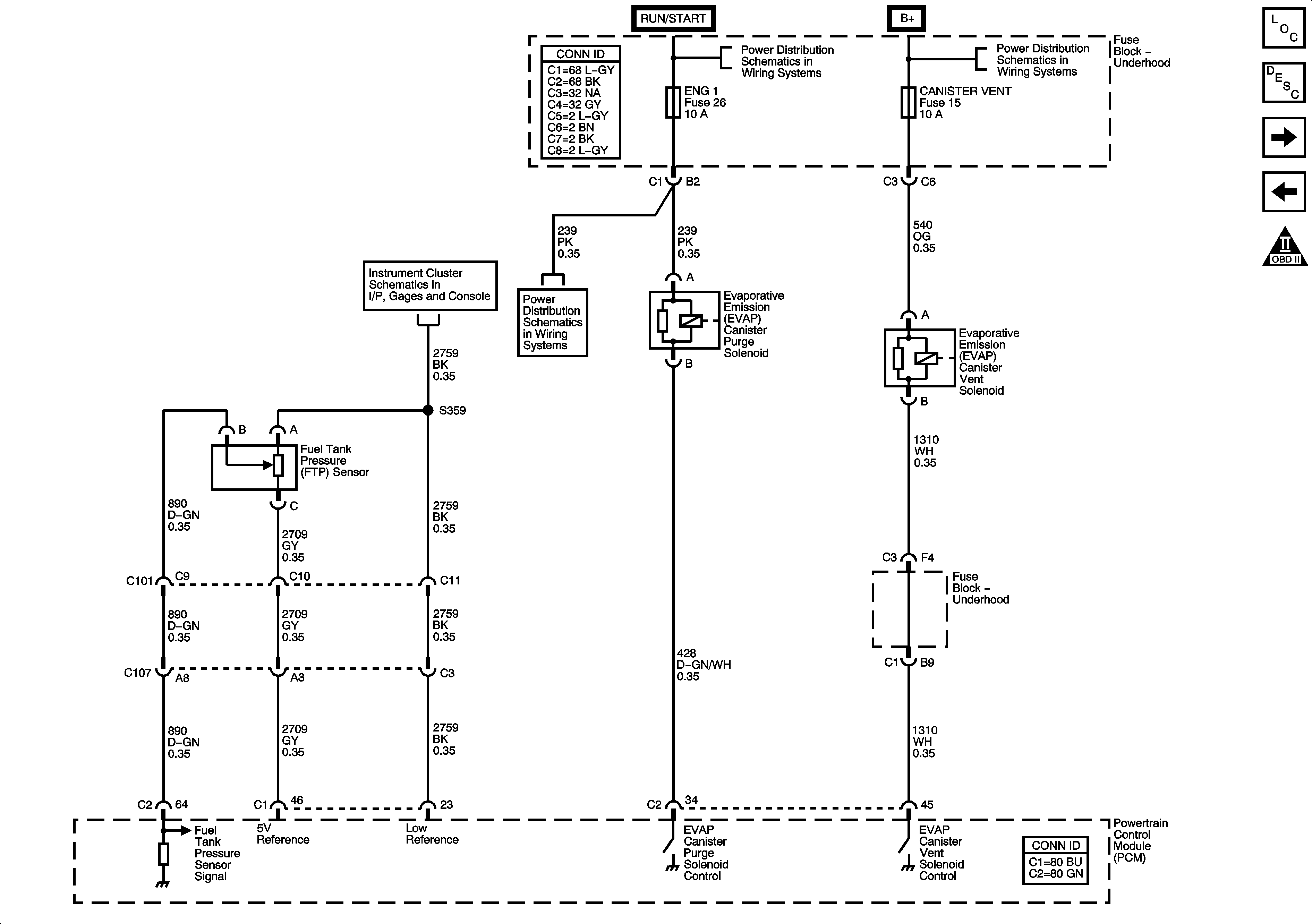
Fuel Controls - EVAP Controls


Object Number: 1251409  Size: FS
Master Electrical Component List
Fuel System Description With Returnless Fuel System
Controlled/Monitored Subsystem References
Fuel Controls - Fuel Pump Controls and Fuel Injectors
OBD II Symbol Description Notice
ACCY/RUN and RUN/START Bus Bars
B+ Bus - Underhood Fuse Block
Fuel Gage
PCM I, O2A, O2B, and ENG I Fuses - 5.3L
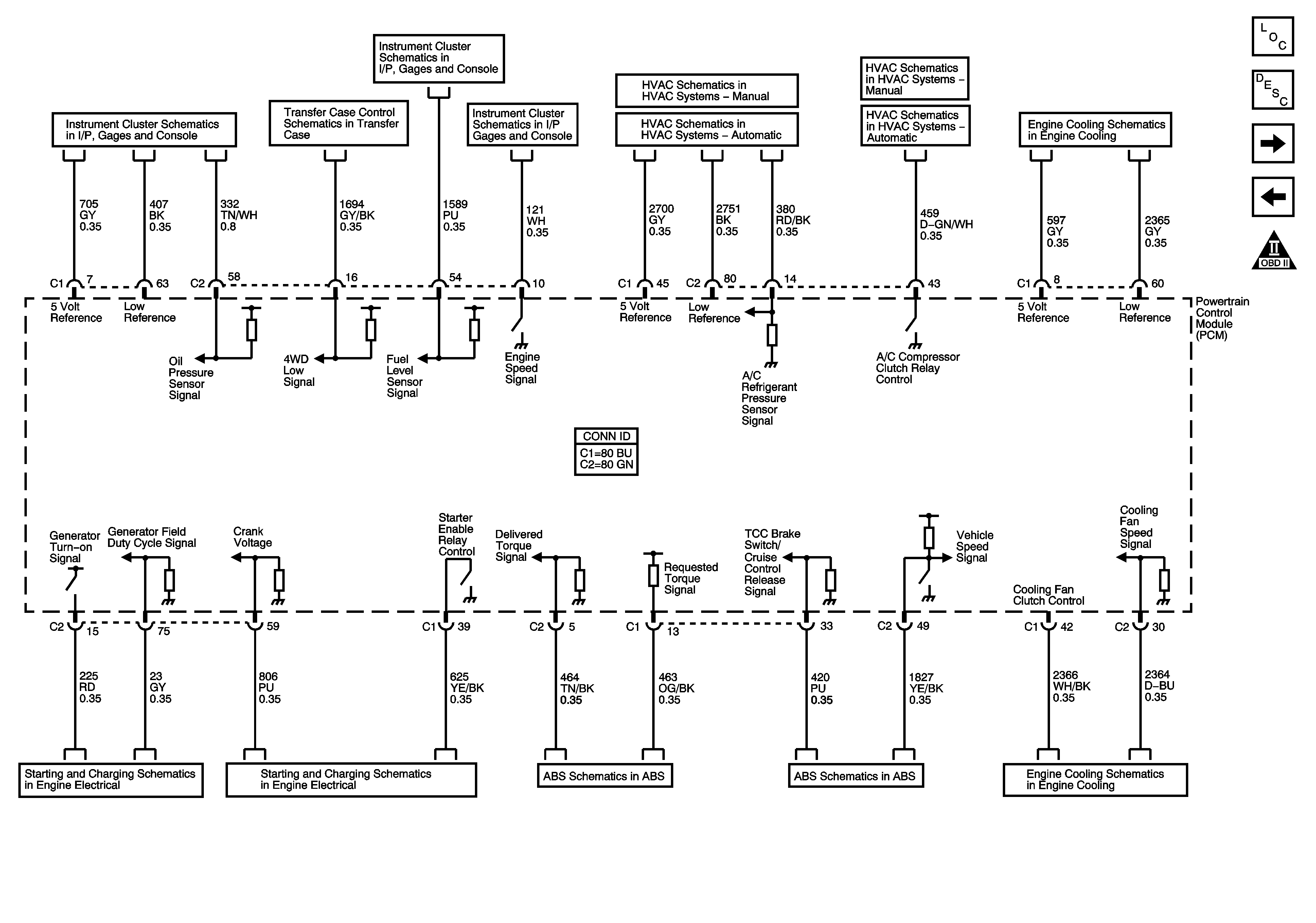
Figure 12:

Controlled/Monitored Subsystem References


Object Number: 1251411  Size: FS
Master Electrical Component List
Powertrain Control Module Description
Transmission Control References - A/T
Fuel Controls - EVAP Controls
OBD II Symbol Description Notice
Gages
Power, Ground, Serial Data, and Transfer Case Encoder Motor
Fuel Gage
Gages
Compressor Controls
Compressor Controls
Compressor Controls
Compressor Controls
04 S/T Isuzu Engine Cooling Schematics
Charging System
Starting System
EBCM Power, Ground, Serial Data, Indicator, and Signal Circuits
04 S/T Isuzu Engine Cooling Schematics
Figure 13:

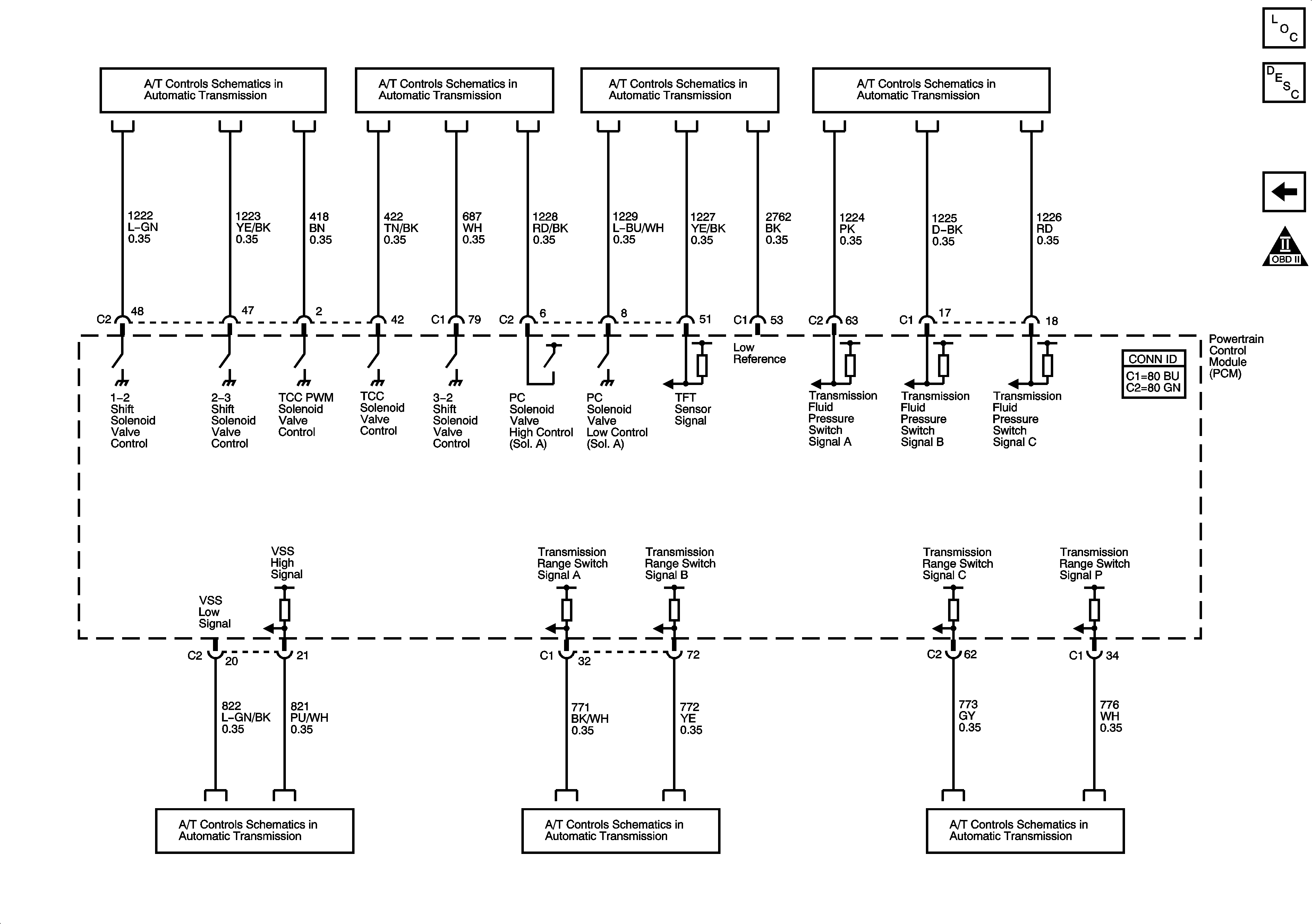
Transmission Control References - A/T


Object Number: 1251412  Size: FS
Master Electrical Component List
Powertrain Control Module Description
Controlled/Monitored Subsystem References
OBD II Symbol Description Notice
Transmission Controls
Stop Lamp Switch Signal and Vehicle Speed Sensor
PNP Switch and Indicator