For 1990-2009 cars only
Removal Procedure
- Remove the intake manifold. Refer to Intake Manifold Replacement .
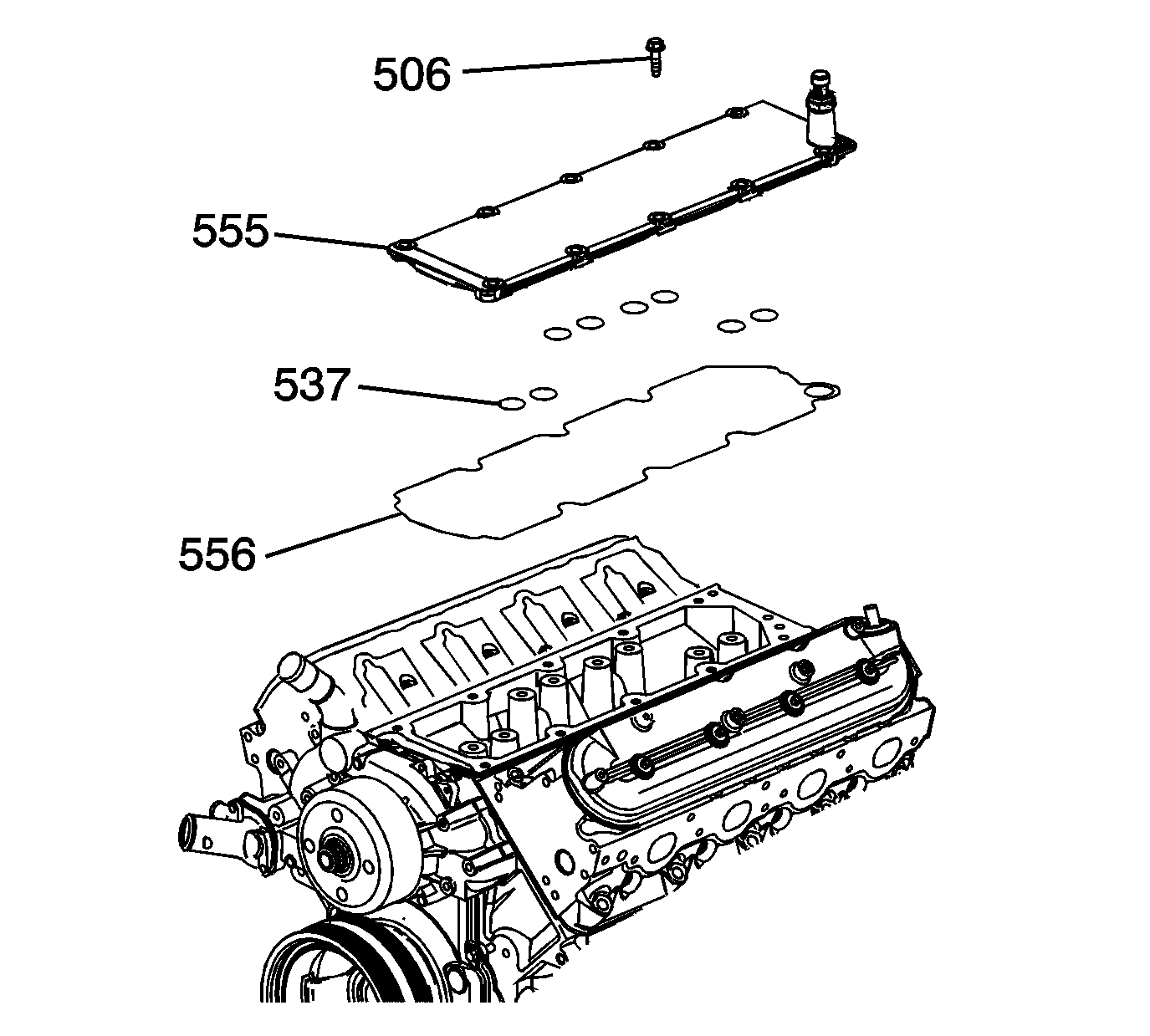
- Remove the valley cover bolts (506).
- Remove the valley cover (555) and gasket (556).
- Remove the O-ring seals (537) from the cover.
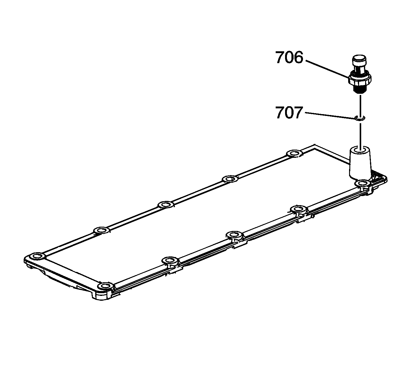
- Remove the oil pressure sensor (706) and washer (707), as required.


Installation Procedure
- Lubricate the O-ring seals with clean engine oil.
- Install the O-ring seals (537) to the cover (555).
- Install the cover (555), gasket (556), and bolts (506).
- Apply sealant to the threads of the sensor. Refer to Adhesives, Fluids, Lubricants, and Sealers for the correct part number.
- Install the oil pressure sensor (706) and sealing washer (707).
- Install the intake manifold. Refer to Intake Manifold Replacement .

Important: All gasket surfaces should be free of oil or other foreign material during assembly.
Notice: Refer to Fastener Notice in the Preface section.
Tighten
Tighten the manifold bolts to 25 N·m (18 lb ft).

Tighten
Tighten the sensor to 35 N·m (26 lb ft).
