For 1990-2009 cars only
Tools Required
J 36607 Ball Joint Separator
Removal Procedure
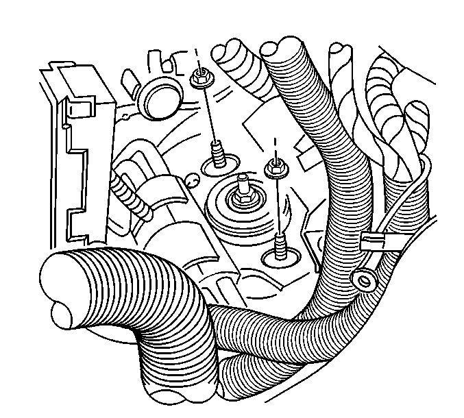
- Remove the shock module upper retaining nuts.
- Raise and support the vehicle. Refer to Lifting and Jacking the Vehicle .
- Remove the tire and wheel. Refer to Tire and Wheel Removal and Installation .
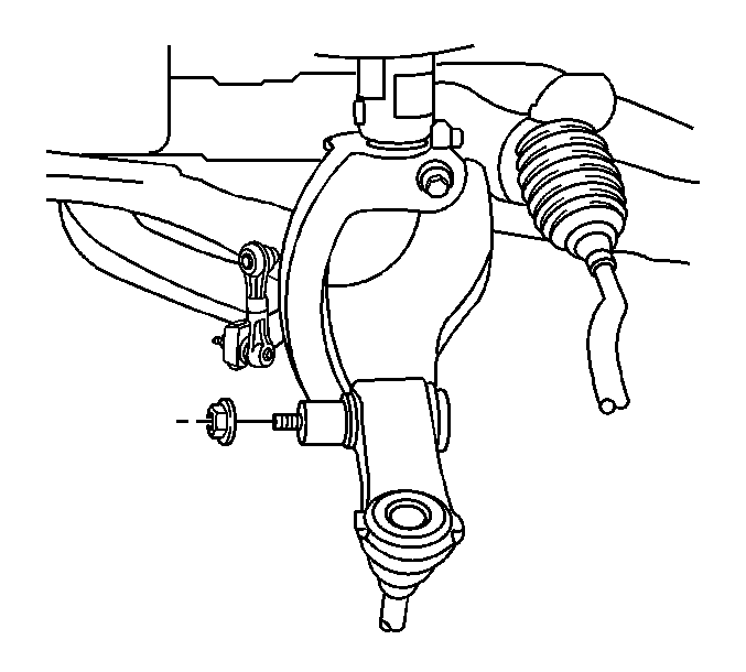
- Loosen the shock module yoke to lower control arm retaining nut.
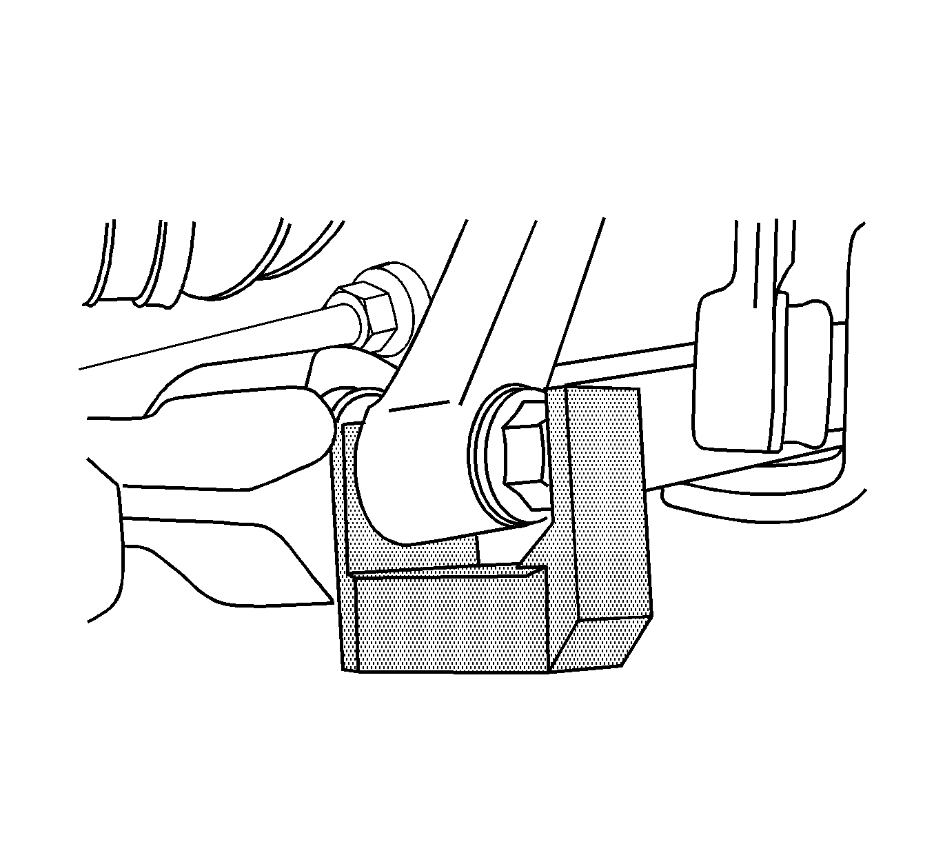
- Remove the shock module yoke from the lower control arm using J 36607 .
- Remove the J 36607 and the shock module yoke to lower control arm retaining nut.
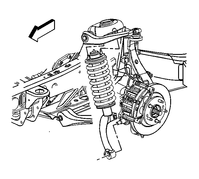
- Remove the shock module from the shock tower and lower control arm.


Notice: Use care when handling the coil springs in order to avoid chipping or scratching the coating. Damage to the coating will result in premature failure of the coil springs.

Pry the yoke away from the control arm to install the J 36607 .

Installation Procedure
- Install the shock module to the shock tower and lower control arm.
- Install the shock module yoke to the lower control arm.
- Lower the vehicle.
- Install the shock module upper retaining nuts.
- Raise the vehicle.
- Install the shock module yoke to lower control arm retaining nut.
- Install the tire and wheel. Refer to Tire and Wheel Removal and Installation .
- Lower the vehicle.

Notice: Refer to Fastener Notice in the Preface section.

Tighten
Tighten the shock module upper retaining nuts to 45 N·m (33 lb ft).

Tighten
Tighten the shock module yoke to lower control arm retaining nut to 111 N·m (82 lb ft).
