For 1990-2009 cars only
Removal Procedure
- Raise and support the vehicle. Refer to Lifting and Jacking the Vehicle in General Information.
- Remove the tire and wheel. Refer to Tire and Wheel Removal and Installation in Tires and Wheels.
- Remove the wheelhouse panel. Refer to Wheelhouse Panel Replacement in Body Rear End.
- Raise and support the rear axle at the designed D - height. Refer to Trim Height Specifications in Suspension General Diagnosis.
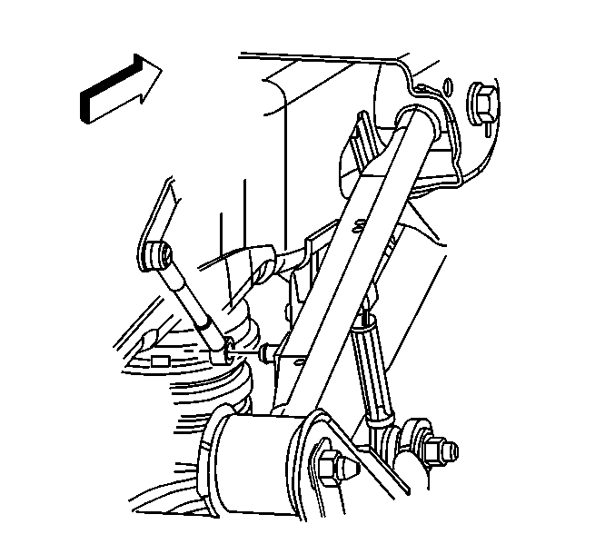
- If equipped with air suspension, remove the air suspension leveling sensor link to the rear axle upper control arm.
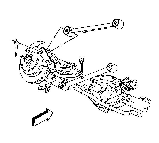
- Remove the rear axle upper control arm to axle mounting bolt and nut.
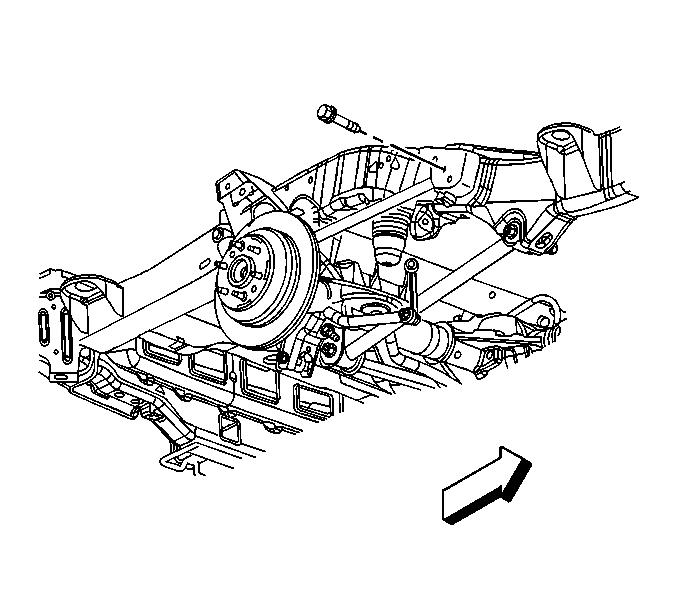
- Remove the rear axle upper control arm to frame mounting bolt.
- Remove the rear axle upper control arm.


Installation Procedure
- Install the rear axle upper control arm.
- Install the rear axle upper control arm to frame mounting bolt.
- Install the rear axle upper control arm to axle mounting nut and bolt.
- If equipped with air suspension, connect the air suspension leveling sensor link to the rear axle upper control arm.
- Remove the rear axle support.
- Install the wheelhouse panel. Refer to Wheelhouse Panel Replacement in Body Rear End.
- Install the tire and wheel. Refer to Tire and Wheel Removal and Installation in Tires and Wheels.
- Lower the vehicle.

Notice: Refer to Fastener Notice in the Preface section.

Tighten
Tighten the rear axle upper control arm mounting bolts to 131 N·m
(97 lb ft).

