Special Tools
Removal Procedure
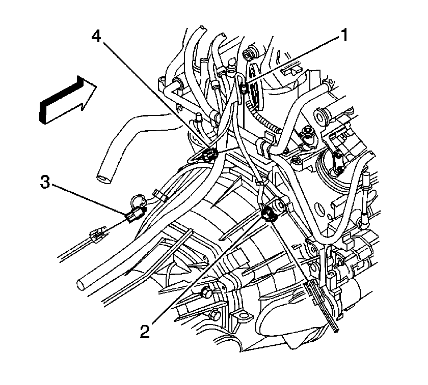
- Remove the hood. Refer to
Hood Replacement.
- Disconnect the negative battery cable. Refer to
Battery Negative Cable Disconnection and Connection.
- Remove the intake manifold sight shield. Refer to
Upper Intake Manifold Sight Shield Replacement.
- Recover the refrigerant. Refer to
Refrigerant Recovery and Recharging.
- Remove the radiator. Refer to
Radiator Replacement.
- Remove the radiator support brace. Refer to
Radiator Support Diagonal Brace Replacement.
- Remove the front differential drive axle, if equipped with 4-wheel drive (4WD). Refer to
Differential Carrier Assembly Replacement.
- Remove the wheel drive shafts, if equipped with 4-wheel drive. Refer to
Wheel Drive Shaft Replacement.
- Remove the intake manifold. Refer to
Intake Manifold Replacement.
- Disconnect the following electrical connectors:
| • | Oil pressure sensor (1) |
| • | Camshaft position (CMP) sensor (4) |
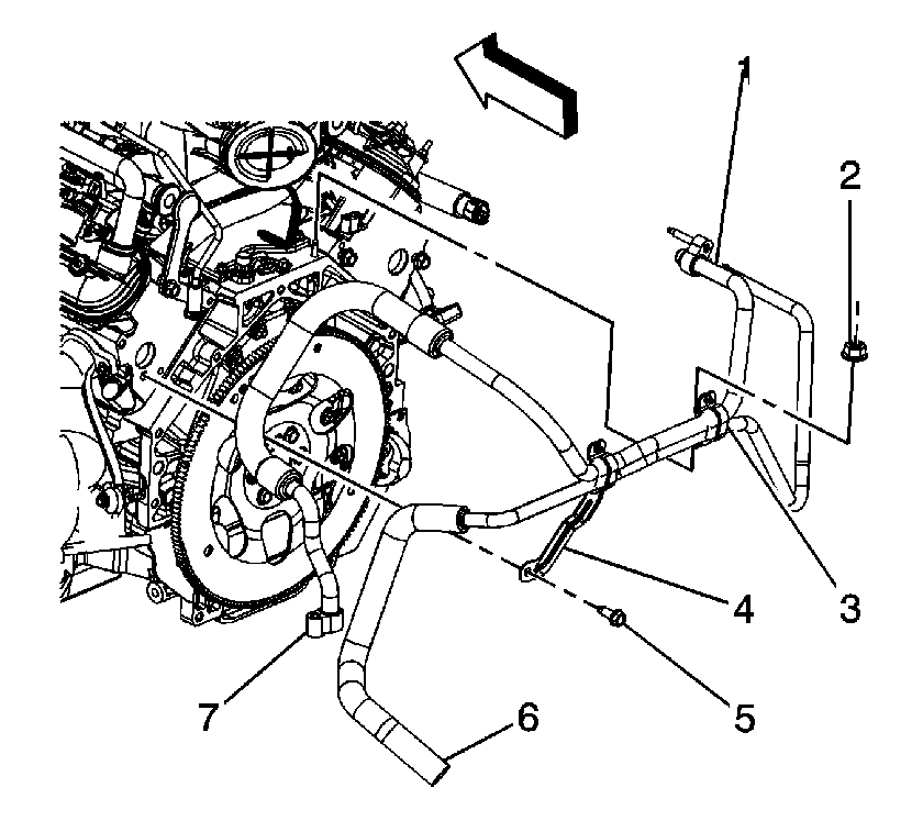
- Remove the air conditioning (A/C) compressor hose. Refer to
Compressor Hose Assembly Replacement.
- Disconnect the rear auxiliary A/C compressor pipe fitting (7).
- Remove the rear auxiliary A/C compressor pipe nut and bolt (2, 5).
- Tie the pipe assembly out of the way.
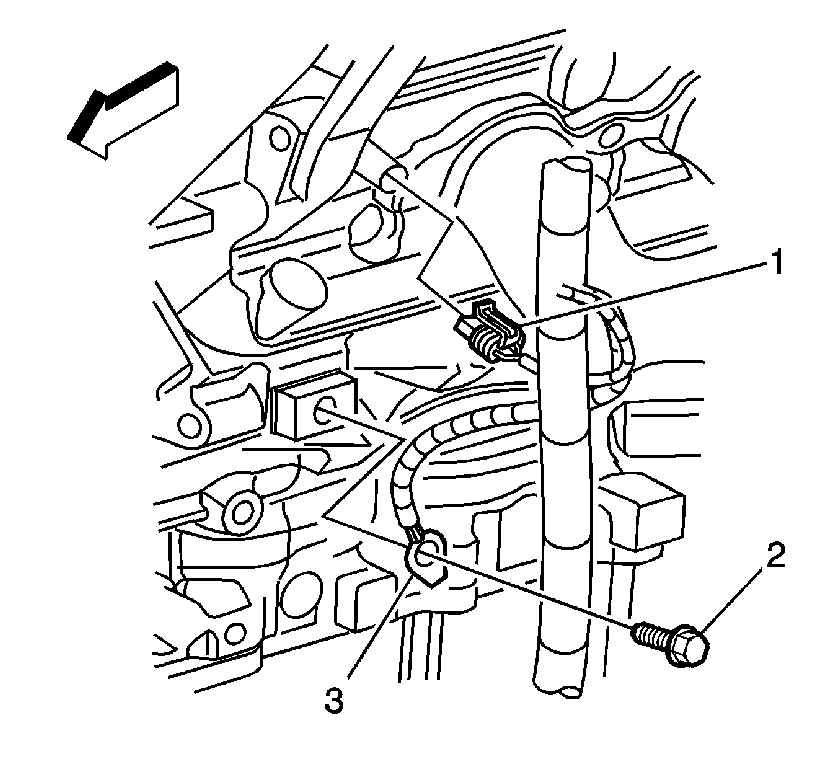
- Disconnect the engine coolant temperature (ECT) sensor (1).
- Remove the ground terminal bolt (2).
- Remove the retaining clips from the brackets.
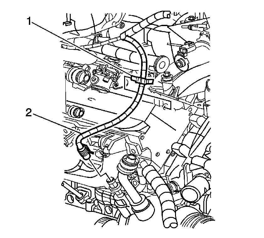
- Disconnect the A/C pressure switch electrical connector (2).
- Remove the retaining clip (1) from the cylinder head.
- Raise and suitably support the vehicle. Refer to
Lifting and Jacking the Vehicle.
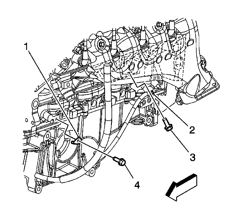
- Remove the ground terminal bolts (2, 4).
- Remove the starter. Refer to
Starter Motor Replacement.
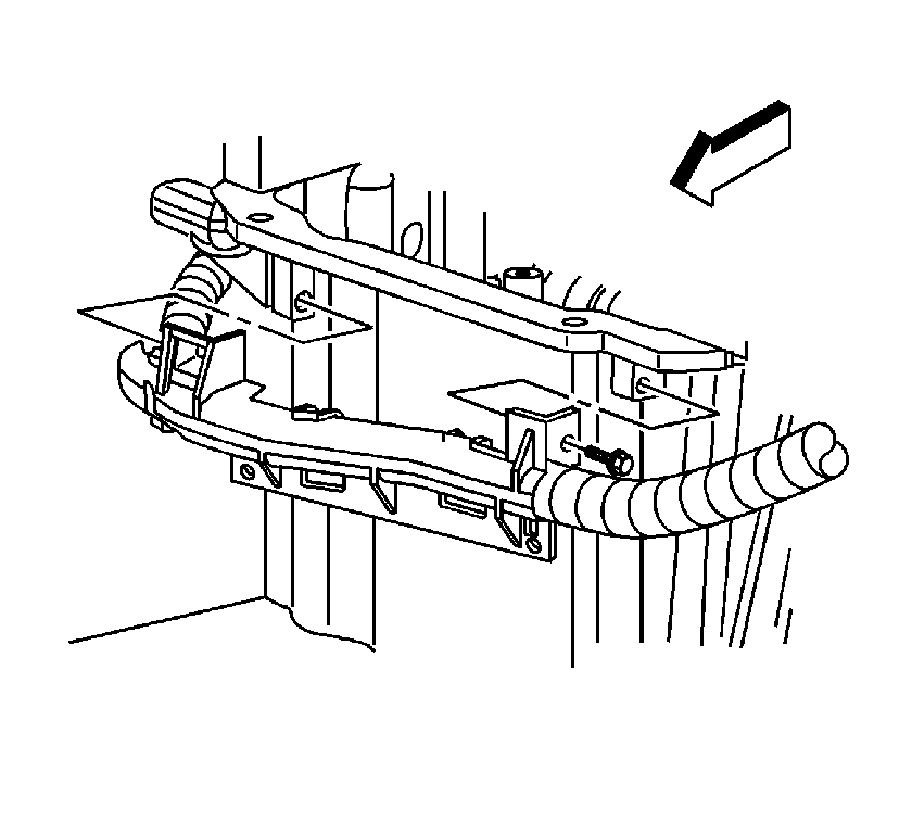
- Remove the battery cable channel bolt.
- Remove the battery cable channel from the oil pan.
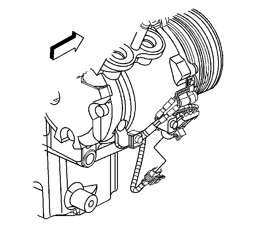
- Disconnect the A/C compressor electrical connector.
- Lower the vehicle.
- Gather all branches of the engine wiring harness and reposition the harness off to the side.
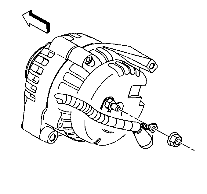
- Remove the generator cable from the generator. Perform the following:
| 28.1. | Slide the boot down revealing the terminal stud. |
| 28.2. | Remove the generator cable nut from the terminal stud. |
| 28.3. | Remove the generator cable. |
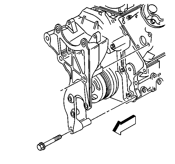
- Remove the generator bracket bolts.
- Position the bracket with generator aside.
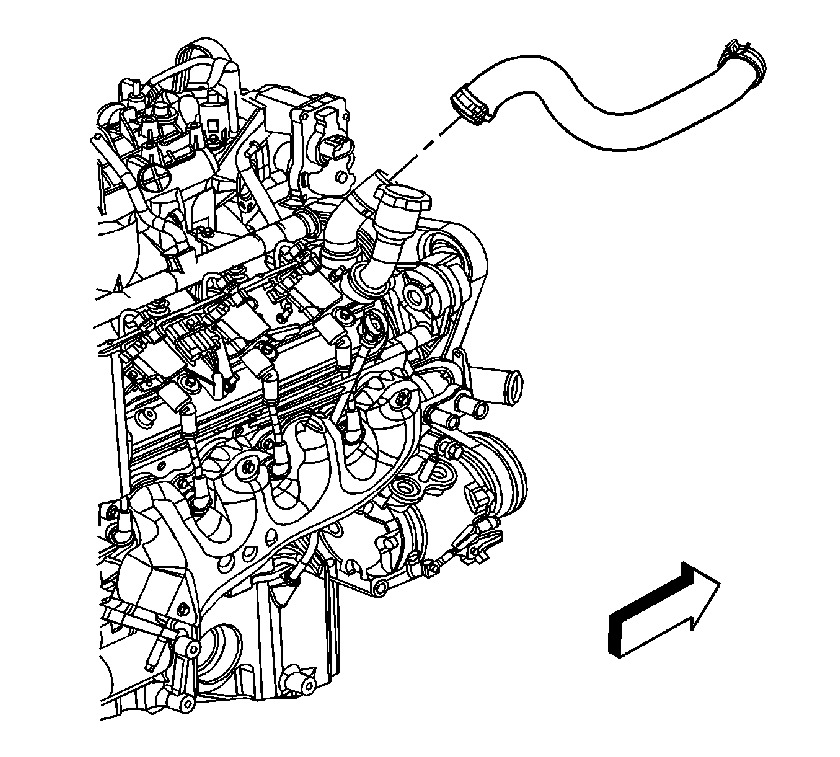
- Using the
J 38185 , remove the inlet hose from the water outlet.
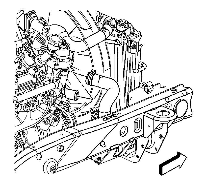
- Using the
J 38185 , remove the outlet hose from the water outlet.
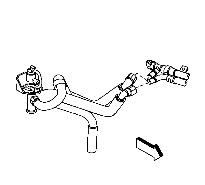
- Disconnect the auxiliary heater inlet and outlet hose/pipe assembly from the heater water shutoff valve pipes.
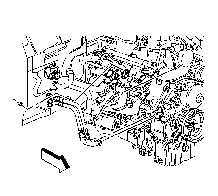
- Using the
J 38185 , remove the auxiliary heater inlet and outlet hoses/pipes from the water pump.
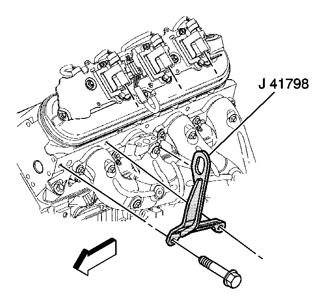
- Remove the ignition coils as required for the proper fit of
J 41798 . Refer to
Ignition Coil Replacement.
Caution: Refer to Fastener Caution in the Preface section.
- Install
J 41798 .
| • | Tighten the M8 bolts to
25 N·m (18 lb ft). |
| • | Tighten the M10 bolts to
50 N·m (37 lb ft). |
- Raise the vehicle.
- Remove the catalytic converter. Refer to
Catalytic Converter Replacement.
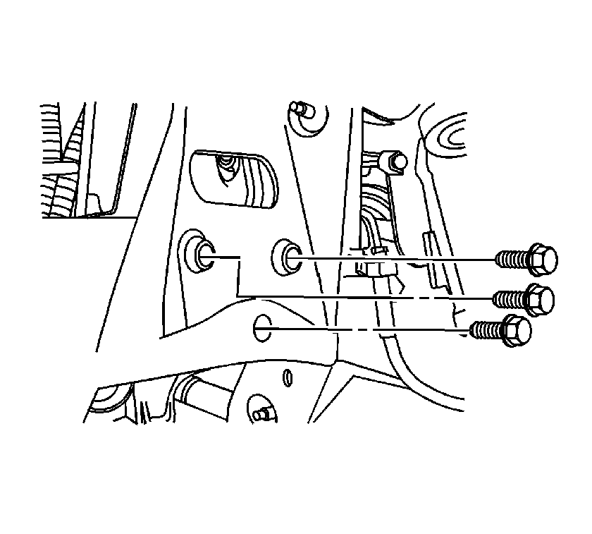
- Remove the 3 bracket bolts from both the right and the left sides of the frame engine mount.
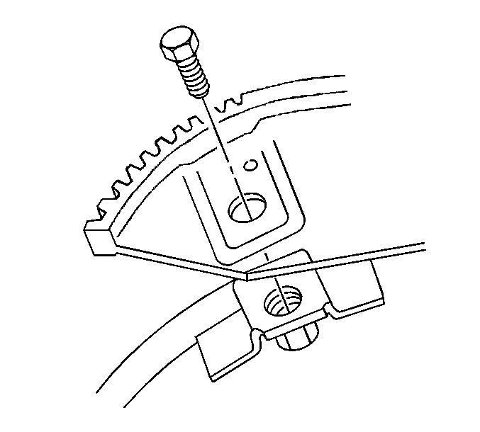
- Remove the torque converter bolts.
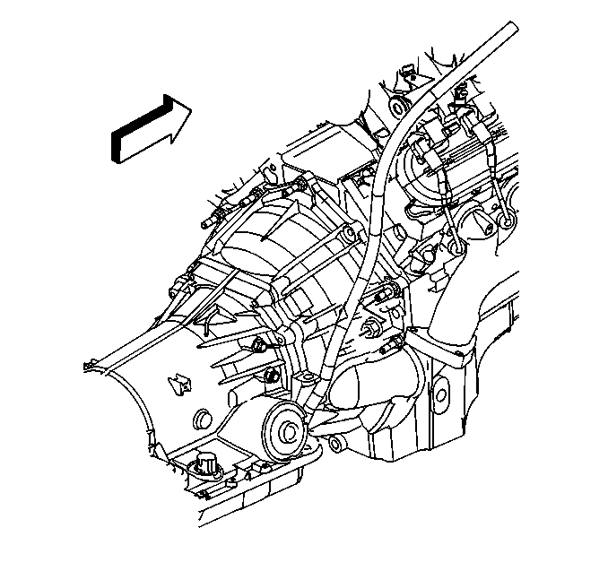
- Remove the transmission oil level indicator tube nut.
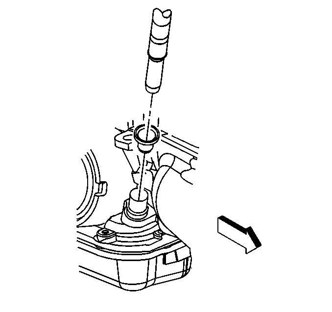
- Remove the transmission oil level indicator tube.
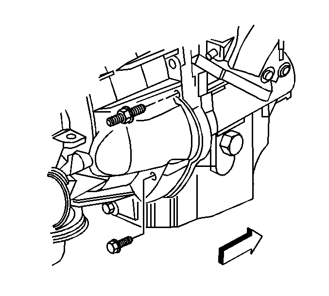
- Remove the transmission bolt and stud on the right side.
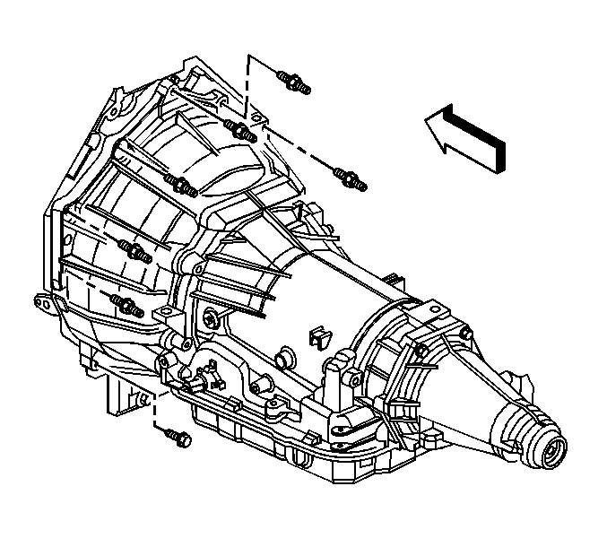
- Remove the lower transmission bolt/studs.
- Lower the vehicle.
- Remove the 3 upper transmission bolts/studs.
- Install an engine hoist to the
J 41798 .
- Install a floor jack under the transmission for support.
- Separate the engine from the transmission.
- Remove the engine.
- Install the engine to an engine stand.
- Install the
J 21366 .
Installation Procedure

- Remove the
J 21366 .
- Install an engine hoist to the
J 41798 .
- Remove the engine from the engine stand.
- Install the engine.
- Mate the engine to the transmission.
- Remove the floor jack from under the transmission for support.
Caution: Refer to Fastener Caution in the Preface section.
- Install the 3 upper transmission bolts/studs and tighten to
50 N·m (37 lb ft).
- Raise the vehicle.
- Install the lower transmission bolt/studs and tighten to
50 N·m (37 lb ft).

- Install the transmission bolt and stud on the right side and tighten to
50 N·m (37 lb ft).

- Install the transmission oil level indicator tube.

- Install the transmission oil level indicator tube nut and tighten to
10 N·m (89 lb ft).

- Install the torque converter bolts and tighten to
60 N·m (44 lb ft).

- Install the 3 bracket bolts to both the right and the left sides of the frame engine mount and tighten to
50 N·m (37 lb ft)
- Install the catalytic converter. Refer to
Catalytic Converter Replacement.
- Lower the vehicle.

- Remove
J 41798 .
- Install the ignition coils, as required. Refer to
Ignition Coil Replacement. Tighten the bolts to
8 N·m (71 lb in).

- Install the auxiliary heater inlet and outlet hoses/pipes to the water pump using the
J 38185 .

- Connect the auxiliary heater inlet and outlet hose/pipe assembly to the heater water shutoff valve pipes.

- Install the outlet hose to the water outlet using the
J 38185 .

- Install the inlet hose to the water outlet using the
J 38185 .

- Position the bracket with generator to the engine.
- Install the generator bracket bolts and tighten to
50 N·m (37 lb ft).

- Install the generator cable to the generator, perform the following procedure:
| 25.1. | Install the generator cable. |
| 25.2. | Install the generator cable nut to the terminal stud and tighten to
9 N·m (80 lb in). |
| 25.3. | Slide the boot down covering the terminal stud. |

- Gather all branches of the engine wiring harness and position the harness over the engine.
- Raise the vehicle.
- Connect the A/C compressor electrical connector.

- Install the battery cable channel to the oil pan.
- Install the battery cable channel bolt and tighten to
12 N·m (106 lb in).

- Install the starter. Refer to
Starter Motor Replacement.
- Install the ground terminal bolts (2, 4) and tighten to
25 N·m (18 lb ft).
- Lower the vehicle.

- Install the retaining clip (1) to the cylinder head.
- Connect the A/C pressure switch electrical connector (2).

- Install the retaining clips to the brackets.
- Install the ground terminal bolt (2) and tighten to
25 N·m (18 lb ft).
- Connect the ECT sensor (1).

- Install the rear auxiliary A/C compressor pipe nut and bolt (2, 5) and tighten to
20 N·m (15 lb ft).
- Connect the rear auxiliary A/C compressor pipe fitting (7). Tighten the nut to
16 N·m (12 lb ft).
- Install the A/C compressor hose. Refer to
Compressor Hose Assembly Replacement.

- Connect the following electrical connectors:
| • | Oil pressure sensor (1) |
| • | Camshaft position (CMP) sensor (4) |
- Install the intake manifold. Refer to
Intake Manifold Replacement.
- Install the wheel drive shafts. Refer to
Wheel Drive Shaft Replacement.
- Install the front differential drive axle, if equipped with 4WD. Refer to
Differential Carrier Assembly Replacement.
- Install the radiator support brace. Refer to
Radiator Support Diagonal Brace Replacement.
- Install the radiator. Refer to
Radiator Replacement.
- Recharge the refrigerant. Refer to
Refrigerant Recovery and Recharging.
- Connect the negative battery cable. Refer to
Battery Negative Cable Disconnection and Connection.
- Prelube the engine. Refer to
Engine Prelubing.
- Perform the CKP system variation learn procedure. Refer to
Crankshaft Position System Variation Learn.
- Install the hood. Refer to
Hood Replacement.
Note: After an overhaul, the engine should be tested. Use the following procedure after the engine is installed in the vehicle.
- Test the vehicle using the following procedure:
| 53.1. | Disable the ignition system. |
| 53.2. | Crank the engine several times. Listen for any unusual noises or evidence that parts are binding. |
| 53.3. | Enable the ignition system. |
| 53.4. | Start the engine and listen for unusual noises. |
| 53.5. | Check the vehicle oil pressure gauge or light and confirm that the engine has acceptable oil pressure. |
| 53.6. | Run the engine speed at about 1,000 RPM until the engine has reached normal operating temperature. |
| 53.7. | Inspect for fuel, oil and/or coolant leaks while the engine is running. |
- Install the intake manifold sight shield. Refer to
Upper Intake Manifold Sight Shield Replacement.


