For 1990-2009 cars only
Removal Procedure
- Raise and support the vehicle. Refer to Lifting and Jacking the Vehicle.
- Remove the tire and wheel assembly. Refer to Tire and Wheel Removal and Installation.
- Remove any dirt or debris from the threads of the stabilizer link bolt.
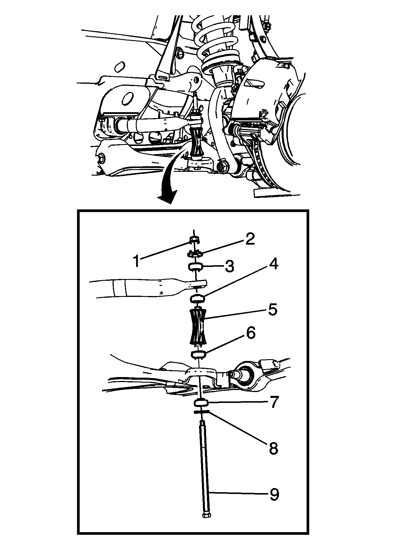
- Use the proper size wrench or socket to hold the stabilizer bolt while removing the stabilizer shaft nut (1).
- Remove the washer (2) and the insulator (3) from the stabilizer shaft link bolt (9).
- Remove the stabilizer shaft link bolt (9), washer (8) and the insulator (7).
- Remove the insulators (4) (6), spacer (5).

Installation Procedure
- Install the washer (8) and the insulator (7) on the stabilizer shaft link bolt (9).
- Position the insulators (4) (6), spacer (5) between the stabilizer shaft and the lower control arm.
- Install the stabilizer shaft link bolt (9), washer (8) and the insulator (7).
- Install the insulator (3) and the washer (2).
- Install the stabilizer shaft link nut and tighten to 23 N·m (17 lb ft).
- Install the tire and wheel assembly. Refer to Tire and Wheel Removal and Installation.
- Remove the support and lower the vehicle.

Note: When installing the spacer (5) and the insulators (3), (4), (6) and (7), ensure that the insulators are properly seated in the stabilizer shaft and the lower control arm.
Note: Use the stabilizer shaft bolt (9) to align the spacer (5) and the insulators (3), (4) , (6) and (7) during the installation of the stabilizer shaft bolt (9).
Caution: Refer to Fastener Caution in the Preface section.
