Special Tools
| • | J 41816 Crankshaft Balancer Remover |
| • | J 41665 Crankshaft Balancer and Sprocket Installer |
Removal Procedure
- Remove the accessory drive belt. Refer to
Drive Belt Replacement - Accessory.
- Remove the air conditioning (A/C) drive belt, if equipped. Refer to
Air Conditioning Compressor Belt Replacement.
- Remove the fan shroud. Refer to
Cooling Fan and Shroud Replacement.
- Remove the starter motor. Refer to
Starter Motor Replacement.
Caution: Refer to Fastener Caution in the Preface section.
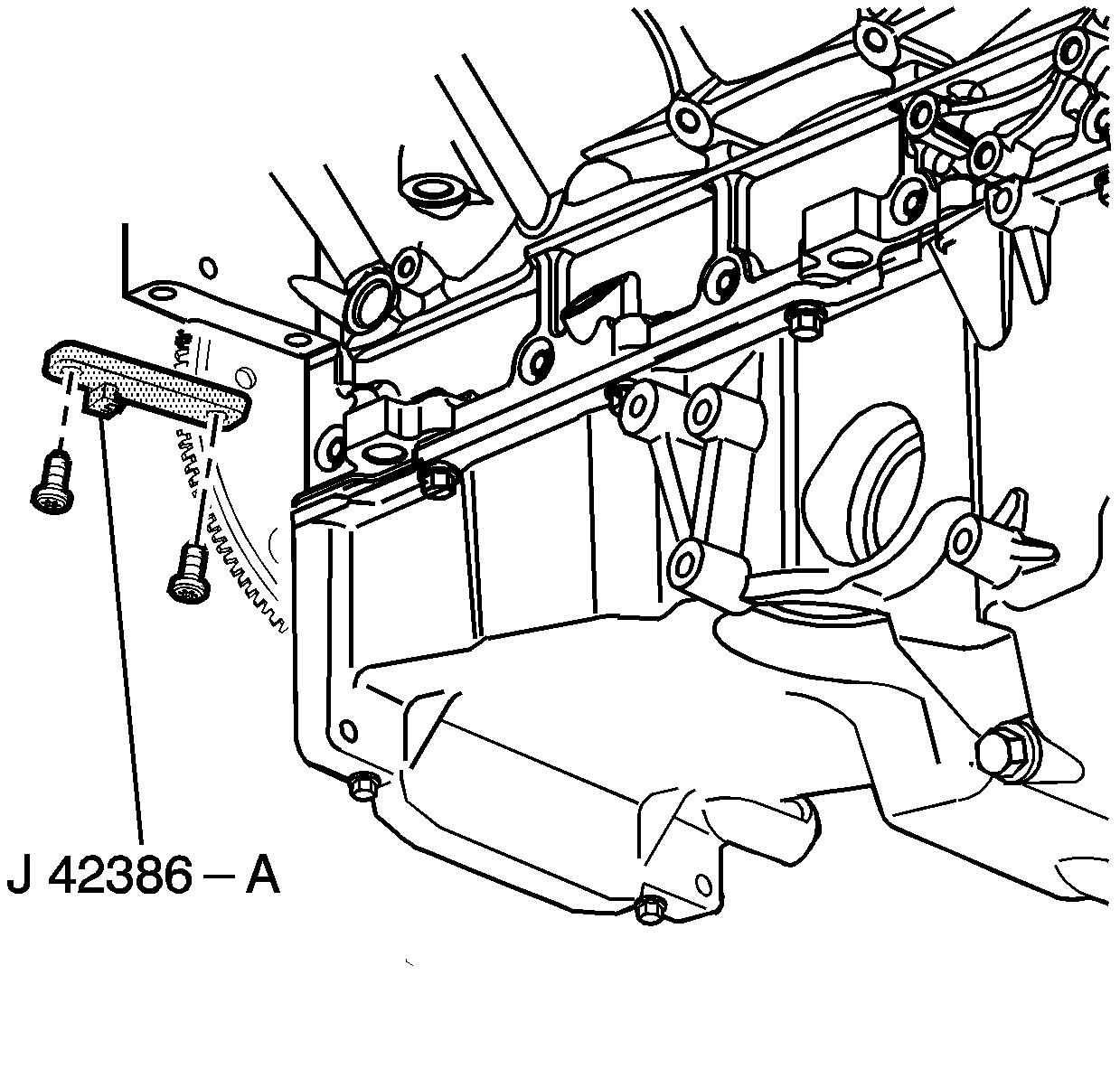
Note:
| • | Ensure that the teeth of
J 42386-A mesh with the teeth of the engine flywheel. |
| • | The crankshaft balancer is balanced as an individual component. It is not necessary to mark the balancer prior to removal. |
- Install
J 42386-A and bolts.
Use one M10-1.5 x 120 mm and one M10-1.5 x 45 mm bolt for proper tool operation. Tighten
J 42386-A bolts to
50 N·m
(37 lb ft).
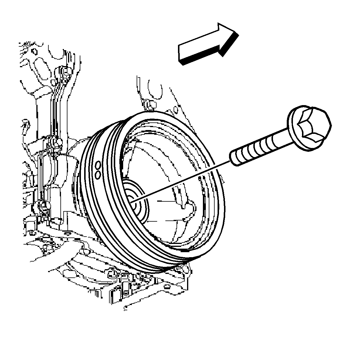
- Remove the crankshaft balancer bolt.
Do not discard the crankshaft balancer bolt. The balancer bolt will be used during the balancer installation procedure.
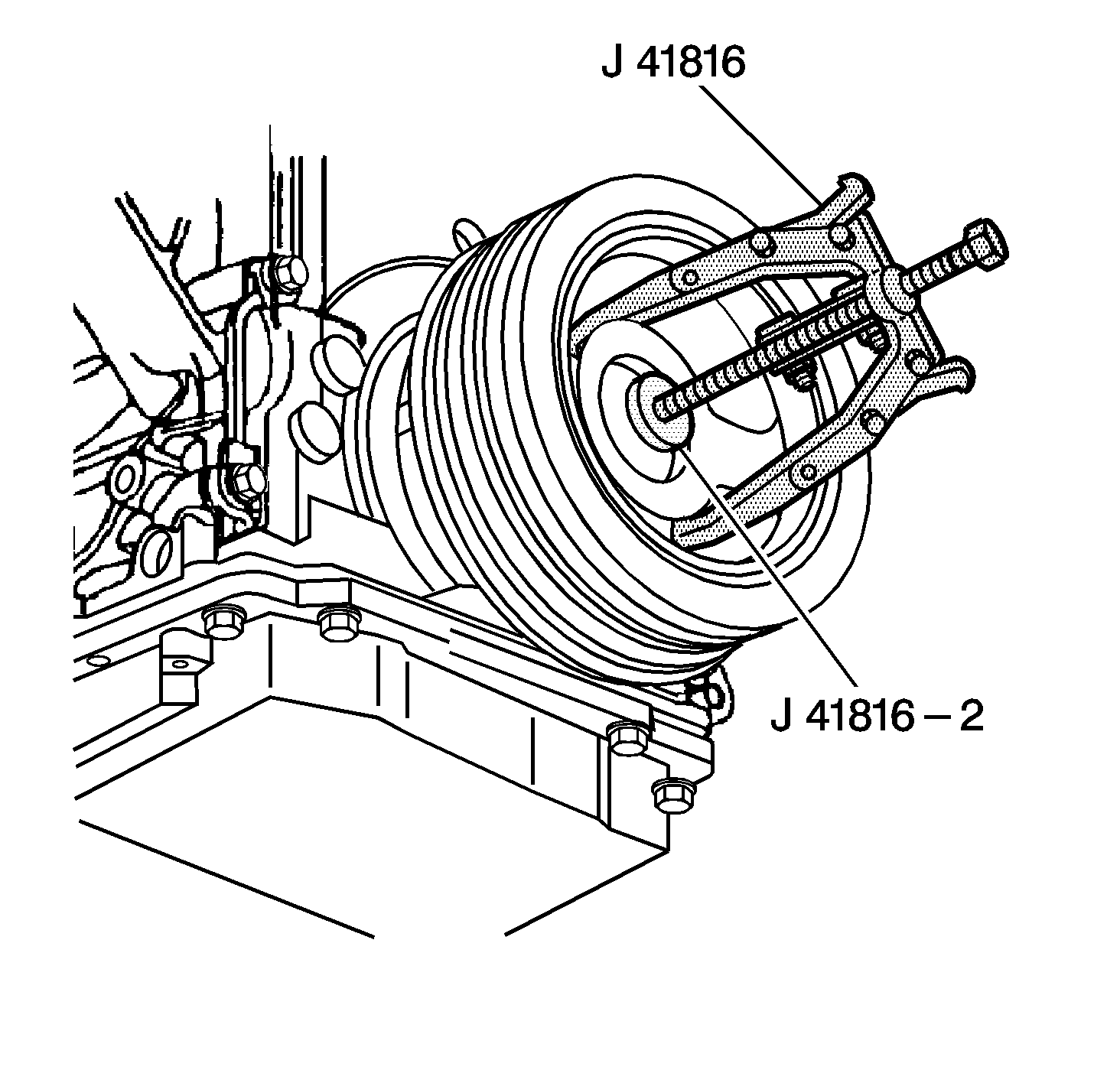
- Use
J 41816 and
J 41816-2 in order to remove the crankshaft balancer.
- Remove
J 41816 and
J 41816-2 from the crankshaft balancer.
- Clean and inspect the crankshaft balancer. Refer to
Crankshaft Balancer Cleaning and Inspection.
Installation Procedure

Note:
| • | Ensure that the teeth of
J 42386-A mesh with the teeth of the engine flywheel. |
| • | The used crankshaft balancer bolt will be used only during the first pass of the balancer installation procedure. Install a NEW bolt and tighten as described in the second pass of the balancer bolt tightening procedure. |
| • | The crankshaft balancer installation and bolt tightening involves a 4-stage tightening process. The first pass ensures that the balancer is installed completely onto the crankshaft. The second, third, and forth passes tighten the new bolt to the
proper torque. |
Note: Position the balancer onto the end of the crankshaft as straight as possible prior to tool installation.
- Install the crankshaft balancer onto the end of the crankshaft.
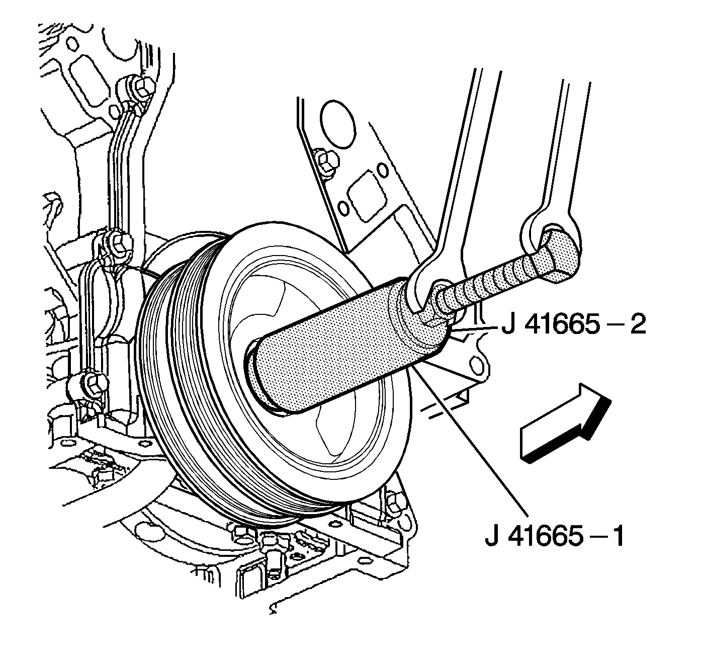
- Use
J 41665 in order to install the crankshaft balancer.
| 2.1. | Assemble the threaded rod, nut, washer, and installer. |
Insert the smaller end of the installer into the front of the balancer.
| 2.2. | Use a wrench and hold the hex end of the threaded rod. |
| 2.3. | Use a second wrench and rotate the installation tool nut clockwise until the balancer is started onto the crankshaft. |
| 2.4. | Remove the tool and reverse the installation tool. |
Position the larger end of the installer against the front of the balancer.
| 2.5. | Use a wrench and hold the hex end of the threaded rod. |
| 2.6. | Use a second wrench and rotate the installation tool nut clockwise until the balancer is installed onto the crankshaft. |
| 2.7. | Remove the balancer installation tool. |
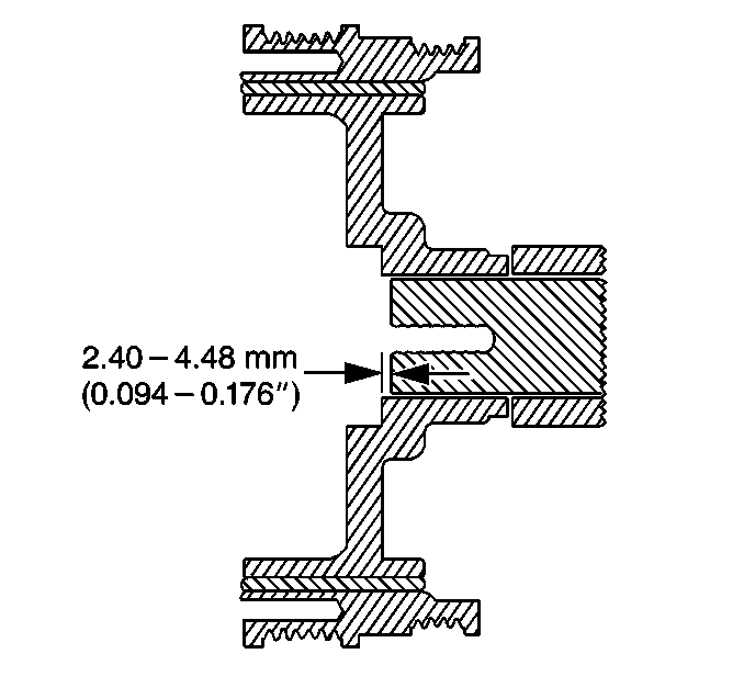
- Install the used crankshaft balancer bolt. Tighten the USED bolt to
330 N·m (240 lb ft).
- Remove the used crankshaft balancer bolt.
Note: Recess the nose of the crankshaft 2.4-4.48 mm (0.094-0.176 in) into the balancer bore.
- Measure for a correctly installed balancer.
If the balancer is not installed to the proper dimensions, install
J 41665 and repeat the installation procedure.
- Install a NEW crankshaft balancer bolt.
| 6.1. | Tighten the bolt a first pass to
50 N·m (37 lb ft). |
| 6.2. | Tighten the bolt a final pass to 140 degrees using
J 45059 . |
- Remove
J 42386-A and bolts.
- Install the starter motor. Refer to
Starter Motor Replacement.
- Install the fan shroud. Refer to
Cooling Fan and Shroud Replacement.
- Install the A/C drive belt, if equipped. Refer to
Air Conditioning Compressor Belt Replacement.
- Install the accessory drive belt. Refer to
Drive Belt Replacement - Accessory.
- Perform the crankshaft position (CKP) system variation learn procedure. Refer to
Crankshaft Position System Variation Learn.


