Special Tools
| • | J 8087 Cylinder Bore Gage |
For equivalent regional tools, refer to
Special Tools

Note: Use care when handling the crankshaft. Avoid damaging the crankshaft reluctor wheel. Nicks, burrs or other damage to the teeth may effect the On-board Diagnostics (OBD) II system performance.
- Clean the crankshaft of all elements.
- Inspect the crankshaft oil passages for obstructions.
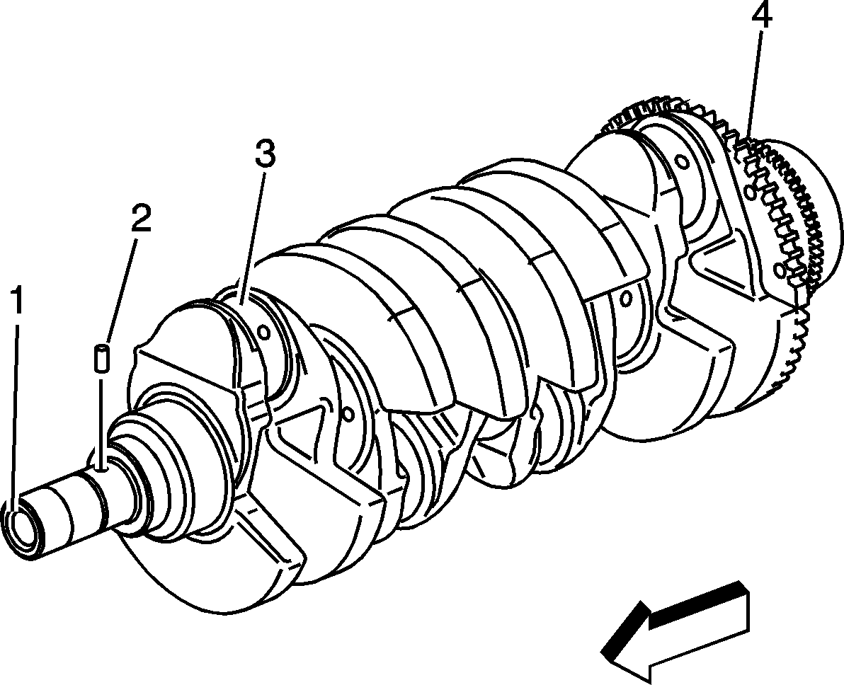
- Inspect the crankshaft for the following conditions:
| • | Worn crankshaft pin (2) |
| • | Wear without any grooves or scratches (3) |
| • | Pitting or embedded bearing material (3) |
| • | Overheating - discoloration (3) |

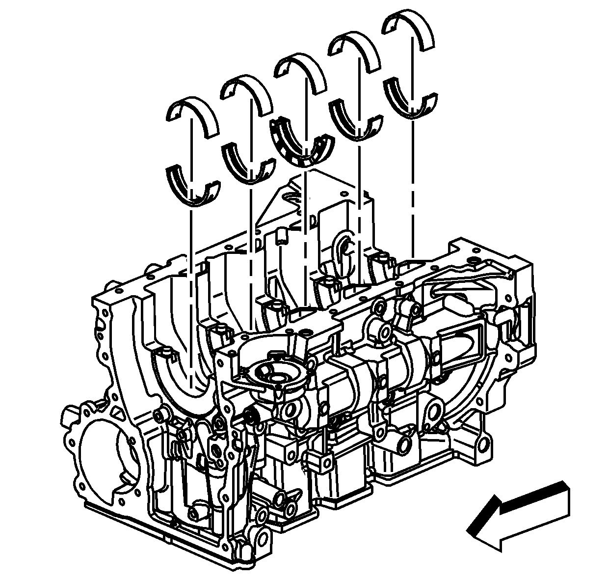
- Inspect the corresponding crankshaft bearing inserts for embedded material and determine the source of the material.
Note: If cracks, severe gouges or burned spots are found, replace the crankshaft. Remove slight roughness using a fine polishing cloth soaked in clean engine oil. Remove any burrs using a fine oil stone.
- Inspect the outer surfaces of the crankshaft bearings for the following conditions:
| • | Wear -- surface wear indicates either movement of the insert or high spots in the surrounding material (spot wear) |
| • | Overheating or discoloration |
| • | Looseness or rotation indicated by flattened tangs and wear grooves |
Note: Note the location of the crankshaft main bearing high spots. If the spots are not in line, the crankshaft is bent. Replace the crankshaft.
- Inspect the crankshaft main bearings for craters or pockets. Flattened sections on the crankshaft bearing halves also indicate fatigue.
- Inspect the thrust surfaces of the main thrust bearing for the following conditions:
| • | Grooving -- Grooves are caused by irregularities of the crankshaft thrust surface. |
- Inspect the crankshaft bearings for excessive scoring or discoloration.
- Inspect the crankshaft bearings for dirt or imbedded debris.
- Inspect the crankshaft bearings for improper seating indicated by bright, polished sections.
- Inspect the crankshaft bearings for uneven side-to-side wear. This may indicate a bent crankshaft or a tapered bearing journal.
Note: If crankshaft bearing failure is due to conditions other than normal wear, investigate the cause of the condition. Inspect the crankshaft or connecting rod bearing bores.
- Inspect the connecting rod bearing bores using the following procedure:
| 12.1. | Tighten the connecting rod bearing cap to specification. |
| 12.2. | Use
J 8087 gage
to measure the bearing bore for taper and out-of-round. Record the readings. |
| 12.3. | No taper or out-of-round should exist. |

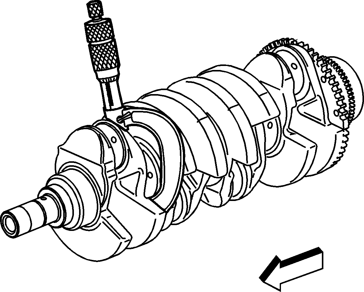
- Measure the crankshaft bearing journal diameter with a micrometer in several places,
90 degrees apart. Average the measurements.

- Measure the crankshaft bearing journal taper and runout.
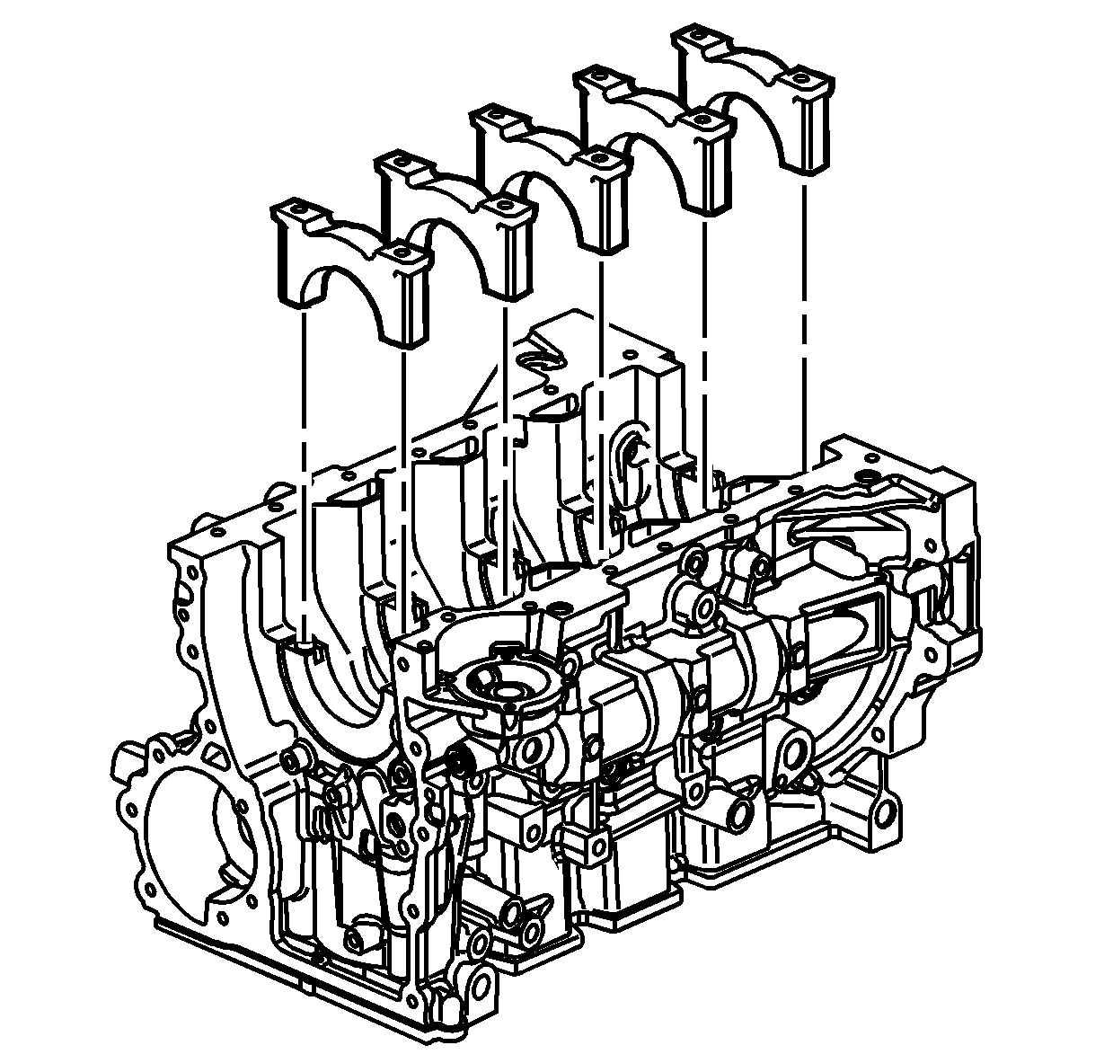
- Install the crankshaft bearing caps.
- Install the crankshaft main bearing cap stiffener.
Caution: Refer to Fastener Caution in the Preface section.
- Install the crankshaft bearing cap bolts.
| 17.1. | Tighten the crankshaft bearing cap bolts to
25 N·m (18 lb ft). |
| 17.2. | Use
J 45059 meter
to tighten the crankshaft bearing cap bolts an additional
180 degrees. |
- Measure the crankshaft main bearing inside diameter with an inside micrometer.
- Measure the connecting rod inside diameter in the same direction as the length of the rod with an inside micrometer.
- If the specified clearances cannot be met, the crankshaft, connecting rods, or block may need to be replaced.


