GM Service Manual Online
For 1990-2009 cars only
Makes
🢒
Isuzu
🢒
2007
🢒
I-370
🢒
Diagnostic Navigation
🢒
Vehicle Diagnostic Information
🢒 Starting and Charging Schematics
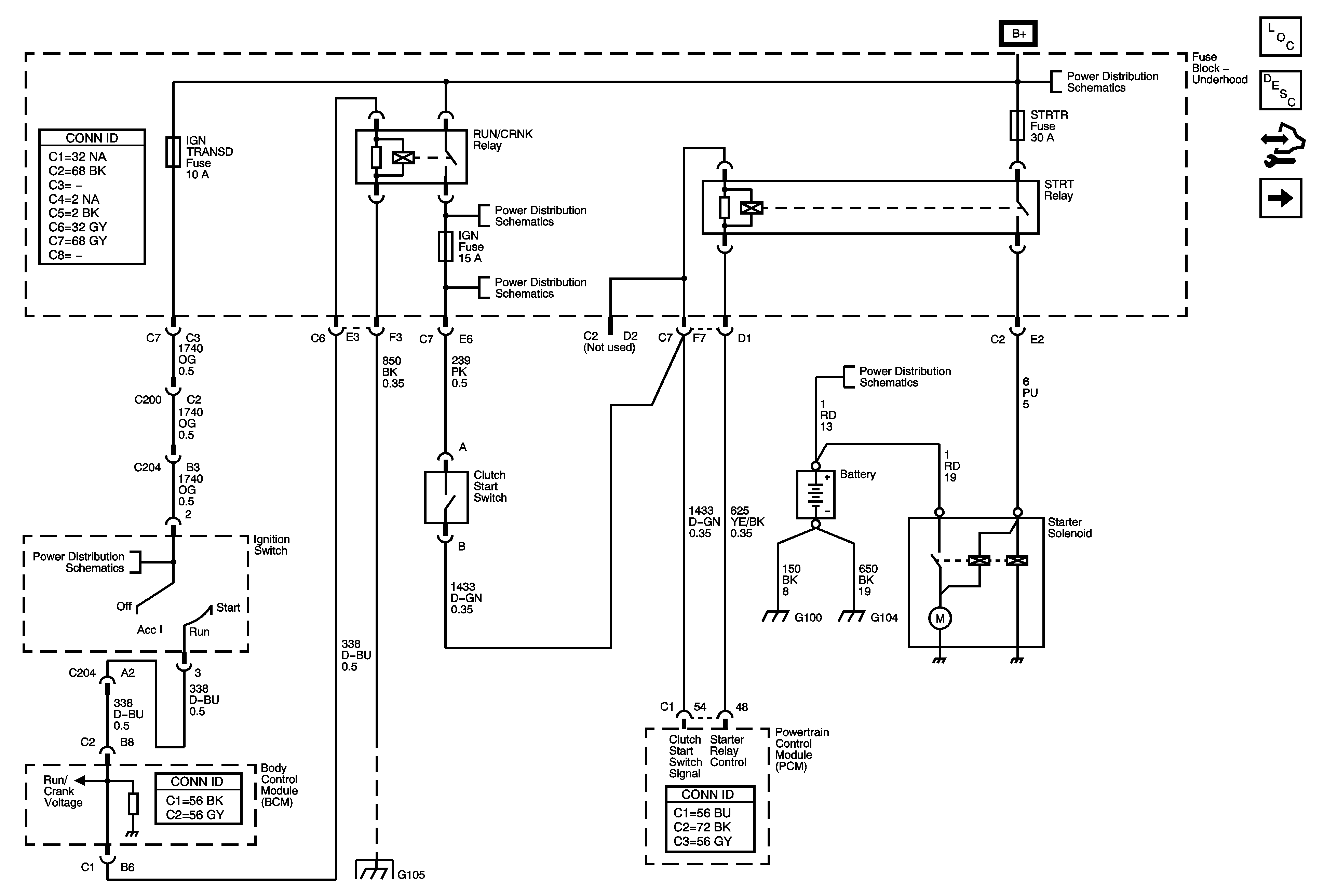
Figure
1:
Starting System - MA5
Master Electrical Component List
Starting System Description and Operation
Body Control Module Programming and Setup
Starting System - M30
B+ Bus - Underhood Fuse Block
RUN/CRANK RELAY BUS - 2 of 3, ABS, BACKUP, and IGN Fuses
B+ Bus - Underhood Fuse Block
Ignition Switch and IGN TRANS D Fuse
Splice Pack SP105 and G105 - 1 of 2
Figure
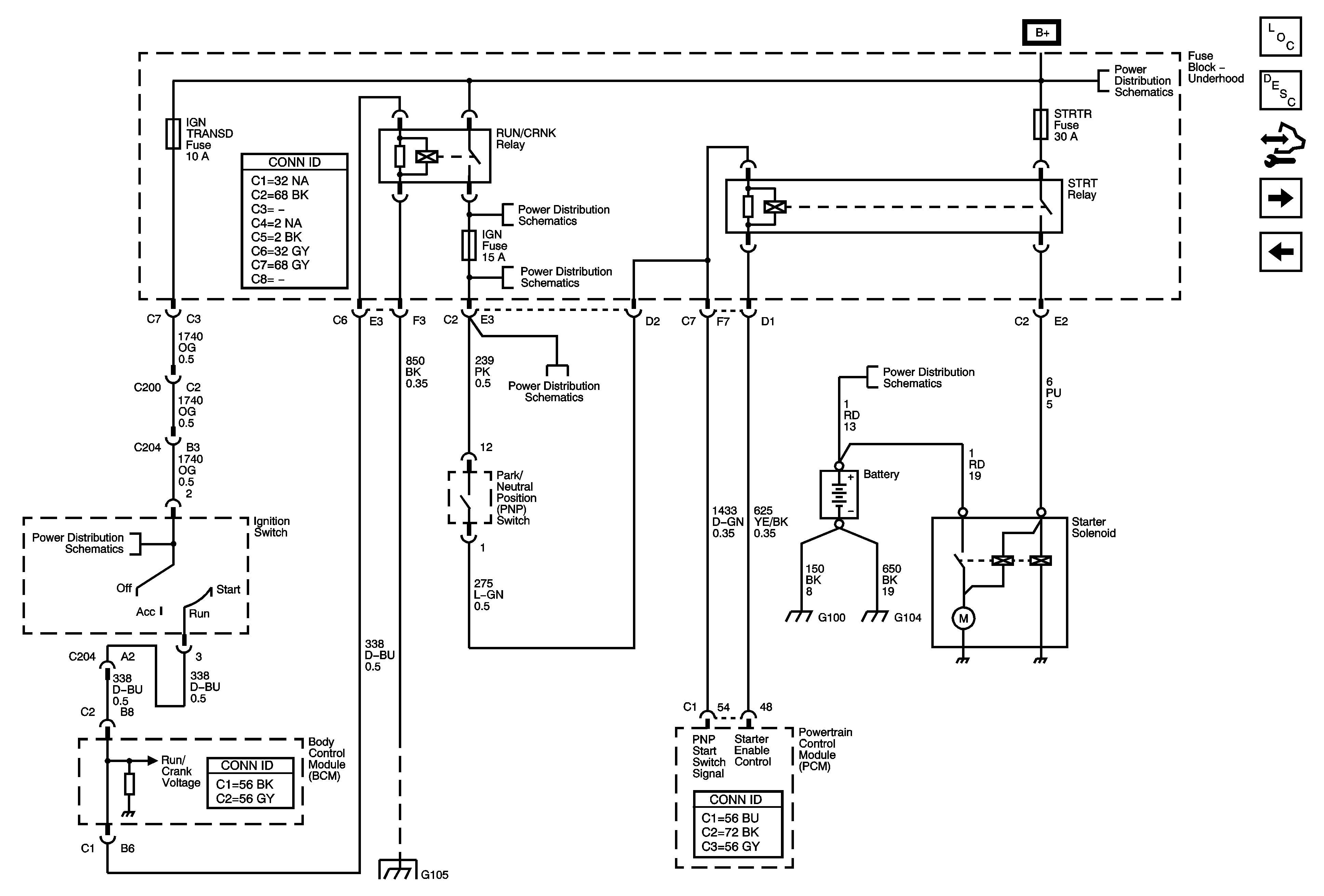
2:
Starting System - M30
Master Electrical Component List
Starting System Description and Operation
Body Control Module Programming and Setup
Charging System
Starting System - MA5
B+ Bus - Underhood Fuse Block
RUN/CRANK RELAY BUS - 2 of 3, ABS, BACKUP, and IGN Fuses
B+ Bus - Underhood Fuse Block
Ignition Switch and IGN TRANS D Fuse
Splice Pack SP1`05 and G105 - 1 of 2
Figure
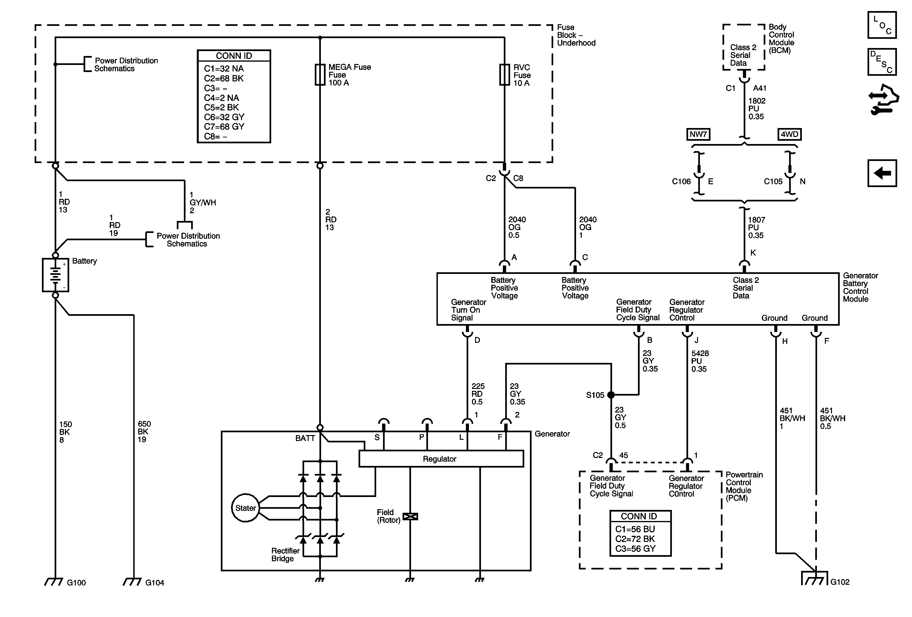
3:
Charging System
Master Electrical Component List
Charging System Description and Operation
Body Control Module Programming and Setup
Starting System - M30
B+ Bus - Underhood Fuse Block