For 1990-2009 cars only
Removal Procedure
- Raise and support the vehicle. Refer to Lifting and Jacking the Vehicle.
- Remove the tire and wheel assembly. Refer to Tire and Wheel Removal and Installation.
- Support the lower control arm with a suitable jack.
- Remove the brake caliper assembly and relocate to the side. Refer to Brake Caliper Bracket Replacement.
- Separate the front wheel drive shaft from the steering knuckle. Refer to Wheel Drive Shaft Replacement.
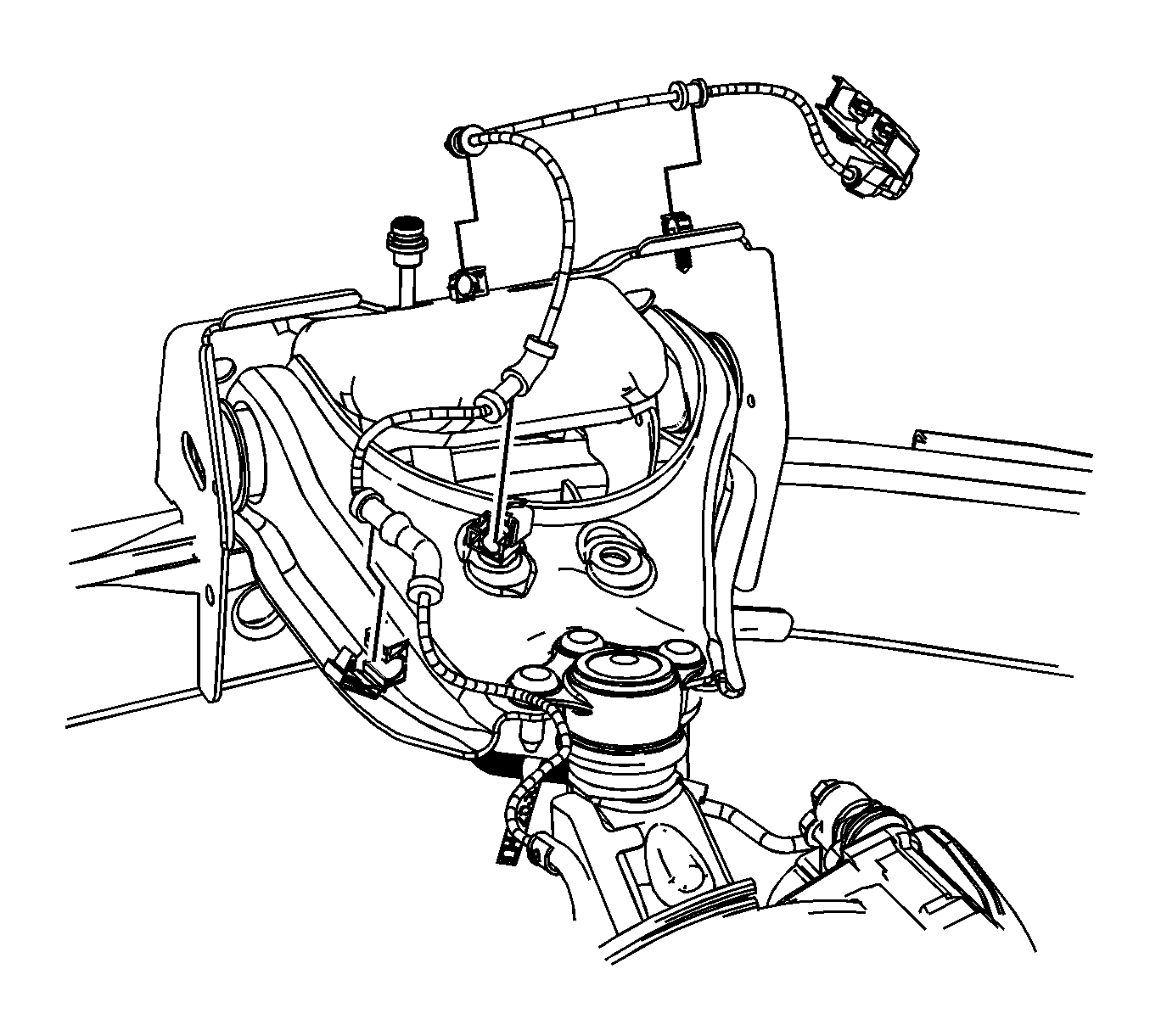
- Remove the speed senor wiring harness from the retaining clips on the upper control arm and frame.
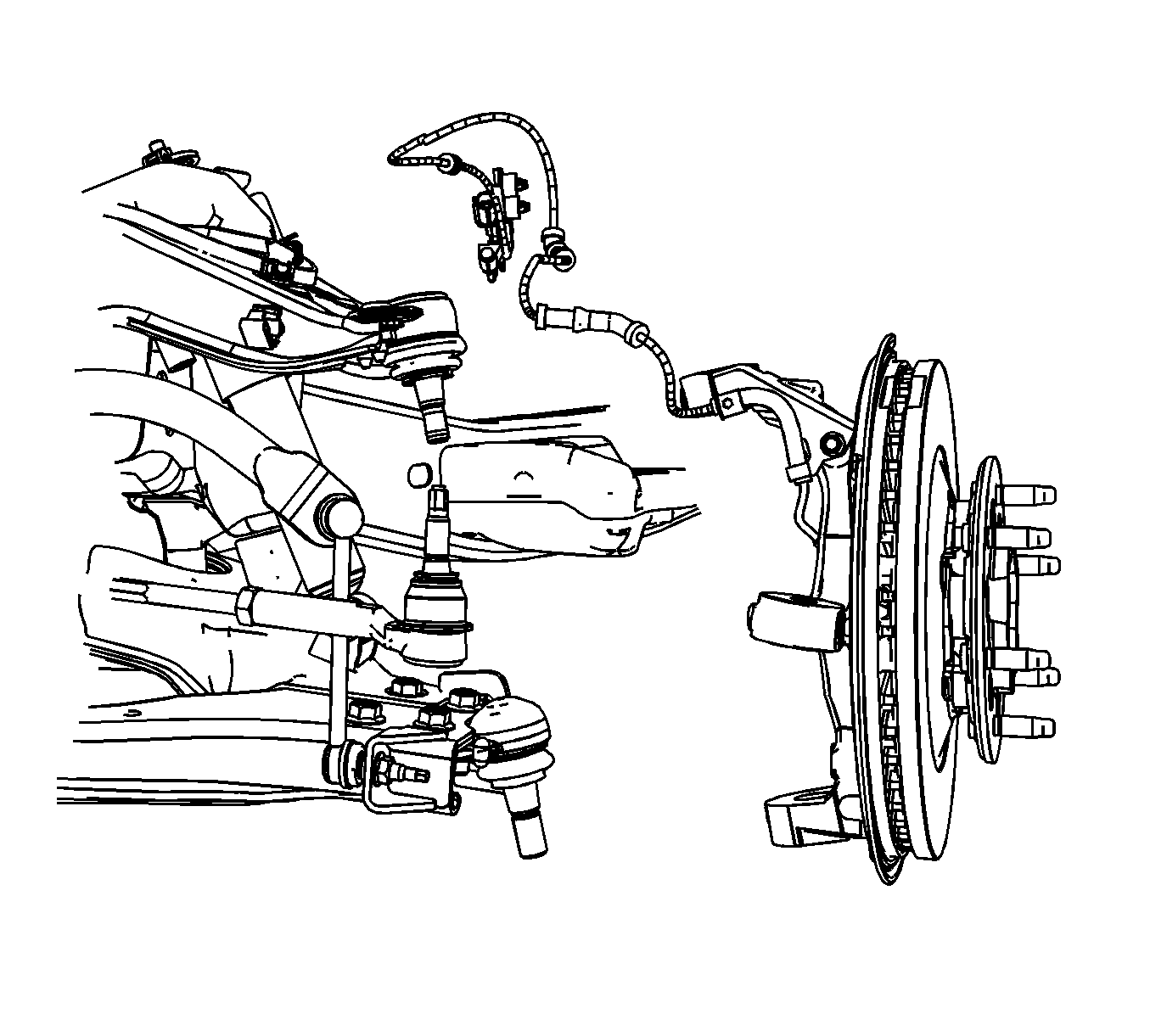
- Remove the outer tie rod end from the knuckle. Refer to Rack and Pinion Outer Tie Rod End Replacement.
- Separate the upper ball joint from the knuckle. Refer to Upper Control Arm Ball Joint Replacement.
- Separate the lower ball joint from the knuckle. Refer to Lower Control Arm Ball Joint Replacement.
- Remove the knuckle from the upper and lower control arms.
- Remove the wheel hub and bearing assembly from the knuckle. Refer to Wheel Hub/Speed Sensor Replacement.
Important: In the following service procedure, it is NOT necessary to separate the brake caliper and mounting bracket. Remove them as an assembly. Support the assembly with mechanics wire or equivalent.
Important: Perform the following service procedure if the vehicle is equipped with 4WD. If the vehicle does not have 4WD, proceed to Step 6.


Important: Remove the wheel hub and bearing assembly and knuckle as a unit.
Installation Procedure
- Install the wheel hub and bearing assembly onto the knuckle. Refer to Wheel Hub/Speed Sensor Replacement.
- Install the lower control arm/ball joint into the knuckle. Refer to Lower Control Arm Ball Joint Replacement.
- Install the wheel drive shaft into the knuckle.
- Install the upper control arm/ball joint into the knuckle. Refer to Upper Control Arm Ball Joint Replacement.
- Install the outer tie rod end into the knuckle. Refer to Rack and Pinion Outer Tie Rod End Replacement.
- Install the speed senor wiring harness in the retaining clips on the upper control arm and frame.
- Install the brake caliper mounting bracket. Refer to Brake Caliper Bracket Replacement.
- Install the wheel drive shaft retaining nut to specifications. Refer to Wheel Drive Shaft Replacement.
- Remove the support from the lower control arm.
- Install the tire and wheel. Refer to Tire and Wheel Removal and Installation
- Remove the support and lower the vehicle.

Important: The following service procedure is for vehicles equipped with 4WD only. If the vehicle is not equipped with 4WD, proceed to Step 4.

