Screen Method for Headlamp Aiming
The screen method requires an area set up specifically for headlamp aiming.

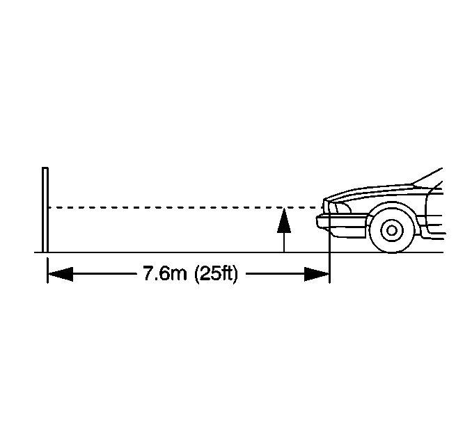
The area should consist of a level surface large enough to allow for a vehicle and an additional 7.62 m (25 ft) as measured from the face of the headlamps to the aiming screen.

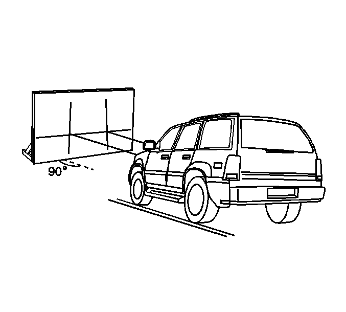
The screen should be a wall or other flat surface at least 1.52 m (5 ft) high by 3.66 m (12 ft) wide with a matte white surface well shaded from extraneous light, and 90 degrees to the floor. The screen should be provided with a permanent vertical reference line 0.61 m (2 ft) from the left edge of the screen, 2 laterally adjustable vertical tapes, and one vertically adjustable horizontal tape.
After the aiming screen has been set up and located, paint or tape a reference line on the floor 15.24 m (50 ft) from the vertical reference line on the screen. This line should be perpendicular to the aiming screen and a mark placed at 7.62 m (25 ft) from the screen.
Headlamp Aiming Procedure
- Align the left tires of the vehicle with the reference line extending from the screen with the headlamps aligned with the reference line.
- Remove any snow, ice or mud from the vehicle.
- The vehicle must be fully assembled and all other work stopped while the headlamp aiming is being done.
- The vehicle must contain one person or approximately 160 lb (73 kg).
- Tires should be properly inflated.
- Rock the vehicle to stabilize the suspension.
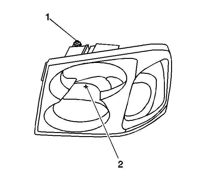
- Measure from the floor to the reference mark on the headlamp lens (2).
- At the screen, measure from the floor and place the horizontal tape at the above measured distance.
- Turn the low beam headlamps ON.
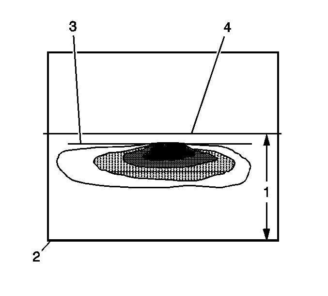
- The graphic shows the vertical (1) adjustment, no horizontal adjustments are required.
- The beam pattern must be positioned as shown in the graphic.
- Adjust one headlamp at a time while blocking the light from the other. The cover must be away from the headlamp.

Adjust the headlamps to the specifications required by state and local authorities.

Important: Do not place a cover directly on the headlamp assembly while the headlamp is ON.
The following list refers to the callouts in the graphic:
| • | The low beam centerline reference mark (4). |
| • | Distance from ground to the low beam bulb centerline reference mark (1). |
| • | The ground line (2). |
| • | Horizontal edge of the low beam headlamp pattern (3). |
| • | The edge of the headlamp pattern (3), must be 5 cm (2 in) below the reference mark (4), with the vehicle 7.62 m (25 ft) away. |
