For 1990-2009 cars only
Removal Procedure
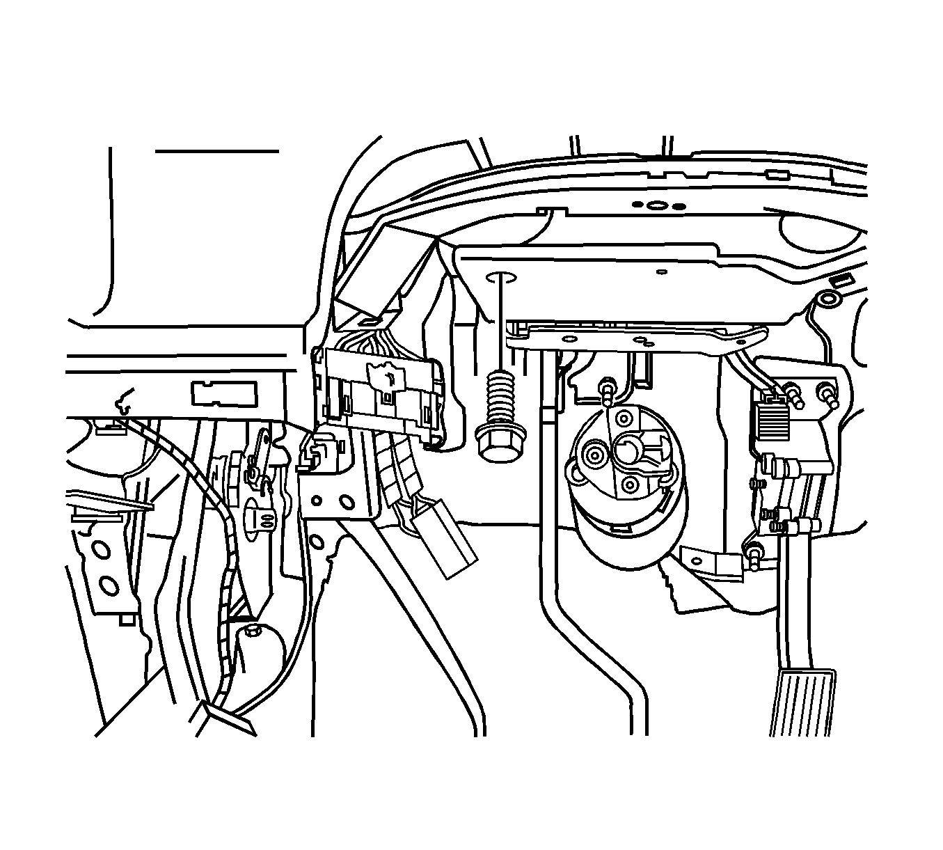
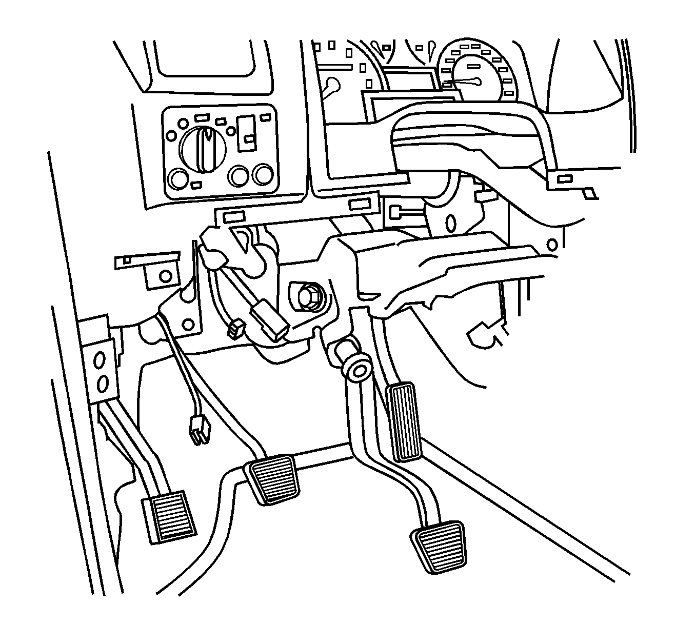
Important: The brake pedal and support bracket are one piece. The brake pedal is not serviced separately from the support bracket.
- Remove the steering column assembly. Refer to Steering Column Replacement .
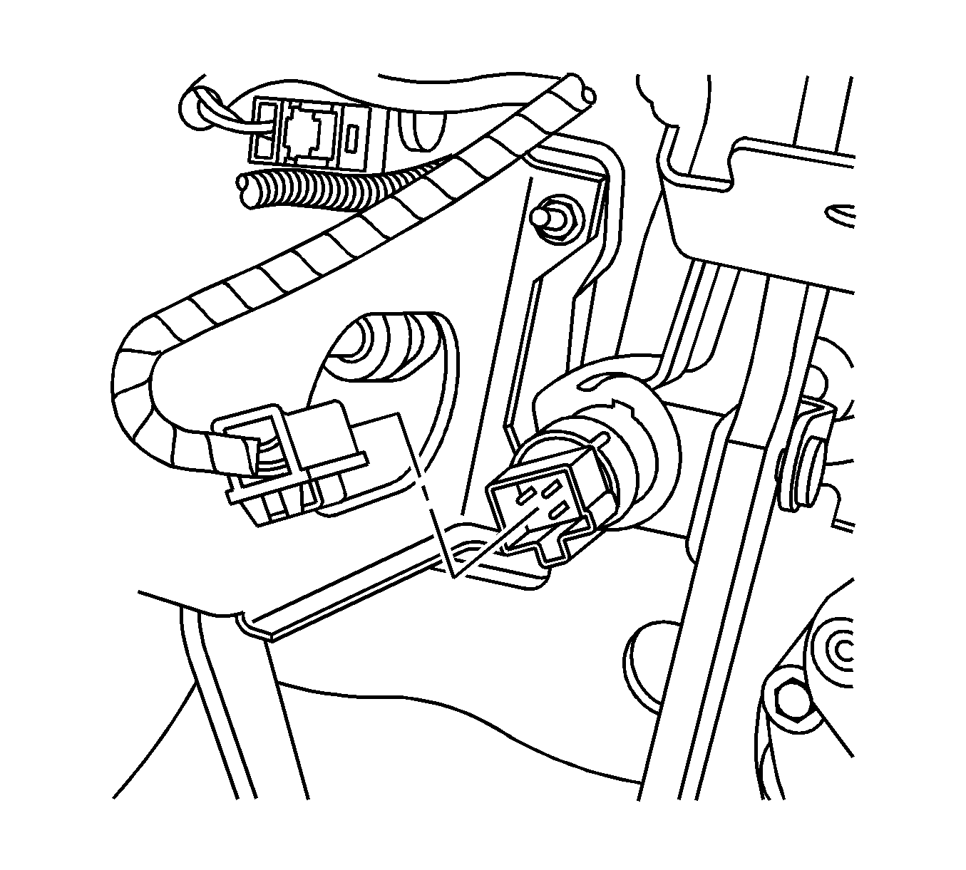
- Remove the stop light switch electrical connector.
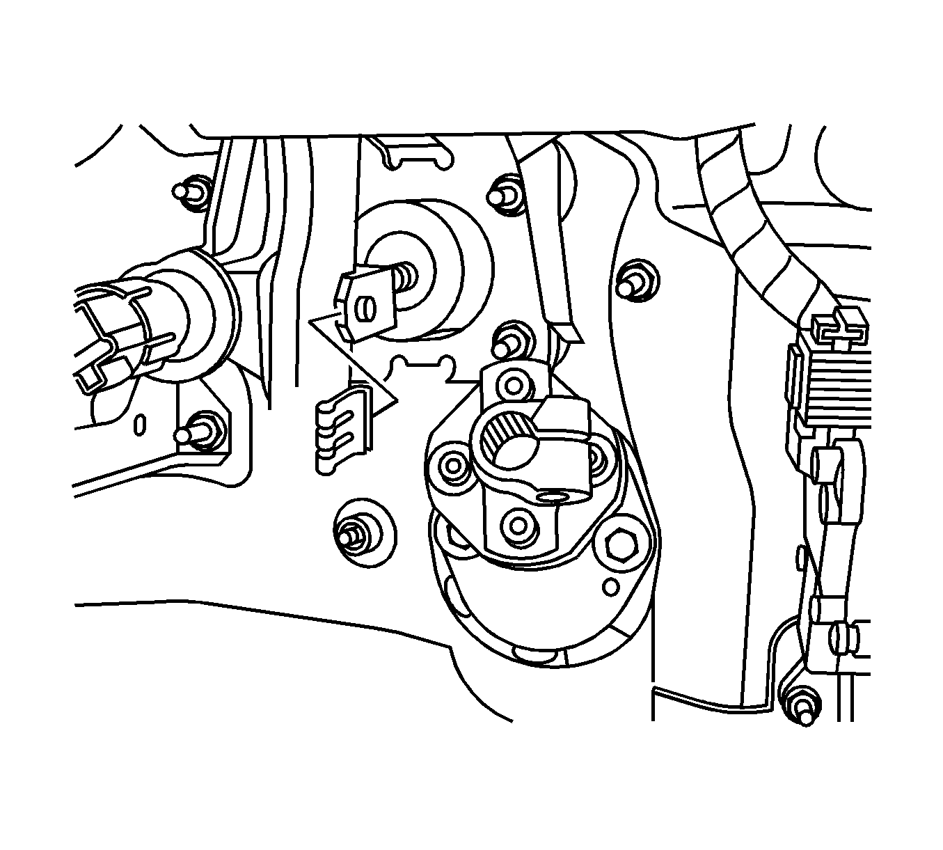
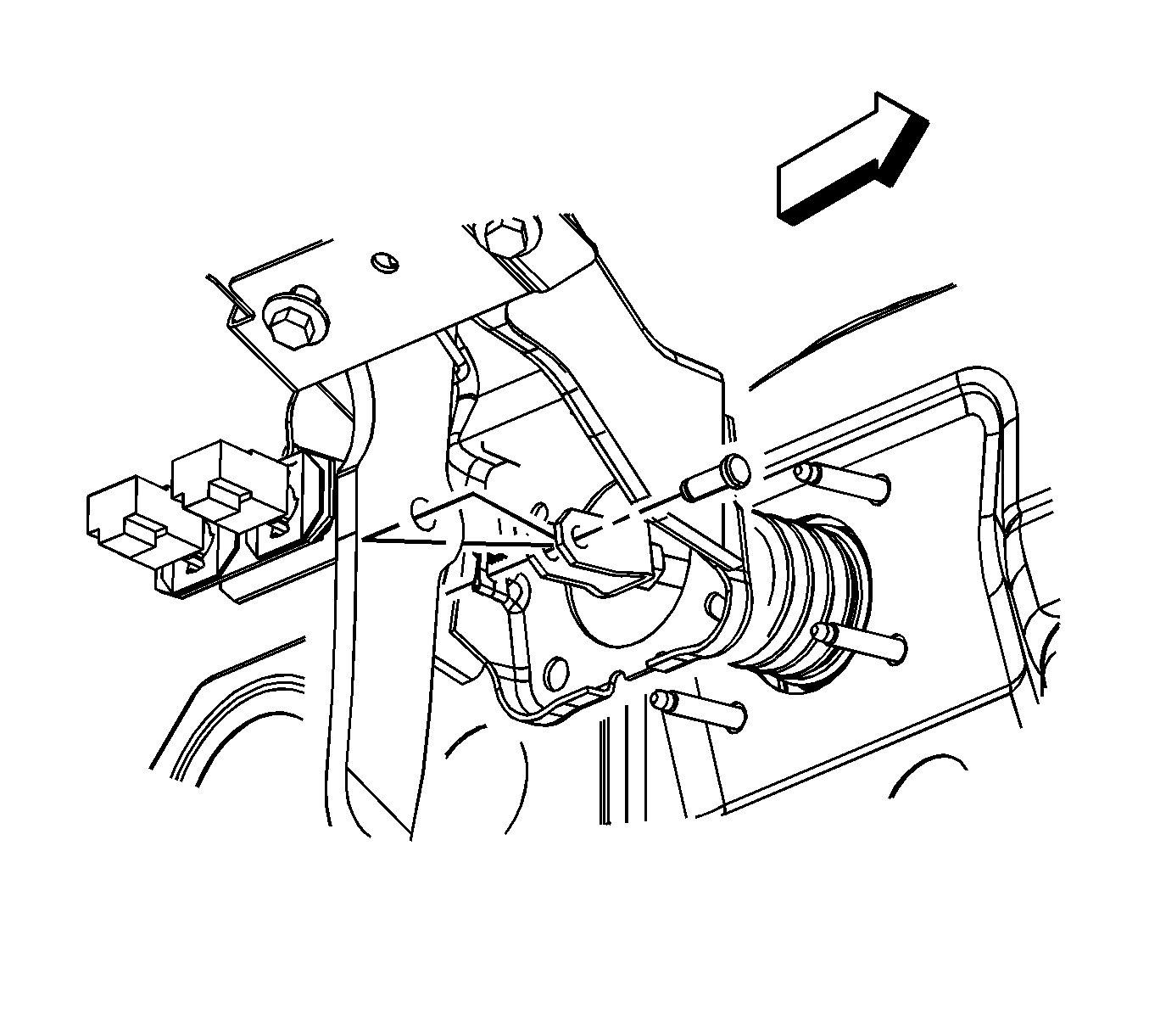
- Remove the retaining clip for the clevis pin.
- Remove the clevis pin.
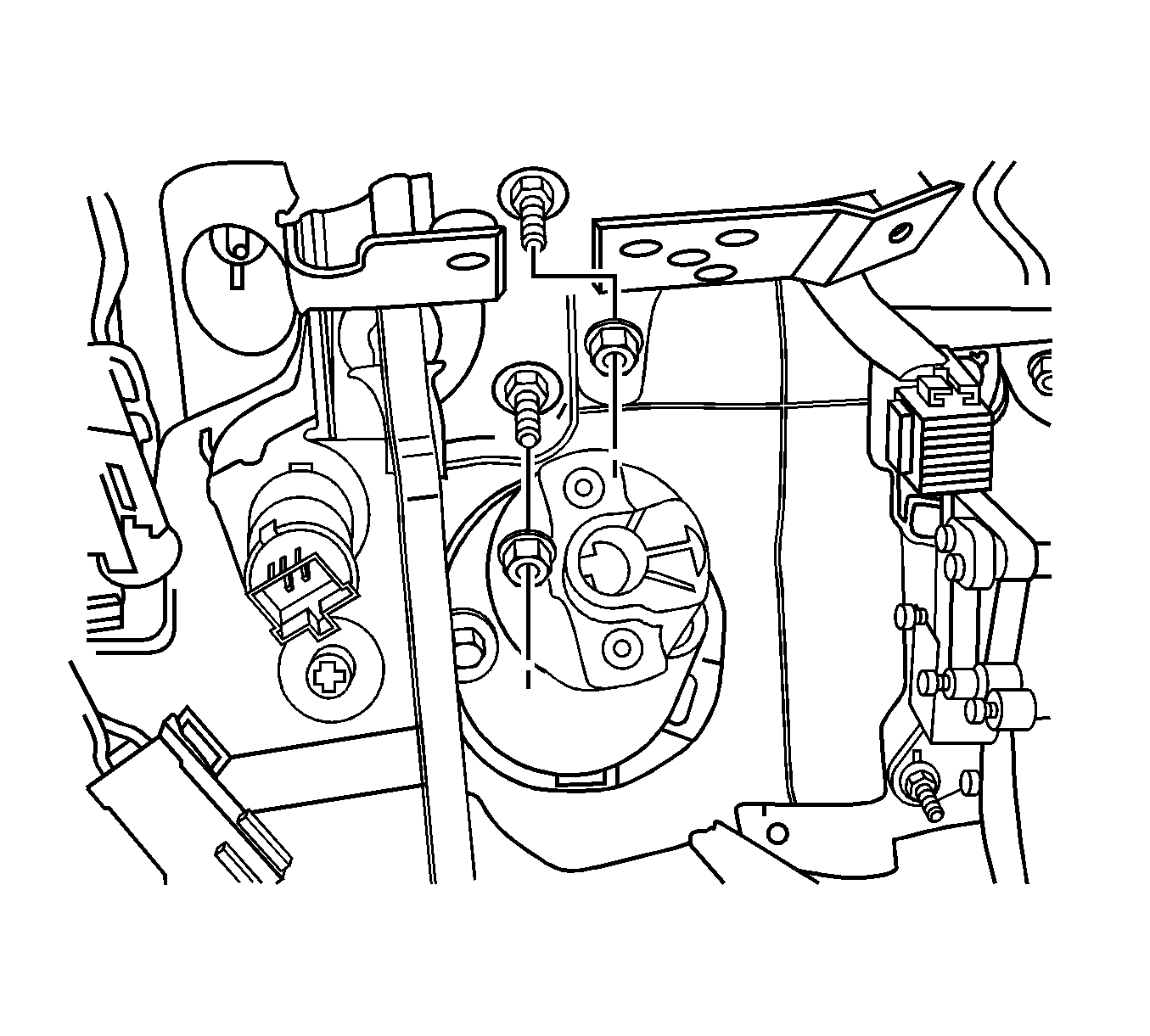
- Remove the vacuum brake booster mounting nuts.
- Remove the brake pedal support bracket mounting bolts.
- Remove the brake pedal assembly.
- Remove the stop lamp switch.
Installation Procedure
- Install the stop lamp switch.
- Install the brake pedal support bracket.
- Install the brake pedal support bracket mounting bolts.
- Install the vacuum brake booster mounting nuts.
- Install the retaining clip for the clevis pin.
- Adjust the stop lamp switch. Refer to Stop Lamp Switch Adjustment .
- Adjust the cruise control release switch. Refer to Cruise Release Switch Adjustment .
- Install the stop lamp electrical connector.
- Install the steering column assembly. Refer to Steering Column Replacement .

Notice: Refer to Fastener Notice in the Preface section.

Tighten
Tighten the brake pedal mounting bolts to 27 N·m (20 lb ft).

Tighten
Tighten the vacuum brake booster mounting nuts to 20 N·m (15 lb ft).


