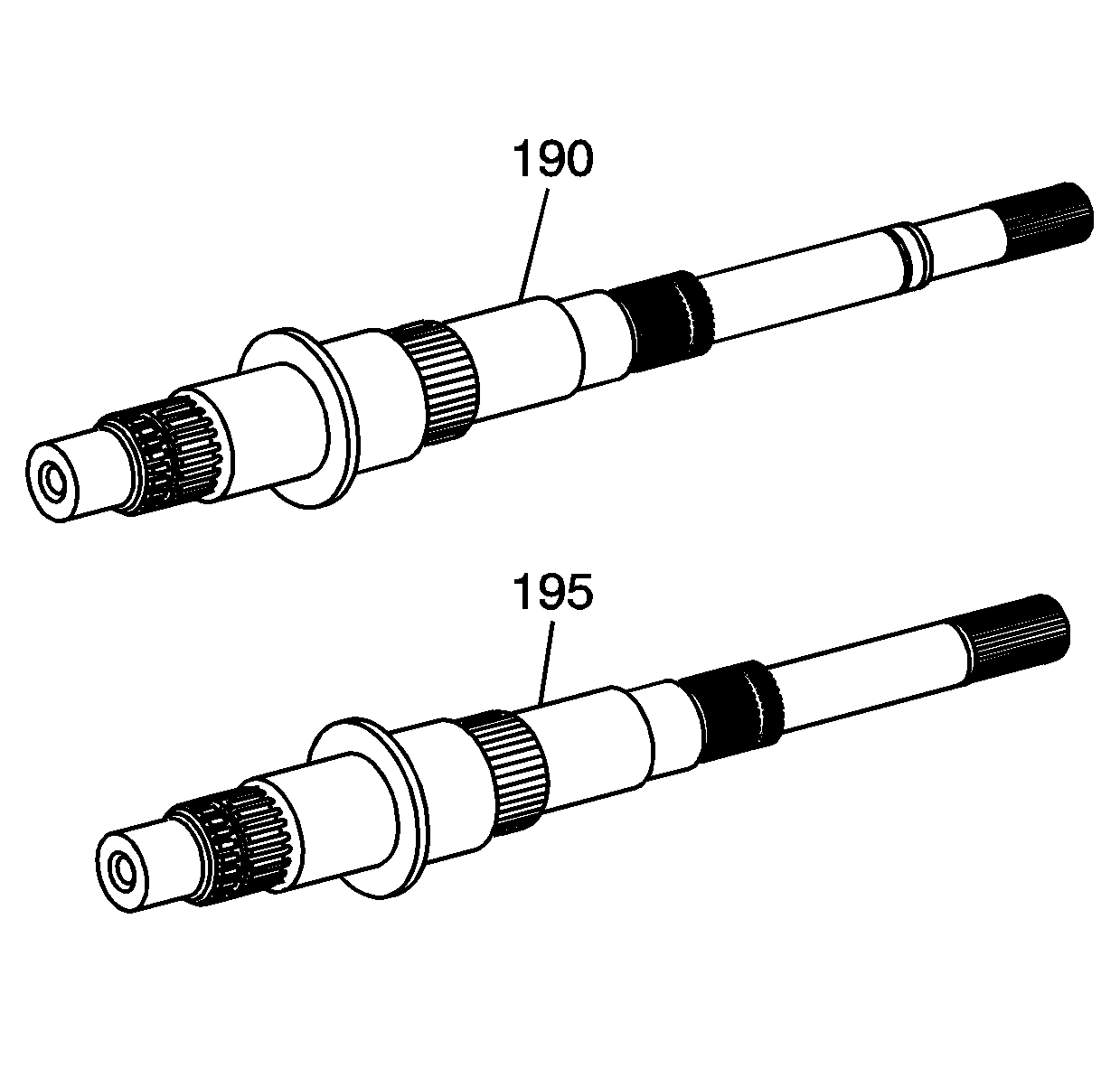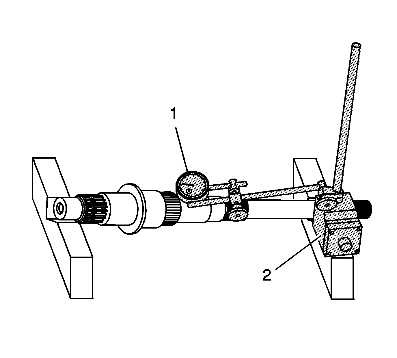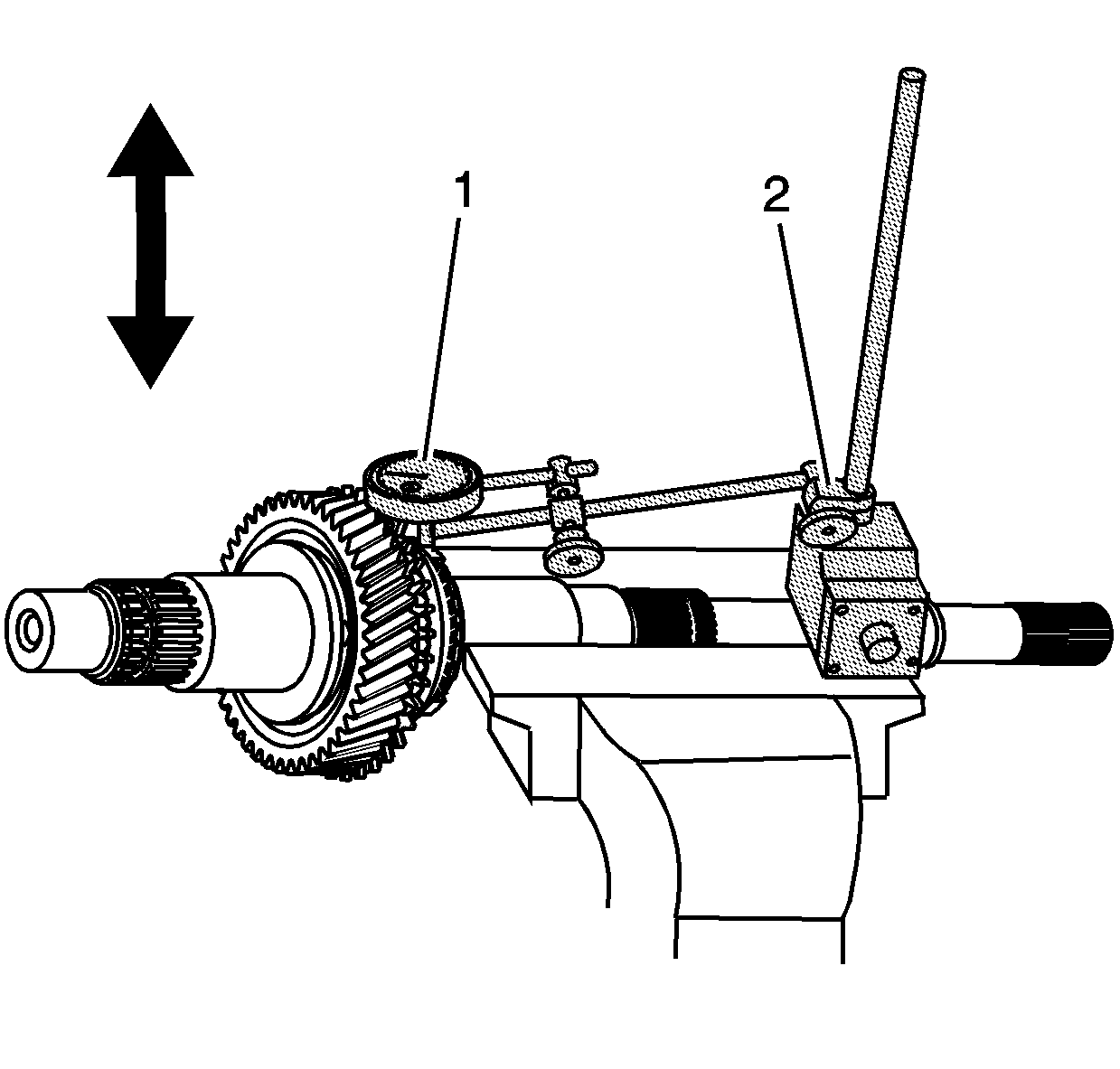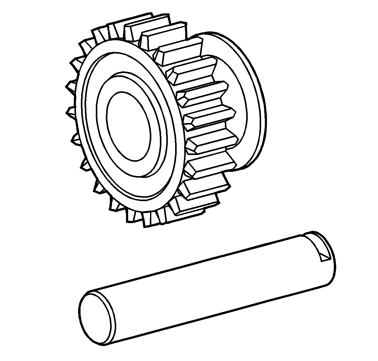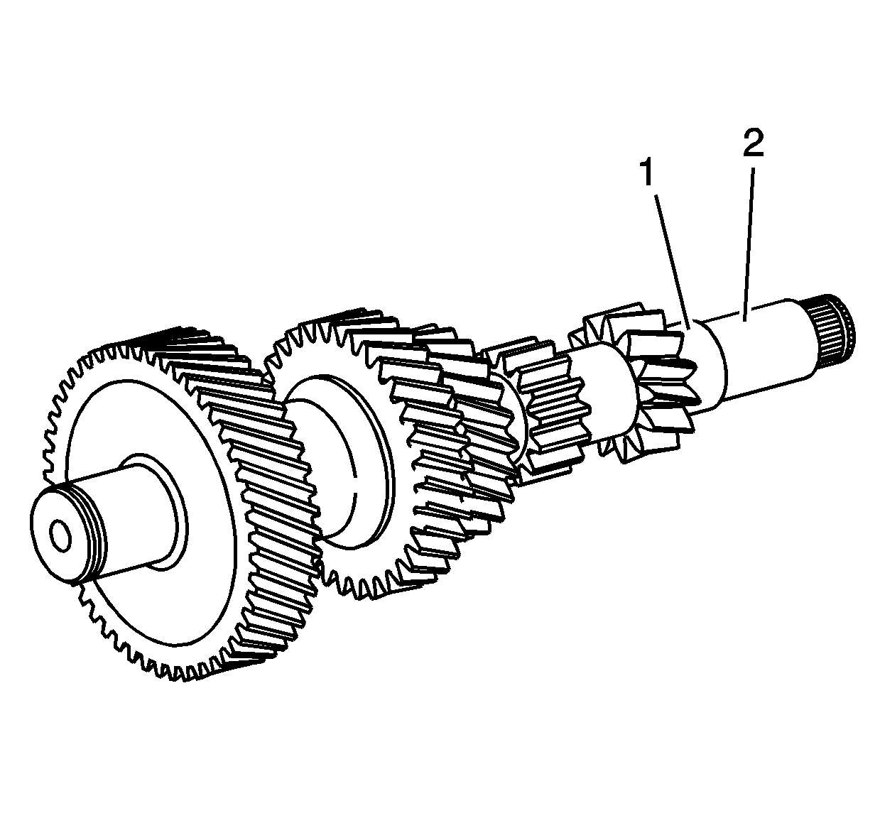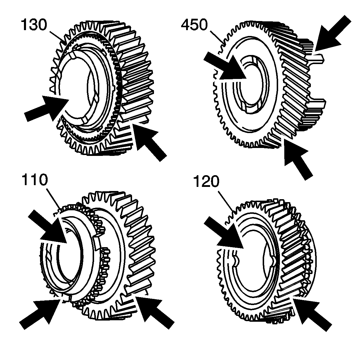
- Clean the 1st gear (110),
the 2nd gear (120), the 3rd gear (130), and the 5th countershaft
gear (450) in a suitable solvent and air dry all the parts.
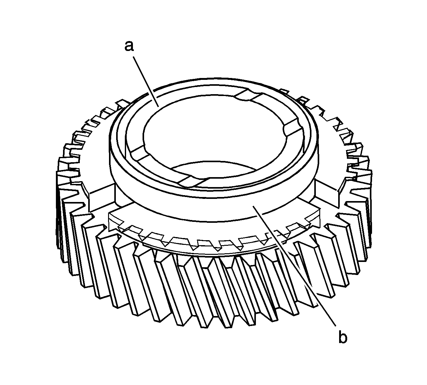
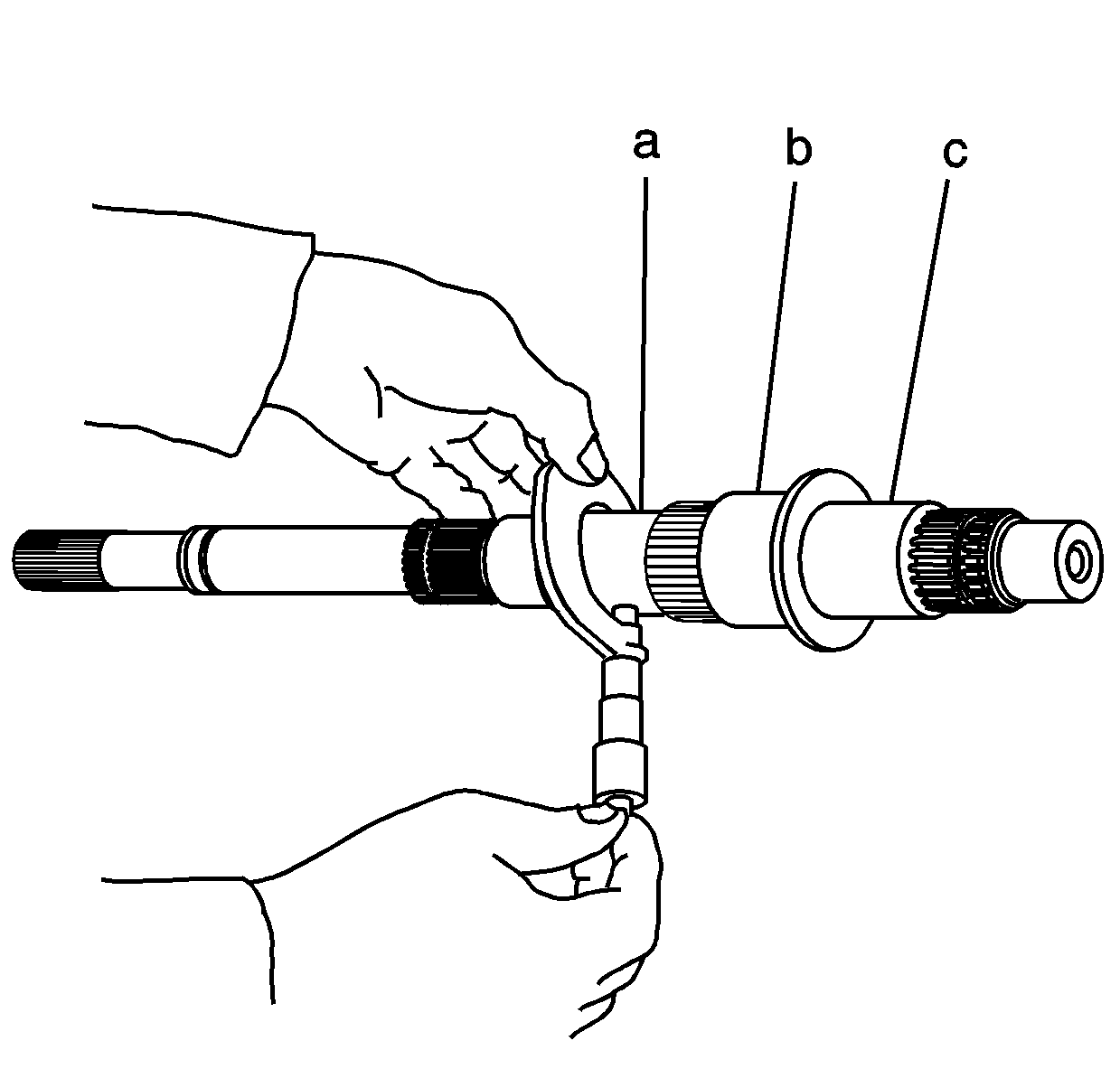
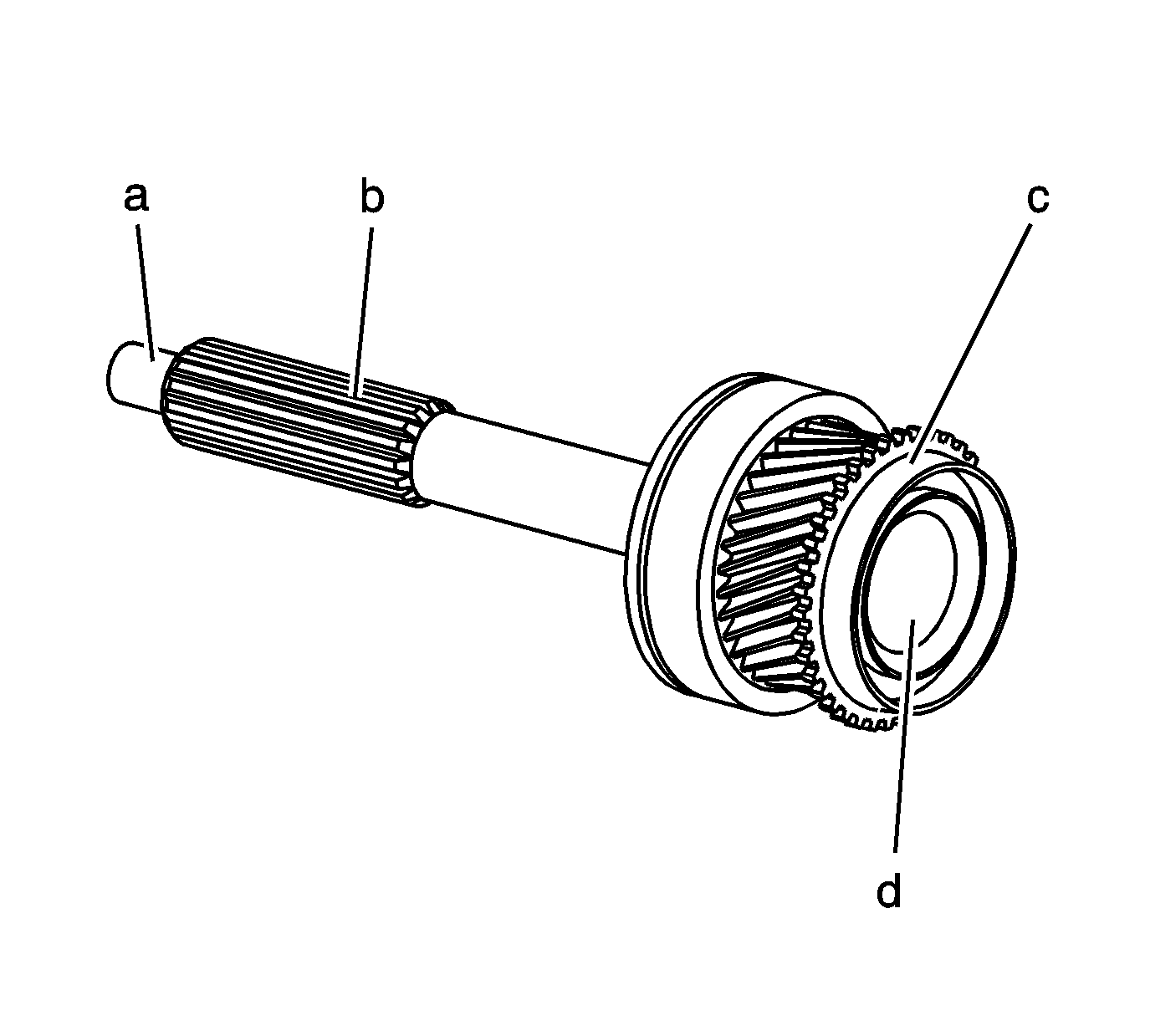
- Inspect the thrust surfaces (a)
on both sides of the gears for the following conditions:
- Replace any gears that have faulty thrust surfaces. Worn thrust
surfaces may cause gear clashing or hard shifting, by not allowing full
engagement of the synchronizer blocking rings. Worn thrust surfaces may also
cause gear noise or may cause clunking during acceleration or deceleration.
- Inspect the synchronizer blocking ring surface (b) for
the following conditions:
- Replace any gear that has a faulty blocking ring surface.
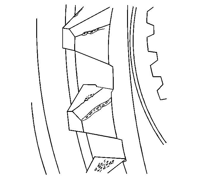
- Inspect the selector teeth
of the gears for gear change damage.
If there is gear change
damage, the tooth edges are worn and chipped and, in some cases, affected
by plastic deformation because of high shift loads that resemble ragged
edges. Such severe deformation of the selector teeth edges causes hard gearshift
changes. The spline flanks may also show signs of wear resembling fretting
corrosion.
- If gear change damage is present, replace or repair the affected
parts. Gear change damage is caused by any of the following conditions:
| • | Corresponding speeds of gears not adequately matched |
| • | Operating the transmission incorrectly |
| • | Incorrect clutch operation |
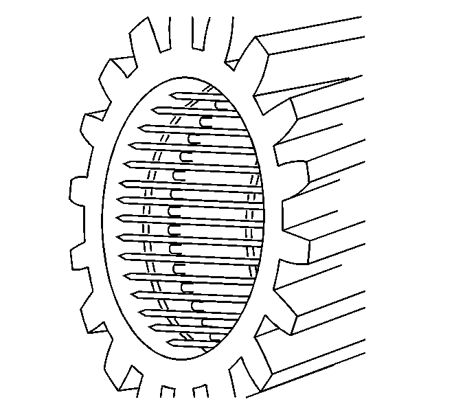
- Inspect the gears for
brinelling.
Brinelling occurs on the roller races of the gears
and is characterized by what appears to be the impression of the bearing rollers.
- Replace any gears showing brinelling.
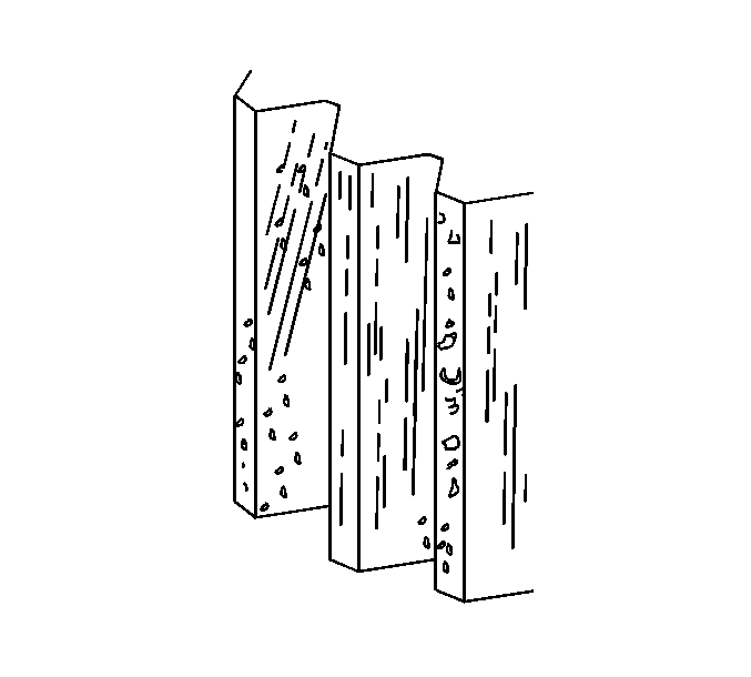
- Inspect the gears for
break-in-wear or running-in-wear.
Break-in-wear is not considered damage because it usually ceases
after the running-in-period has expired, without damaging the
components. Rough peaks produced during manufacture are worn away or, to some
extent, are rolled into the surface. The grinding and shaving marks on the
surface are still visible.
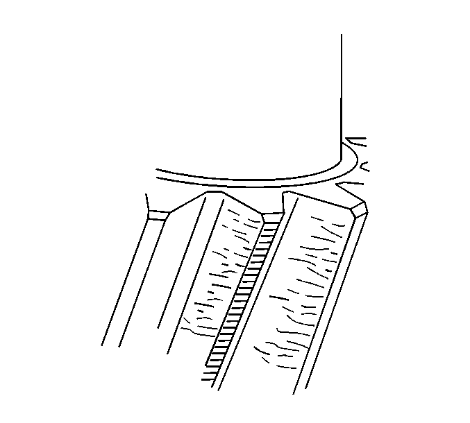
- Inspect the gear teeth
for scratches.
Scratches are linear indentations on the flank,
running in the direction of sliding.
- If scratches are present, replace the affected parts.
Scratches can be caused by the following conditions:
| • | Dust and abrasive particles, including those caused by flank contact,
in the lubricating oil |
| • | The sliding action of the flanks |
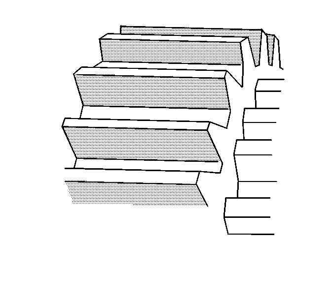
- Inspect the gear teeth
for abrasive wear.
The marks left by the machining process
are erased from the active flank. Instead, the entire flank takes on a matte
gray appearance. Substantial changes take place in the tooth profile and
clearance once abrasive wear has reached an advanced stage. This not only
increases the noise level, but can also cause secondary damage.
- If abrasive wear is present, replace the affected parts.
Abrasive wear is caused by the following conditions:
| • | Oil contamination resulting from wear or surface fatigue in other
areas of the transmission |
| • | Sand, sludge, etc. penetrating into the transmission from the
outside |
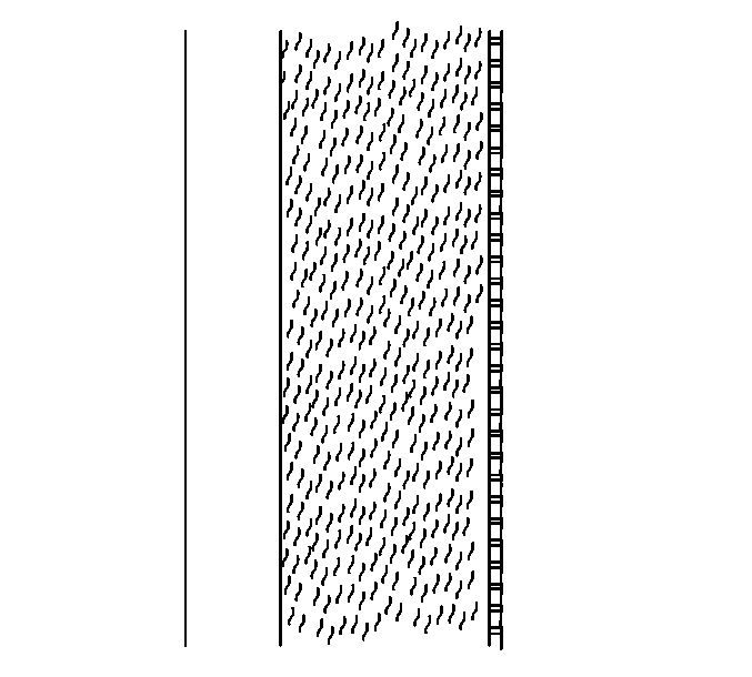
- Inspect the gear teeth
for rippling or brinelling.
The polished tooth flanks show
signs of ripple-like alterations in the surface structure, which run
perpendicular to the direction of sliding, and may resemble a washboard.
- If rippling or brinelling is present, replace the affected parts.
Rippling or brinelling is caused by the following conditions:
| • | A combination of inadequate lubrication, high flank loads and
low peripheral speeds |
| • | Friction-induced vibration |
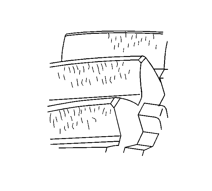
- Inspect the gear teeth
for light scoring.
Light scoring is identified as rough, partially
porous lines or areas aligned in the direction of sliding. When the film of
lubricant is torn away between the flanks, this permits direct metal-to-metal
contact causing seizure or welding. These welded zones are immediately torn
apart again, producing the damage associated with scoring. Scoring initially
occurs in areas subjected to high hertz frequency stresses and high sliding
speeds, usually along the tooth root and tooth tip. Light scoring only covers
a part of the entire surface of the flank, or is not strongly developed and
has caused only insignificant wear after smoothing.
- If light scoring is present, replace the affected parts.
Light scoring is caused by the following conditions:
| • | Inadequate oil viscosity |
| • | Unfavorable gear geometry |
| • | Temporary lack of lubricant |
| • | Faulty heat treatment of the gears |
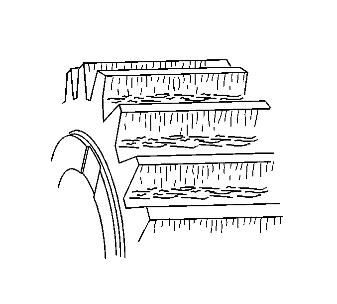
- Inspect the gear teeth
for severe scoring.
Severe scoring is the same as light scoring,
except large areas of the tooth flank are affected. At an advanced stage,
the flank may heat up to such an extent that localized discoloring occurs.
- If severe scoring is present, replace the affected parts.
Severe scoring is caused by the following conditions:
| • | Inadequate oil viscosity |
| • | Unfavorable gear geometry |
| • | Temporary lack of lubricant |
| • | Faulty heat treatment of the gears |
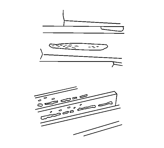
- Inspect the gears for
flank fatigue, causing gray spots.
Gray spots are localized
pittings on the flank caused by material fatigue and extremely fine pittings
formed on the load-bearing flanks. If they are in cluster, they appear
to the naked eye as matte gray staining. Under high magnification, a large
number of microscopic cracks become visible on the flank. Pittings originating
from these cracks may create the appearance of local flank wear. Most of
the gray spots are located in the root zone of the gear teeth.
- If gray spots are present, replace the affected parts.
Gray spots are caused by the following conditions:
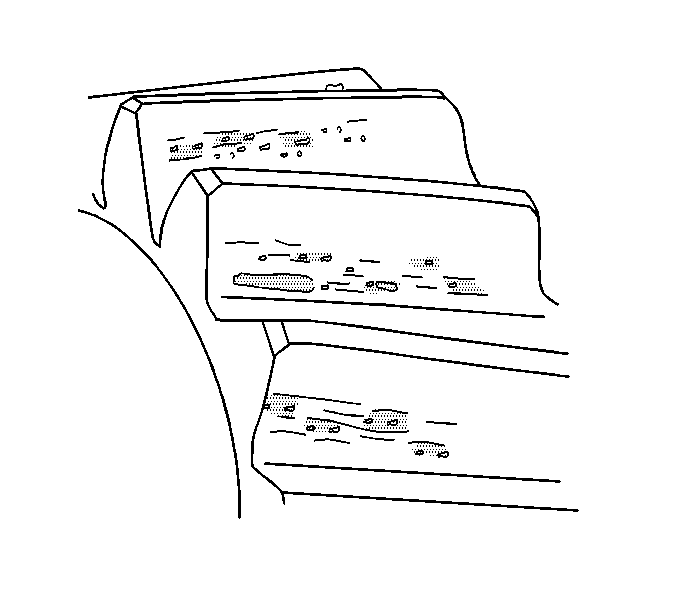
- Inspect the gear teeth
for slight pittings.
Slight pittings are identified as pore-like
areas of individual pittings on the flank caused by material fatigue. Usually,
slight pittings are only present in the root zone of the flank. Slight pittings
may cease after run-in. A change in operating conditions may also
stop continued development of slight pitting.
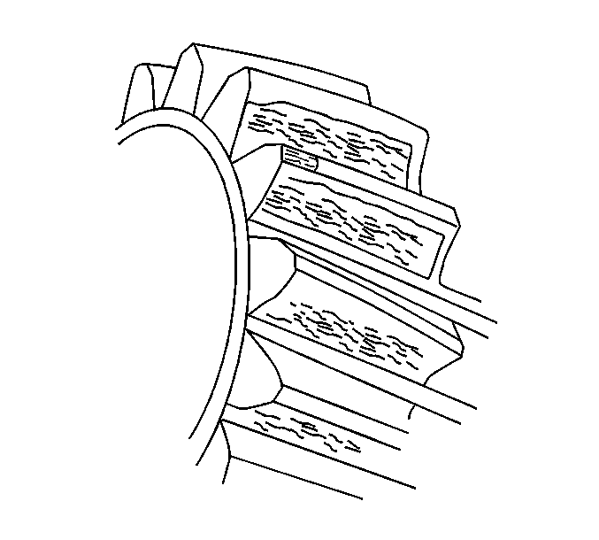
- Inspect the gear teeth
for pittings.
Pittings are material fatigue on the flank. The
total pitting surface may become so large that smooth running is considerably
impaired, or the remaining flank face still bearing the load will soon be
destroyed by wear.
- If pittings are present, replace the affected parts.
Pitting is caused by the following conditions:
| • | Exceeding the sliding and rolling stresses for the material |
| • | Incorrect oil viscosity |
| • | Excessive operating temperature |
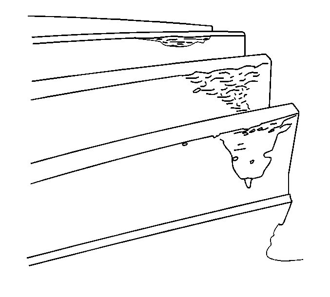
- Inspect the gears for
spalling.
Spalling is extensive triangular pits on the flank,
spreading from a zone of gray spots or a fine line of pits at the root.
The depth of the exposed surface is relatively constant throughout. Further
cracks may extend from the pits at an angle. In some cases, the damage may
even progress into the tip zone, causing tip damage.
- If spalling is present, replace the affected parts.
Spalling is caused by the following conditions:
| • | Exceeding the sliding and rolling stresses for the material |
| • | Incorrect oil viscosity |
| • | Excessive operating temperature |
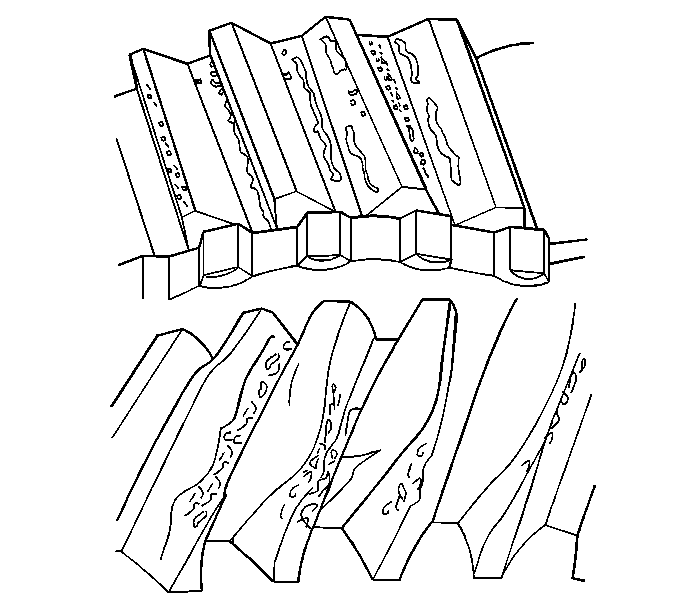
- Inspect the gears for
damage from overheating.
Overheating damage is identified by
grayish to bluish black discoloration of the gear, burnt oil, and reduced
hardness. Due to the reduction in hardness, there is scored or grooved flank
wear in the direction of sliding, particularly in the tip and root zones.
If there is extreme overheating, the material softens, causing distortion
of the gear teeth, bending the teeth from thermal distortion.
- If damage from overheating is present, replace or repair the affected
parts.
Overheating is caused by the following conditions:
| • | Temporary or complete lack of lubrication - low oil level |
| • | Very high peripheral speeds |
| • | Insufficient tooth clearance |
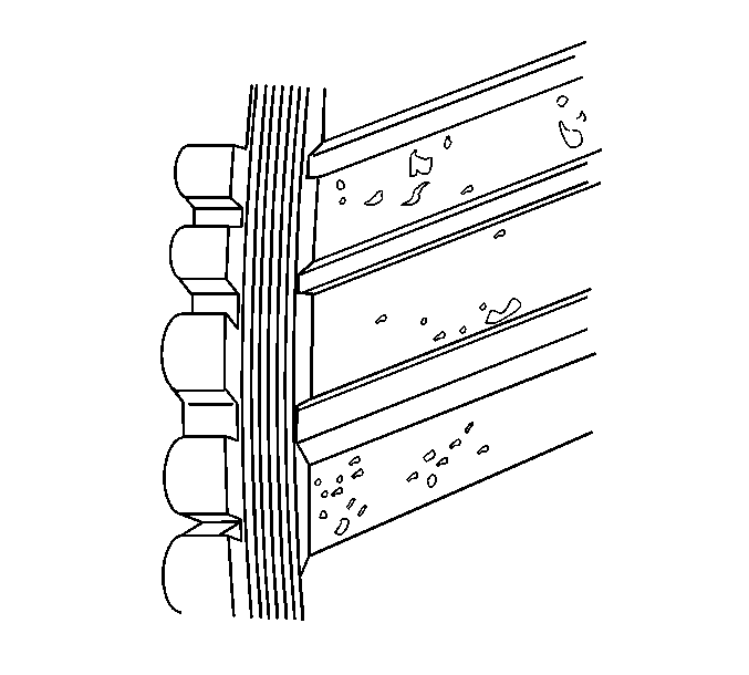
- Inspect the gears for
corrosion.
Corrosion is brownish red to black spots, sometimes
with local material loss on the flank. If corrosion has not caused material
loss to the flank, the sliding and rolling action of the flank can help
to remove some of the corrosion.
- If corrosion is severe, replace the affected parts.
Corrosion is caused by the following conditions:
| • | Water or salt water entering the transmission |
| • | Condensation forming under unfavorable operating conditions |
| • | Oil aging and the decomposition of corrosion inhibitors |
