GM Service Manual Online
For 1990-2009 cars only
Makes
🢒
Isuzu
🢒
2005
🢒
Isuzu H-Series
🢒
Vehicle Control Systems
🢒
Vehicle DTC Information
🢒 Instrument Cluster Schematics
Figure
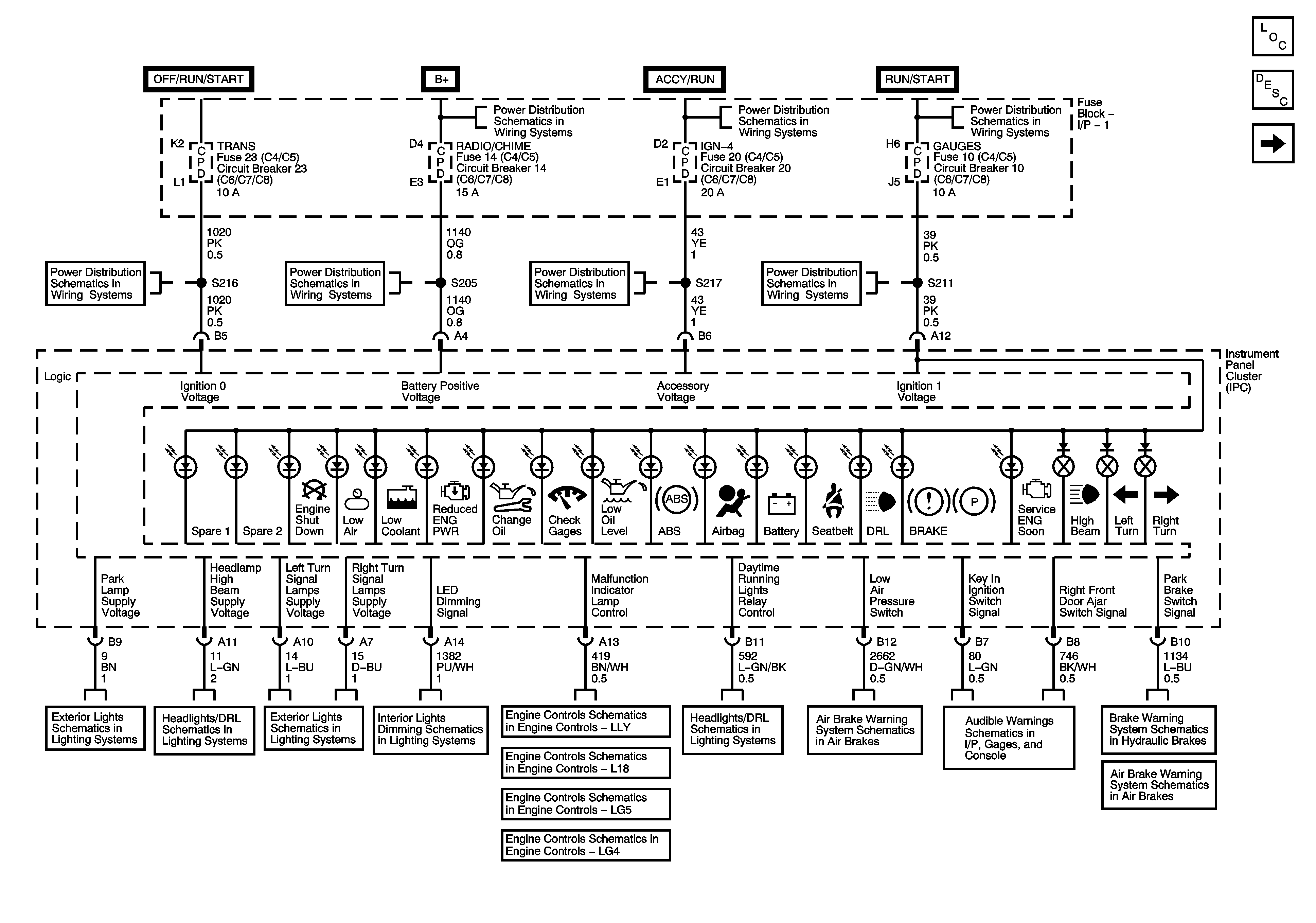
1:
Instrument Panel Cluster - 1 of 2
Master Electrical Component List
Instrument Cluster Description and Operation
Instrument Panel Cluster - 2 of 2
RADIO/CHIME, CHMSL, and PWR POST Fuses/Circuit Breakers
B+ Bus Bar
Ignition Switch, OFF/RUN/START, RUN/START, and START Bus Bars
I/P Fuse Block, START and TRANS Fuses/Circuit Breakers
RADIO/CHIME, CHMSL, and PWR POST Fuses/Circuit Breakers
I/P Fuse Block, IGN 4, and AUX RLY Fuses/Circuit Breakers
I/P Fuse Block, R-RR TRUCK, L-RR TRUCK, GAGES, and SIR Fuses/Circuit Breaker
Instrument Panel Cluster - 2 of 2
Park Lamps, Roof Marker Lamps
Headlights, Daytime Running Lamps (DRL)
Hazard and Turn Signal
Interior Dimming Lamps System
Data Link Connector, Power, and Ground - 2 of 2
Controlled/Monitored Subsystem References
G100 (L18)
Figure
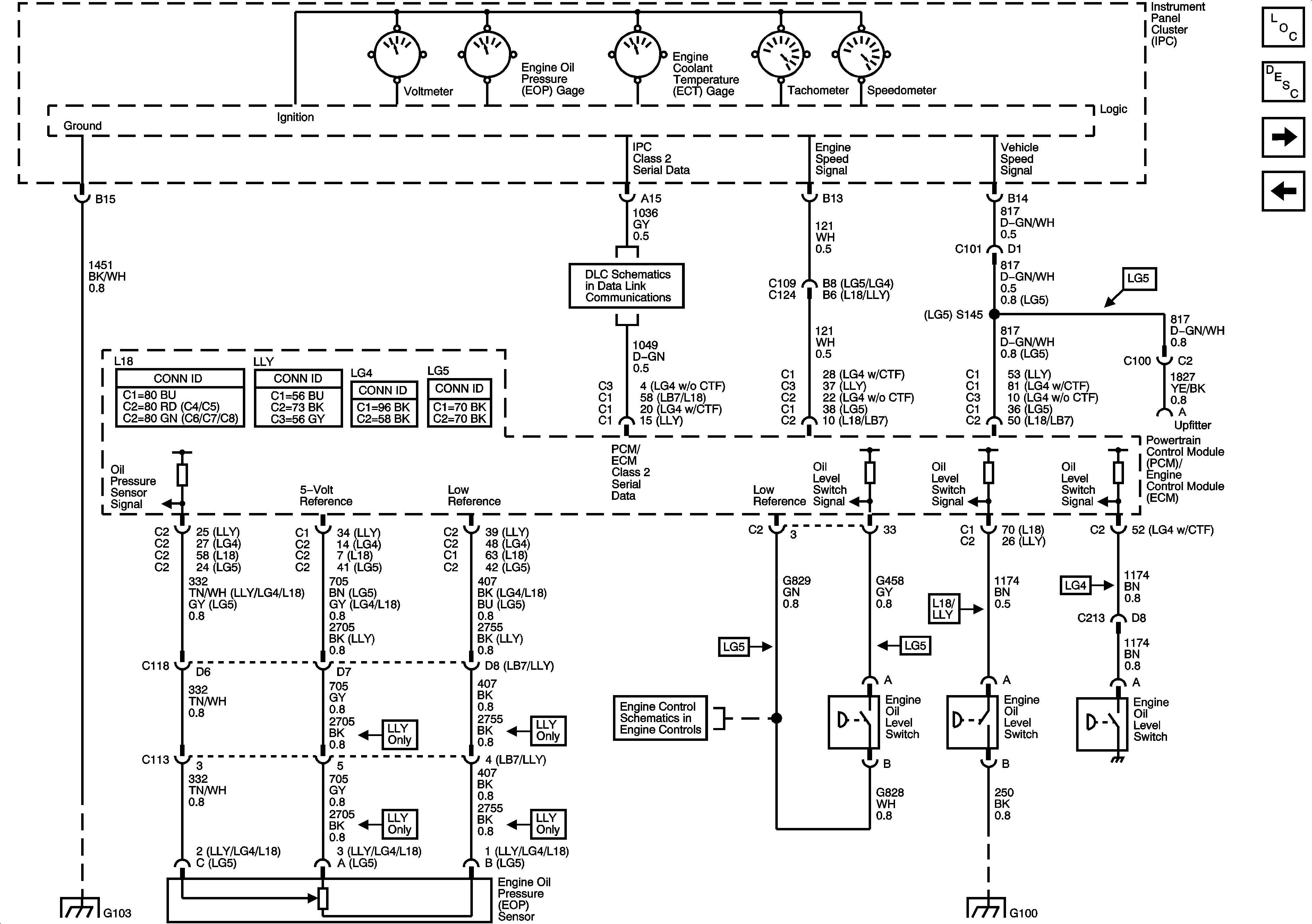
2:
Instrument Panel Cluster - 2 of 2
Master Electrical Component List
Instrument Cluster Description and Operation
Fuel Senders
Instrument Panel Cluster - 1 of 2
Brake Warning System Schematics - Hydraulic
Audible Warning
Module Power, Ground, Serial Data, and MIL
Instrument Panel Cluster - 1 of 2
Air Brakes Schematics
G103 - 2 of 2
Figure
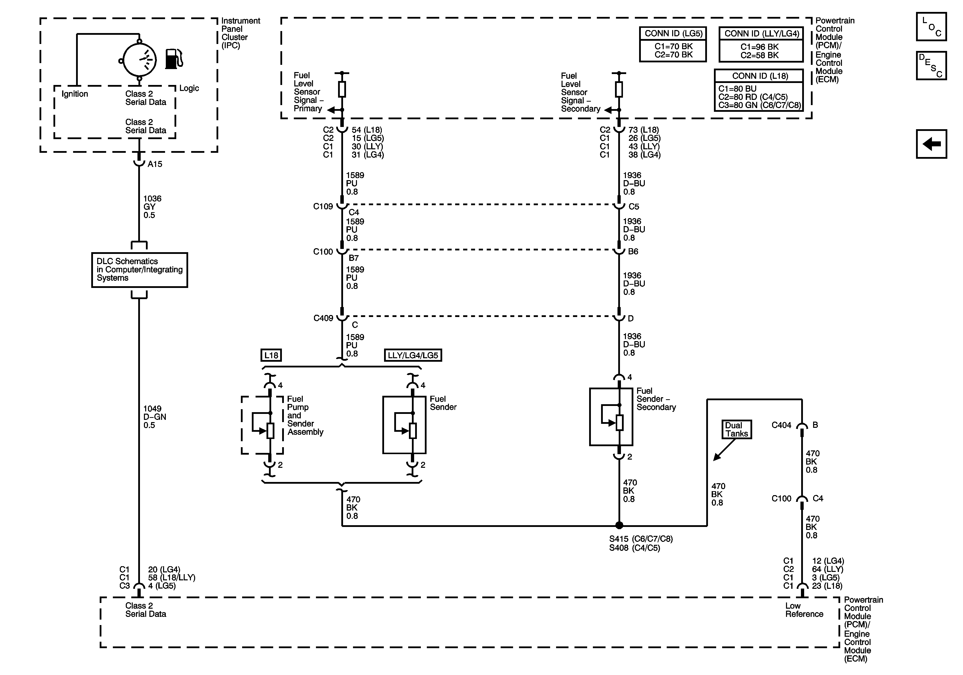
3:
Fuel Gage
Master Electrical Component List
Instrument Cluster Description and Operation
Instrument Panel Cluster - 2 of 2
Splice Pack SP203 (L18/LB7/LG4)
Engine Data Sensors - Pressure and Temperature