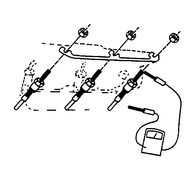
For 1990-2009 cars only
Glow Plug Replacement Without CTF
Glow Plug Inspection Procedure
The glow plugs can be tested in 2 ways:
| • |

|
| • |
Removal Procedure
- Tilt the cab. Refer to Strategy Based Diagnosis in General Information.
- Disconnect the negative battery cables. Refer to Battery Negative Cable Disconnection and Connection in Engine Electrical.
- Disconnect the glow plug power supply wire.
- Disconnect the glow plug buss bar.
- Remove the glow plugs from the cylinder head.
Installation Procedure
- Install the glow plugs to the cylinder head.
- Install the glow plug buss bar.
- Connect the glow plug power supply wire.
- Connect the negative battery cables. Refer to Battery Negative Cable Disconnection and Connection in Engine Electrical.
- Lower the cab.
Notice: Refer to Fastener Notice in the Preface section.
Tighten
Tighten the glow plugs to 20 N·m (15
lb ft).
Tighten
Tighten the glow plug buss bar to 1 N·m
(9 lb in).
Glow Plug Replacement With CTF
Inspection Procedure
The glow plugs can be tested in 2 ways:
| • |
| • |

|
Removal Procedure
- Tilt the cab. Refer to Cab Tilting in General Information.
- Disconnect the negative battery cables. Refer to Battery Negative Cable Disconnection and Connection in Engine Electrical.
- Disconnect the glow plug power supply wire.
- Disconnect the glow plug buss bar.
- Remove the glow plugs from the cylinder head.
Installation Procedure
- Install the glow plugs to the cylinder head.
- Connect the glow plug power supply wire.
- Connect the negative battery cables. Refer to Battery Negative Cable Disconnection and Connection in Engine Electrical.
- Lower the cab.
Notice: Refer to Fastener Notice in the Preface section.
Tighten
Tighten the glow plugs to 20 N·m (15 lb ft).
Install the glow plug buss bar.
Tighten
Tighten the glow plug buss bar to 1.2 N·m (10 lb in).
