For 1990-2009 cars only
Disassembly Procedure
- Cage the rear air brake chamber. Refer to Caging the Rear Air Brake Chamber .
- The spring brake chamber identification information is located on the adapter housing. The emergency side of the spring brake chamber uses a crimped safety seal and is not serviceable.
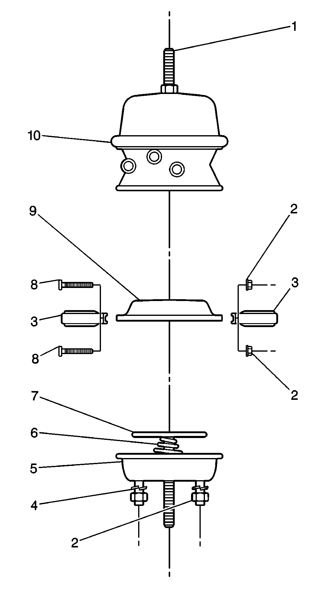
- Mark the adapter (10) and the service housing (5) in relation to the clamp ring assembly (3).
- Remove the air brake chamber clevis and the nut (2).
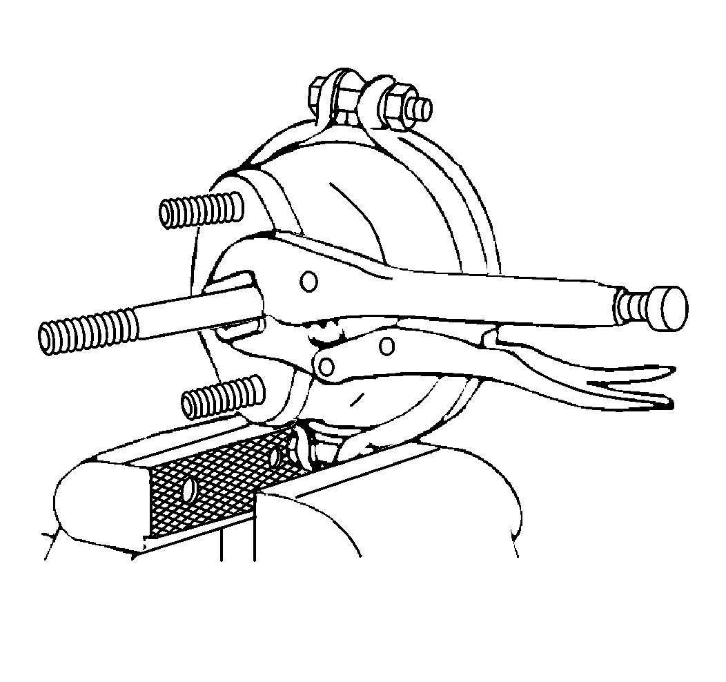
- Pull out the pushrod and use locking-type pliers to clamp the pushrod.
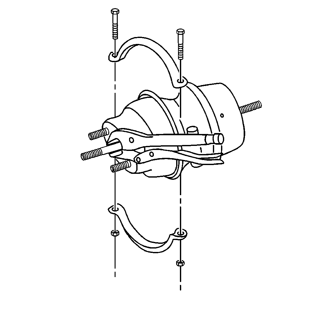
- Remove the nuts and the bolts.
- Remove the clamp ring assembly.
- Remove the service housing (5) from the adapter (6).
- Release the locking-type pliers from the pushrod.
- Remove the pushrod.
- Remove the return spring.
- Remove the diaphragm from the adapter.
- Inspect the inside of the service housing (5) for corrosion.
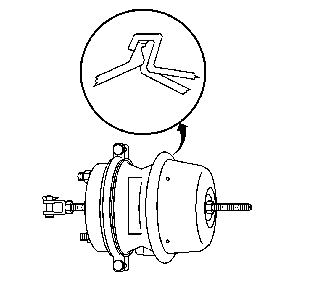
- Inspect the adapter (10) wall and the lip.
- Inspect the return spring (6).
- Inspect the pushrod (7).
- Inspect the clamp ring assembly (3).


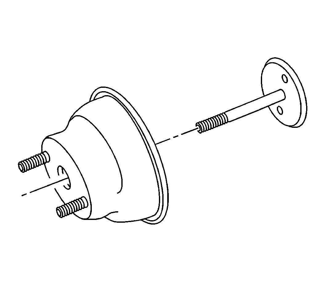
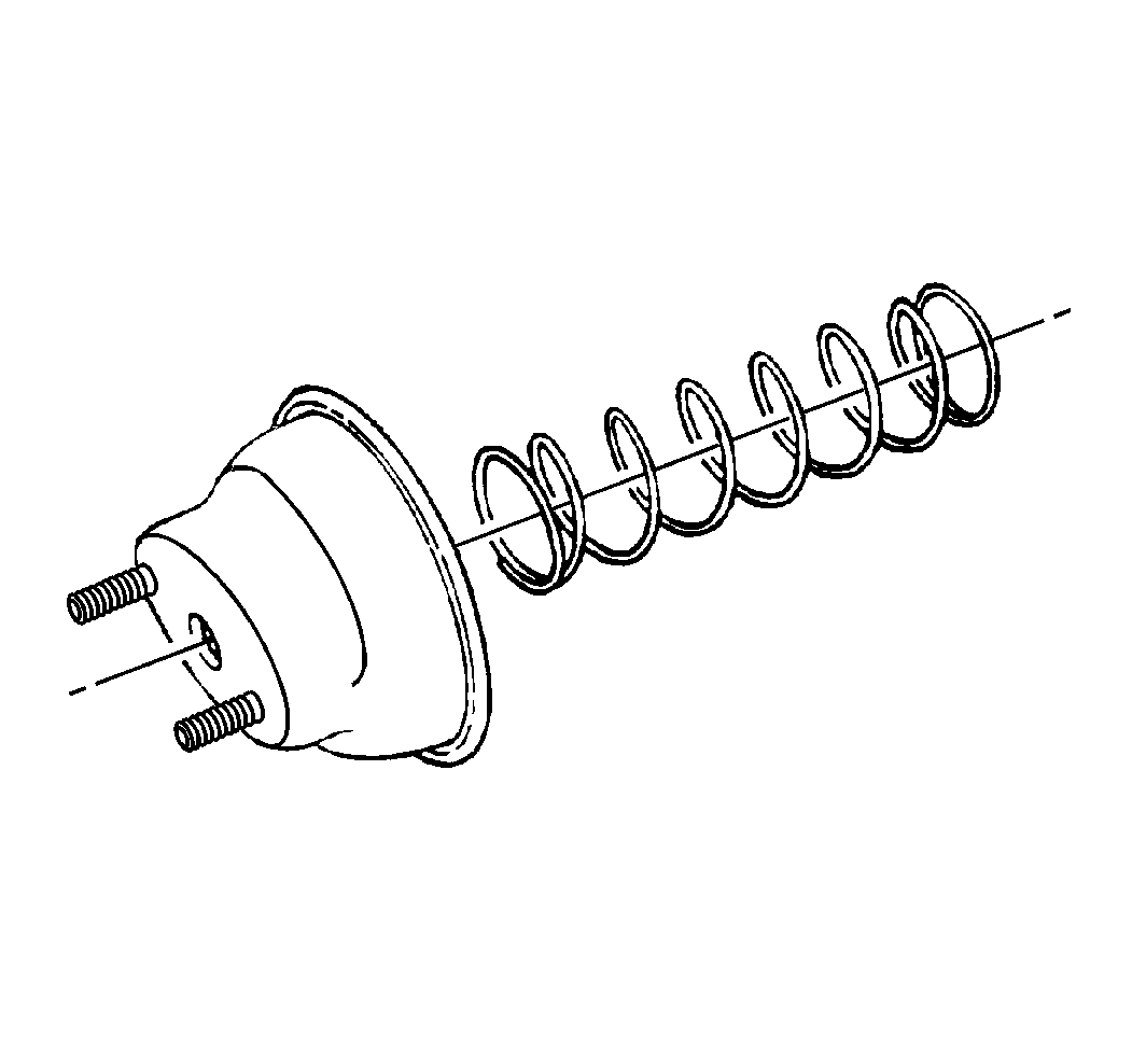
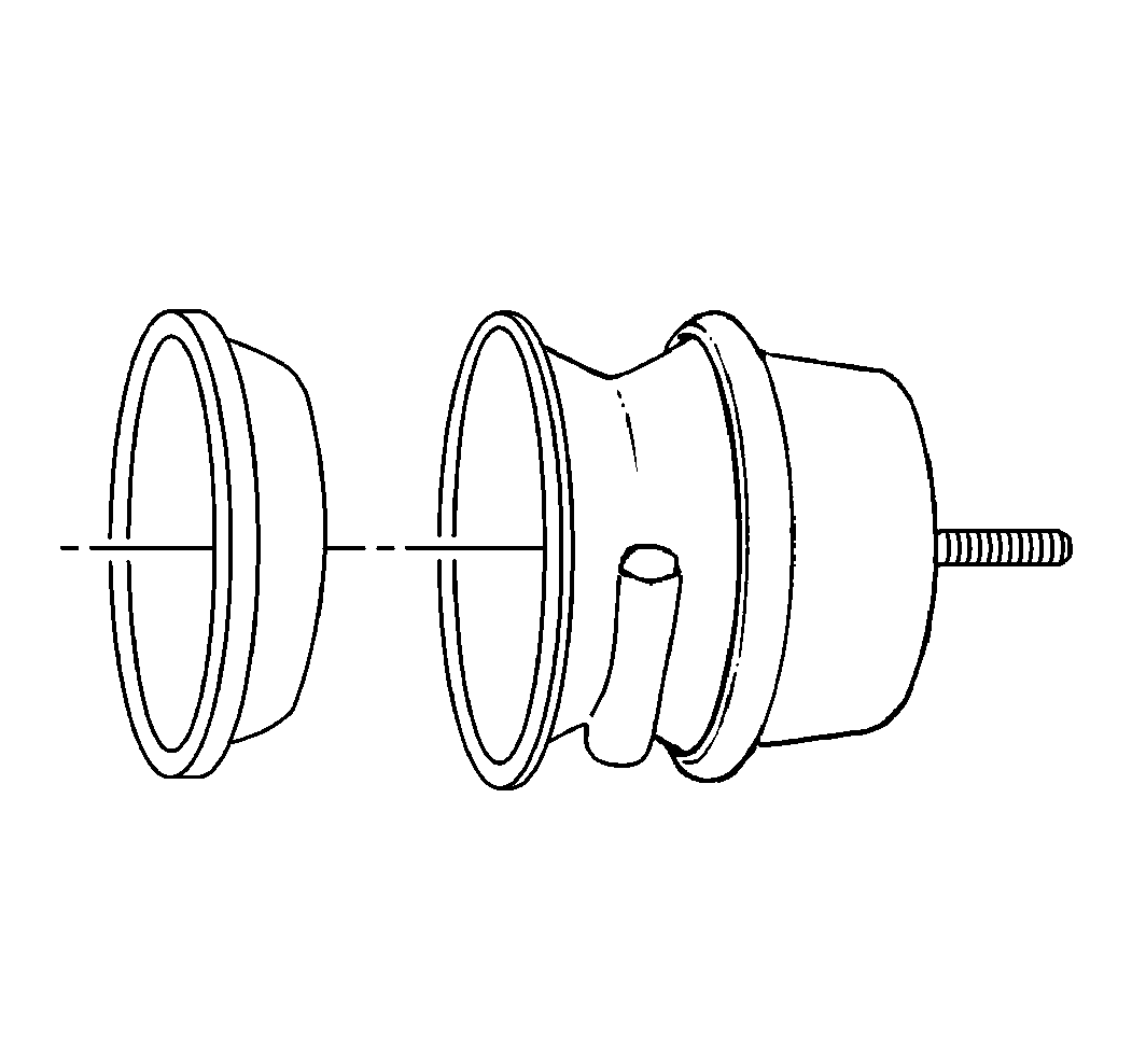

Important: Replace all worn and/or damaged parts.
Replace the service housing (5) if corrosion is found.
Assembly Procedure
- Install the return spring into the service housing.
- Install the pushrod into the service housing.
- Install the diaphragm into the adapter.
- Install the service housing (5) onto the adapter (10).
- Install the clamp ring assembly.
- Install the bolts and the nuts.
- Inspect the clamp assembly for the proper seating around the adapter and the service housing lip.
- Release the locking-type pliers.
- Loosely fit the nut and the spring brake chamber clevis to the pushrod.
- Install the nut (2) and the air brake chamber clevis to the pushrod (7).
Important: Compress the return spring and clamp the pushrod in place with locking-type pliers.


Important: Align the marks made during disassembly.
Notice: Refer to Fastener Notice in the Preface section.
Tighten
Tighten the nuts to 34 N·m (25 lb ft).


