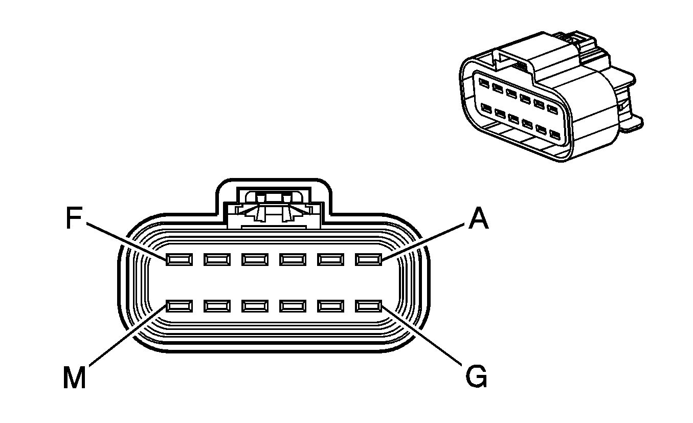
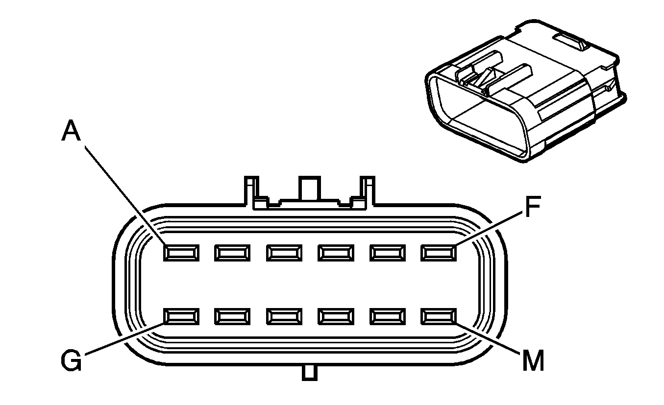
C100 Front Chassis Harness AUX WRG Connector to Upfitter Harness
|
|
Connector Part Information
| Connector Part Information
|
Pin | Wire Color | Circuit No. | Function | Pin | Wire Color | Circuit No. | Function |
|---|---|---|---|---|---|---|---|
A | WH/BK | DF57 | VSS Output Signal | A | -- | -- | Upfitter Usage |
B | D-BU | SA11 | Upfitter Pass-Through Circuit to Lower I/P Harness Connector C201 (Upfitter Connector), Pin F | B | -- | -- | Upfitter Usage |
C | YE | JA03 | Left Turn Signal Lamps Supply Voltage | C | -- | -- | Upfitter Usage |
D | D-GN | SA10 | Upfitter Pass-Through Circuit to Lower I/P Harness Connector C200, Pin 44 | D | -- | -- | Upfitter Usage |
E | WH | CA05 | Stop Lamp Supply Voltage | E | -- | -- | Upfitter Usage |
F | PK/D-BU | SA07 | Ignition 1 Voltage | F | -- | -- | Upfitter Usage |
G | BN | BA31 | Park Lamps Supply Voltage | G | -- | -- | Upfitter Usage |
H | BK | SX08 | Ground | H | -- | -- | Upfitter Usage |
J | D-BU/WH | SA19 | Rear Compartment Lamp Supply Voltage | J | -- | -- | Upfitter Usage |
K | D-GN | JA06 | Right Turn Signal Lamps Supply Voltage | K | -- | -- | Upfitter Usage |
L | L-GN | BA04 | Backup Lamp Supply Voltage | L | -- | -- | Upfitter Usage |
M | RD | SA04 | Battery Positive Voltage | M | -- | -- | Upfitter Usage |
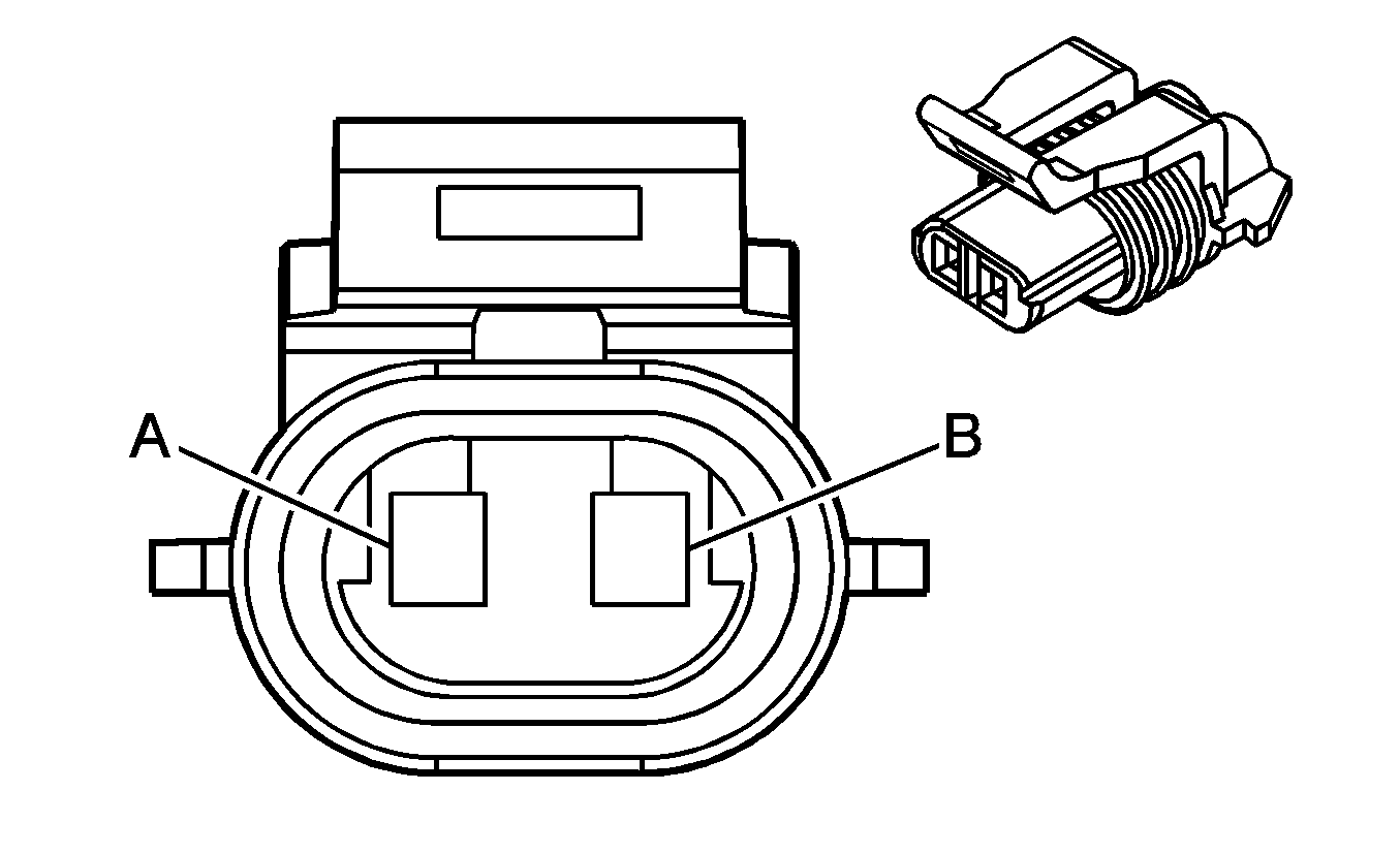
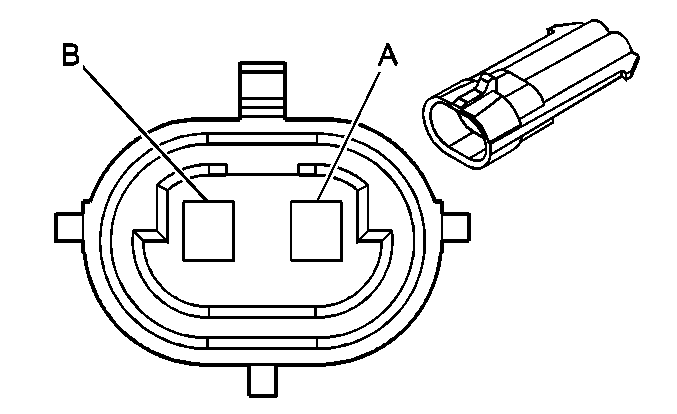
C101 Turn Signal Harness to Horn Harness (U08)
|
|
Connector Part Information
| Connector Part Information
|
Pin | Wire Color | Circuit No. | Function | Pin | Wire Color | Circuit No. | Function |
|---|---|---|---|---|---|---|---|
A | BK | 10 | Ground | A | BK | 150 | Ground |
B | D-GN/WH | 1 | Horn Control | B | D-GN | 29 | Horn Control |
C103 Front Chassis Harness TRANS OPT Connector to Upfitter Harness (Allison® LCT Automatic Transmission)
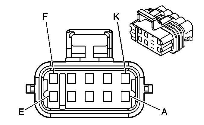
|

|
Connector Part Information
| Connector Part Information
|
Pin | Wire Color | Circuit No. | Function | Pin | Wire Color | Circuit No. | Function |
|---|---|---|---|---|---|---|---|
A | PU | OA24 | Engine Brake Enable Signal | A | -- | -- | Upfitter Usage |
B | YE | OA23 | A/T Neutral Signal | B | -- | -- | Upfitter Usage |
C | WH | OA20 | PTO Engaged Signal | C | -- | -- | Upfitter Usage |
D | -- | -- | Not Used | D | -- | -- | Upfitter Usage |
E | -- | -- | Not Used | E | -- | -- | Upfitter Usage |
F | BN | OA21 | Transmission Shift Inhibit Signal | F | -- | -- | Upfitter Usage |
G | -- | -- | Not Used | G | -- | -- | Upfitter Usage |
H | BK | OA25 | Low Reference | H | -- | -- | Upfitter Usage |
J | -- | -- | Not Used | J | -- | -- | Upfitter Usage |
K | D-BU | OA26 | Transmission Power Take-Off Enable Signal | K | -- | -- | Upfitter Usage |
C103 Front Chassis Harness TRANS OPT Connector to Upfitter Harness (Allison® MD Automatic Transmission)

|

|
Connector Part Information
| Connector Part Information
|
Pin | Wire Color | Circuit No. | Function | Pin | Wire Color | Circuit No. | Function |
|---|---|---|---|---|---|---|---|
A | PU | NF52 | Engine Brake Enable Signal | A | -- | -- | Upfitter Usage |
B | YE | NF53 | A/T Neutral Signal | B | -- | -- | Upfitter Usage |
C | WH | NF62 | PTO Enable Signal | C | -- | -- | Upfitter Usage |
D | YE | NF51 | Transmission Auxiliary Hold Signal | D | -- | -- | Upfitter Usage |
E | GY | NF50 | Transmission Shift Inhibit Signal | E | -- | -- | Upfitter Usage |
F | BN | NF48 | Transmission Shift Inhibit Signal | F | -- | -- | Upfitter Usage |
G | -- | -- | Not Used | G | -- | -- | Upfitter Usage |
H | BK | NF49 | Low Reference | H | -- | -- | Upfitter Usage |
J | BK | NF54 | Low Reference | J | -- | -- | Upfitter Usage |
K | -- | -- | Not Used | K | -- | -- | Upfitter Usage |
C104 Front Chassis Harness PTO Connector to Upfitter PTO Controls Harness (PTO)

|

|
Connector Part Information
| Connector Part Information
|
Pin | Wire Color | Circuit No. | Function | Pin | Wire Color | Circuit No. | Function |
|---|---|---|---|---|---|---|---|
A | -- | -- | Not Used | A | -- | -- | Upfitter Usage |
B | L-GN | WB12 | PTO Disable Signal | B | -- | -- | Upfitter Usage |
C | WH | WB07 | PTO On Switch Signal | C | -- | -- | Upfitter Usage |
D | BK | WY03 | Ground | D | -- | -- | Upfitter Usage |
E-F | -- | -- | Not Used | E-F | -- | -- | Upfitter Usage |
G | D-BU/RD | WB11 | PTO Status Signal | G | -- | -- | Upfitter Usage |
H | WH | WB10 | PTO Relay Output | H | -- | -- | Upfitter Usage |
J-K | -- | -- | Not Used | J-K | -- | -- | Upfitter Usage |
C105 Turn Signal Harness to Front Chassis Harness
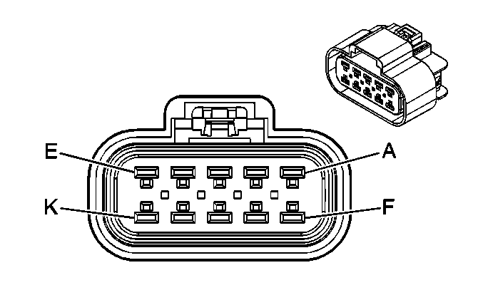
|
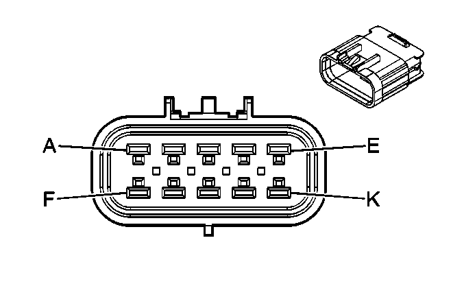
|
Connector Part Information
| Connector Part Information
|
Pin | Wire Color | Circuit No. | Function | Pin | Wire Color | Circuit No. | Function |
|---|---|---|---|---|---|---|---|
A | D-GN/RD | 7 | A/C Request Signal | A | D-GN/RD | HA25 | A/C Request Signal |
B | D-GN/OG | 6 | A/C Compressor Clutch Supply Voltage | B | D-GN/BK | HA26 | A/C Compressor Clutch Supply Voltage |
C | D-BU | 3 | Right Turn Signal Lamps Supply Voltage | C | D-BU | JA16 | Right Turn Signal Lamps Supply Voltage |
D | BK | 2 | Ground | D | BK | BX16 | Ground |
E | D-GN/WH | 1 | Horn Control | E | D-GN/WH | DA02 | Horn Control |
F | L-BU | 9 | A/C Compressor Relay Supply Voltage | F | L-BU | HA06 | A/C Compressor Relay Supply Voltage |
G | D-GN/WH | 8 | Condenser Relay Control | G | D-GN/WH | HA04 | Condenser Relay Control |
H | -- | -- | Not Used | H | -- | -- | Not Used |
J | BN | 5 | Park Lamp Supply Voltage | J | BN | BA29 | Park Lamp Supply Voltage |
K | L-BU | 4 | Left Turn Signal Lamps Supply Voltage | K | L-BU | JA12 | Left Turn Signal Lamps Supply Voltage |
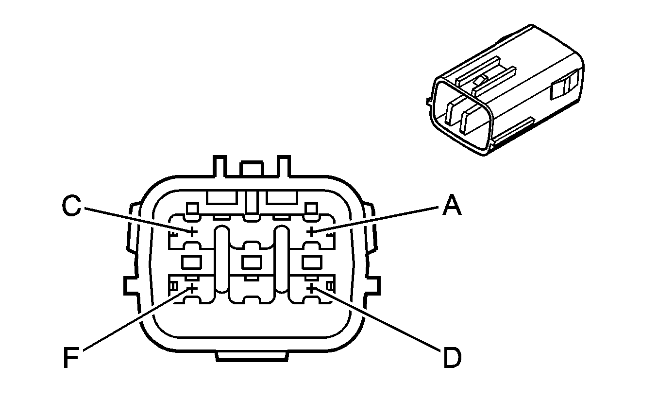
C106 Front Chassis Harness to Upfitter Remote PTO Harness (PTO)
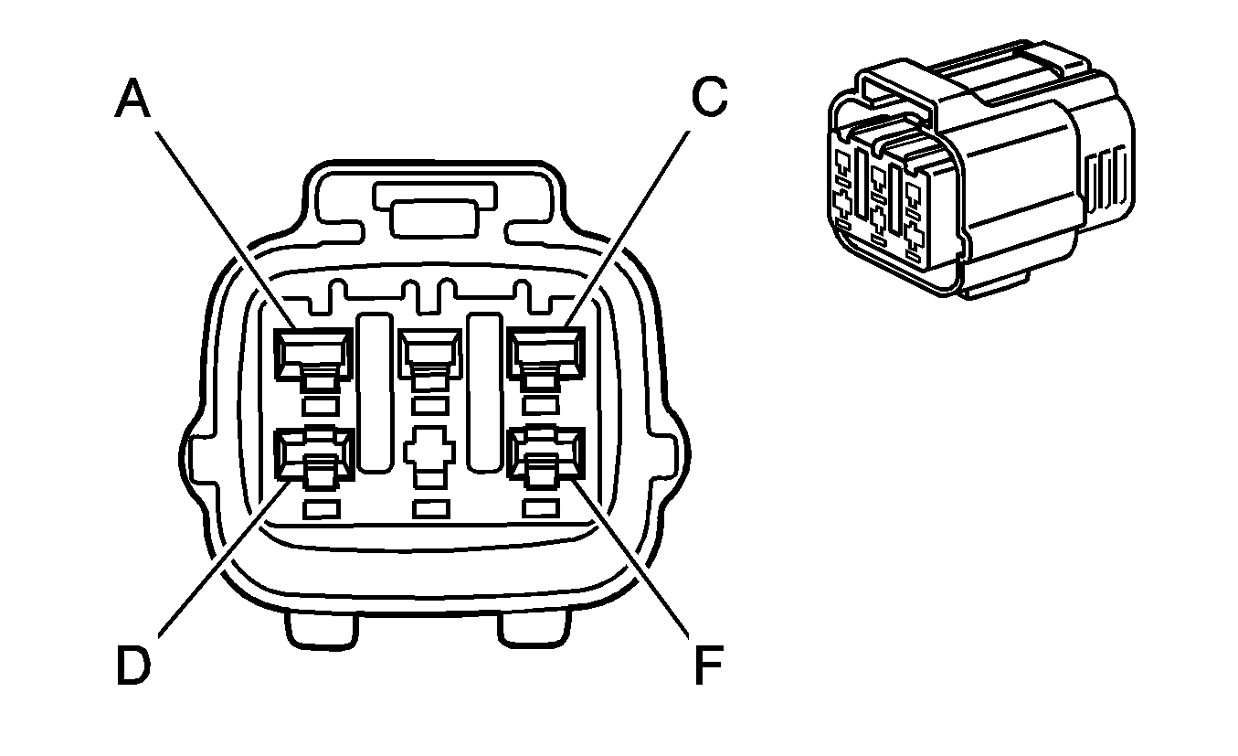
|
|
Connector Part Information
| Connector Part Information
|
Pin | Wire Color | Circuit No. | Function | Pin | Wire Color | Circuit No. | Function |
|---|---|---|---|---|---|---|---|
A | BK/YE | DF05 | PTO Set Switch Signal - Remote | A | -- | -- | Upfitter Usage |
B | WH/RD | DF06 | PTO Resume Switch Signal - Remote | B | -- | -- | Upfitter Usage |
C | D-GN/WH | DF07 | PTO Set Switch Signal B - Remote | C | -- | -- | Upfitter Usage |
D | RD/BK | DF08 | PTO Disable Switch Signal - Remote | D | -- | -- | Upfitter Usage |
E | BK/WH | DF09 | PTO Set Switch Signal A - Remote | E | -- | -- | Upfitter Usage |
F | BK | CU05 | Ground | F | -- | -- | Upfitter Usage |
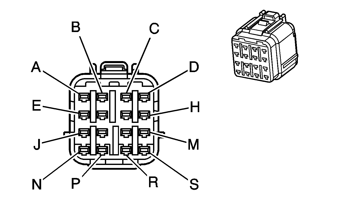
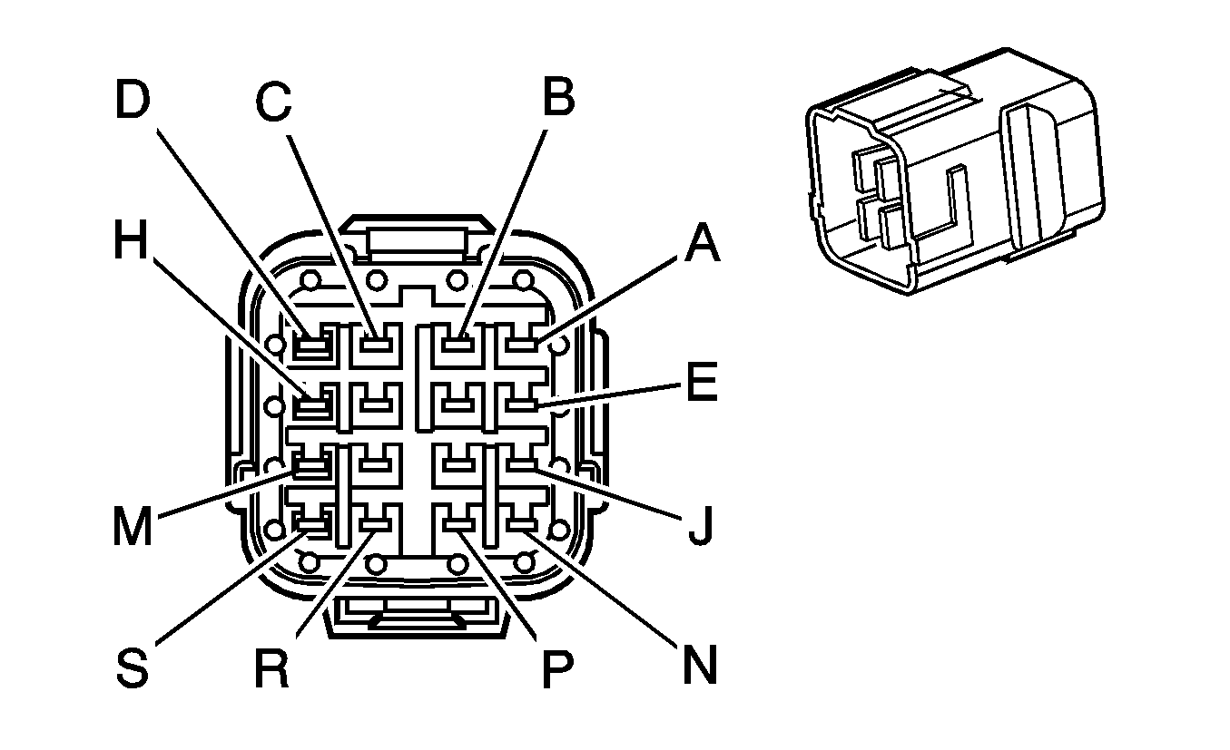
C108 Transmission Cab Harness to Front Chassis Harness (Allison® LCT Automatic Transmission)
|
|
Connector Part Information
| Connector Part Information
|
Pin | Wire Color | Circuit No. | Function | Pin | Wire Color | Circuit No. | Function |
|---|---|---|---|---|---|---|---|
A | BN | OA21 | Transmission Shift Inhibit Signal | A | BN | OA21 | Transmission Shift Inhibit Signal |
B | WH | OA20 | Transmission Power Take-Off Enable Signal | B | WH | OA20 | Transmission Power Take-Off Enable Signal |
C | GY/WH | OA18 | Drain Wire | C | GY | OA18 | Drain Wire |
D | WH | OA16 | Signal High - Rear | D | WH | OA16 | Signal High - Rear |
E | BK | OA25 | Low Reference | E | BK | OA25 | Low Reference |
F | PU | OA24 | Engine Brake Enable Signal | F | PU | OA24 | Engine Brake Enable Signal |
G | YE | OA23 | A/T Neutral Signal | G | YE | OA23 | A/T Neutral Signal |
H | -- | -- | Not Used | H | -- | -- | Not Used |
J | D-BU/WH | OA29 | Transmission Turbine Speed Switch Low Reference | J | D-BU/WH | OA29 | Transmission Turbine Speed Switch Low Reference |
K | BK/D-BU | OA28 | AT ISS High Signal | K | BK/RD | OA28 | AT ISS High Signal |
L | WH/D-BU | OA27 | AT ISS Low Signal | L | WH/D-BU | OA27 | AT ISS Low Signal |
M | D-BU | OA26 | PTO Control | M | D-BU | OA26 | PTO Control |
N | PK/ BK | OA33 | PC Solenoid Valve Low Control (Sol A) | N | RD/BK | OA33 | PC Solenoid Valve Low Control (Sol A) |
P | BK/D-BU | OA32 | VSS High Signal | P | D-BU/OG | OA32 | VSS High Signal |
R | WH/D-BU | OA31 | VSS Low Signal | R | WH/RD | OA31 | VSS Low Signal |
S | D-BU | OA30 | Transmission Turbine Speed Switch Signal | S | D-BU | OA30 | Transmission Turbine Speed Switch Signal |
C108 Transmission Cab Harness to Front Chassis Harness (Allison® MD Automatic Transmission)

|

|
Connector Part Information
| Connector Part Information
|
Pin | Wire Color | Circuit No. | Function | Pin | Wire Color | Circuit No. | Function |
|---|---|---|---|---|---|---|---|
A | D-BU/WH | NF27 | VSS Low Signal | A | D-BU/WH | NF27 | VSS Low Signal |
B | BK/D-BU | NF26 | AT ISS High Signal | B | BN | NF26 | AT ISS High Signal |
C | WH/D-BU | NF25 | AT ISS Low Signal | C | WH/D-BU | NF25 | AT ISS Low Signal |
D | L-GN | NF22 | Backup Lamp Relay Output | D | L-GN | NF22 | Backup Lamp Relay Output |
E | L-BU | NF31 | 12-Volt Reference | E | D-BU | NF31 | 12-Volt Reference |
F | BK/D-BU | NF30 | Transmission Turbine Speed Switch Signal | F | D-BU/OG | NF30 | Transmission Turbine Speed Switch Signal |
G | WH/D-BU | NF29 | Transmission Turbine Speed Switch Low Reference | G | WH/RD | NF29 | Transmission Turbine Speed Switch Low Reference |
H | D-BU | NF28 | VSS High Signal | H | D-BU | NF28 | VSS High Signal |
J | WH | NF35 | Shift Solenoid Valve E Control | J | WH | NF35 | Shift Solenoid Valve E Control |
K | PU | NF34 | Shift Solenoid Valve B Control | K | PU | NF34 | Shift Solenoid Valve B Control |
L | WH | NF33 | 12-Volt Reference | L | WH | NF33 | 12-Volt Reference |
M | WH | NF32 | Shift Solenoid Valve F Control | M | WH | NF32 | Shift Solenoid Valve F Control |
N | L-GN | NF39 | 12-Volt Reference | N | L-GN | NF39 | 12-Volt Reference |
P | YE/BK | NF38 | Shift Solenoid Valve D Control | P | YE/BK | NF38 | Shift Solenoid Valve D Control |
R | OG | NF37 | Shift Solenoid Valve A Control | R | RD | NF37 | Shift Solenoid Valve A Control |
S | RD | NF36 | 12-Volt Reference | S | RD | NF36 | 12-Volt Reference |
C109 Transmission Cab Harness to Front Chassis Harness (Allison® LCT Automatic Transmission)

|

|
Connector Part Information
| Connector Part Information
|
Pin | Wire Color | Circuit No. | Function | Pin | Wire Color | Circuit No. | Function |
|---|---|---|---|---|---|---|---|
A | YE/BK | OA37 | Shift Solenoid Valve D Control | A | YE/BK | OA37 | Shift Solenoid Valve D Control |
B | PU | OA36 | Shift Solenoid Valve C Control | B | PU | OA36 | Shift Solenoid Valve C Control |
C | BN | OA35 | 12-Volt Reference | C | BN | OA35 | 12-Volt Reference |
D | BN/WH | OA34 | PC Solenoid Valve Low Control (Sol B) | D | BK/WH | OA34 | PC Solenoid Valve Low Control (Sol B) |
E | PK | OA41 | Transmission Fluid Pressure Switch Signal C | E | PK | OA41 | Transmission Fluid Pressure Switch Signal C |
F | WH | OA40 | TCC PWM Solenoid Valve Control | F | WH | OA40 | TCC PWM Solenoid Valve Control |
G | D-GN/WH | OA39 | Line Pressure Control Solenoid Valve High Control | G | D-GN/WH | OA39 | Line Pressure Control Solenoid Valve High Control |
H | OG/WH | OA38 | Shift Solenoid Valve E Control | H | RD/WH | OA38 | Shift Solenoid Valve E Control |
J | YE/BK | OA45 | Transmission Fluid Temperature Sensor Signal | J | YE/BK | OA45 | Transmission Fluid Temperature Sensor Signal |
K | L-GN/BK | OA44 | Transmission Fluid Pressure Switch Signal R | K | L-GN | OA44 | Transmission Fluid Pressure Switch Signal R |
L | RD | OA43 | Transmission Fluid Pressure Switch Signal E | L | RD | OA43 | Transmission Fluid Pressure Switch Signal E |
M | D-BU | OA42 | Transmission Fluid Pressure Switch Signal D | M | D-BU | OA42 | Transmission Fluid Pressure Switch Signal D |
N | D-BU/WH | OA49 | PC Solenoid Valve Low Control (Sol A) | N | D-BU/WH | OA49 | PC Solenoid Valve Low Control (Sol A) |
P | RD/BK | OA48 | PC Solenoid Valve High Control (Sol A) | P | RD/BK | OA48 | PC Solenoid Valve High Control (Sol A) |
R | YE | OA47 | Trans ID | R | YE | OA47 | Trans ID |
S | BK | OA46 | Low Reference | S | BK | OA46 | Low Reference |
C109 Transmission Cab Harness to Front Chassis Harness (Allison® MD Automatic Transmission)

|

|
Connector Part Information
| Connector Part Information
|
Pin | Wire Color | Circuit No. | Function | Pin | Wire Color | Circuit No. | Function |
|---|---|---|---|---|---|---|---|
A | RD/BK | NF43 | Trans ID | A | RD/BK | NF43 | Trans ID |
B | RD | NF42 | Transmission Fluid Pressure Switch Signal C3 | B | RD | NF42 | Transmission Fluid Pressure Switch Signal C3 |
C | WH | NF41 | Shift Solenoid Valve G Control | C | WH | NF41 | Shift Solenoid Valve G Control |
D | PU | NF40 | Shift Solenoid Valve C Control | D | PU | NF40 | Shift Solenoid Valve C Control |
E | YE/BK | NF47 | Transmission Fluid Temperature Sensor Signal | E | YE/BK | NF47 | Transmission Fluid Temperature Sensor Signal |
F | BK | NF46 | Low Reference | F | BK | NF46 | Low Reference |
G | WH | NF45 | Transmission Oil Level Sensor Signal | G | WH | NF45 | Transmission Oil Level Sensor Signal |
H | D-GN | NF44 | 5-Volt Reference | H | D-GN | NF44 | 5-Volt Reference |
J | PU | NF52 | Engine Brake Enable Signal | J | PU | NF52 | Engine Brake Enable Signal |
K | YE | NF51 | Transmission Auxiliary Hold Signal | K | YE | NF51 | Transmission Auxiliary Hold Signal |
L | GY | NF50 | Transmission Fluid Temperature Sensor Signal | L | GY | NF50 | Transmission Fluid Temperature Sensor Signal |
M | BN | NF48 | Transmission Shift Inhibit Signal | M | BN | NF48 | Transmission Shift Inhibit Signal |
N | BK | NU01 | Ground | N | BK | NU01 | Ground |
P | WH | NF62 | Transmission Power Take-Off Enable Signal | P | WH | NF62 | Transmission Power Take-Off Enable Signal |
R | BK | NF54 | Low Reference | R | BK | NF54 | Low Reference |
S | YE | NF53 | A/T Neutral Signal | S | YE | NF53 | A/T Neutral Signal |
C110 Transmission Cab Harness to Front Chassis Harness (Allison® LCT Automatic Transmission)

|

|
Connector Part Information
| Connector Part Information
|
Pin | Wire Color | Circuit No. | Function | Pin | Wire Color | Circuit No. | Function |
|---|---|---|---|---|---|---|---|
A | YE | OA52 | Transmission Range Switch Signal B | A | YE | OA52 | Transmission Range Switch Signal B |
B | BK/WH | OA51 | Transmission Range Switch Signal A | B | BK/WH | OA51 | Transmission Range Switch Signal A |
C | D-BU/OG | OA50 | Transmission Mainline Pressure Solenoid Control | C | D-BU/OG | OA50 | Transmission Mainline Pressure Solenoid Control |
D | BK/OG | OX01 | Ground | D | BK | OX01 | Ground |
E | WH | OA54 | Transmission Range Switch Signal P | E | WH | OA54 | Transmission Range Switch Signal P |
F | GY | OA53 | Transmission Range Switch Signal C | F | GY | OA53 | Transmission Range Switch Signal C |
C111 Front Chassis Harness to Engine Harness

|

|
Connector Part Information
| Connector Part Information
|
Pin | Wire Color | Circuit No. | Function | Pin | Wire Color | Circuit No. | Function |
|---|---|---|---|---|---|---|---|
A | -- | -- | Not Used | A | RD | B23 | Not Used |
B | -- | -- | Not Used | B | BK | B11 | Not Used |
C | BK/RD | DF15 | Ignition 1 Voltage | C | RD | IC02 | Ignition 1 Voltage |
D-E | -- | -- | Not Used | D-E | -- | -- | Not Used |
F | D-BU/BK | DF72 | Fuel Heater Supply Voltage | F | RD | IC35 | Fuel Heater Supply Voltage |
C115 Engine Chassis Harness to Front Chassis Harness (Allison® LCT Automatic Transmission)

|

|
Connector Part Information
| Connector Part Information
|
Pin | Wire Color | Circuit No. | Function | Pin | Wire Color | Circuit No. | Function |
|---|---|---|---|---|---|---|---|
A | TN | PA29 | Charge Indicator Control | A | RD | PA29 | Charge Indicator Control |
B | TN | PA20 | Ignition 1 Voltage | B | BN/WH | PA20 | Ignition 1 Voltage |
C | RD/D-BU | DF59 | Generator Field Duty Cycle Signal | C | RD/BK | DF59 | Generator Field Duty Cycle Signal |
D | BK | HX02 | Ground | D | BK | HX02 | Ground |
E | D-BU/RD | OA50 | Transmission Mainline Pressure Solenoid Control | E | D-BU/OG | OA50 | Transmission Mainline Pressure Solenoid Control |
F | D-GN/BK | HA26 | A/C Compressor Clutch Supply Voltage | F | D-GN/BK | HA26 | A/C Compressor Clutch Supply Voltage |
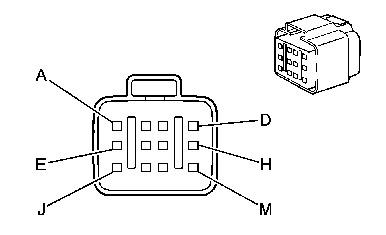
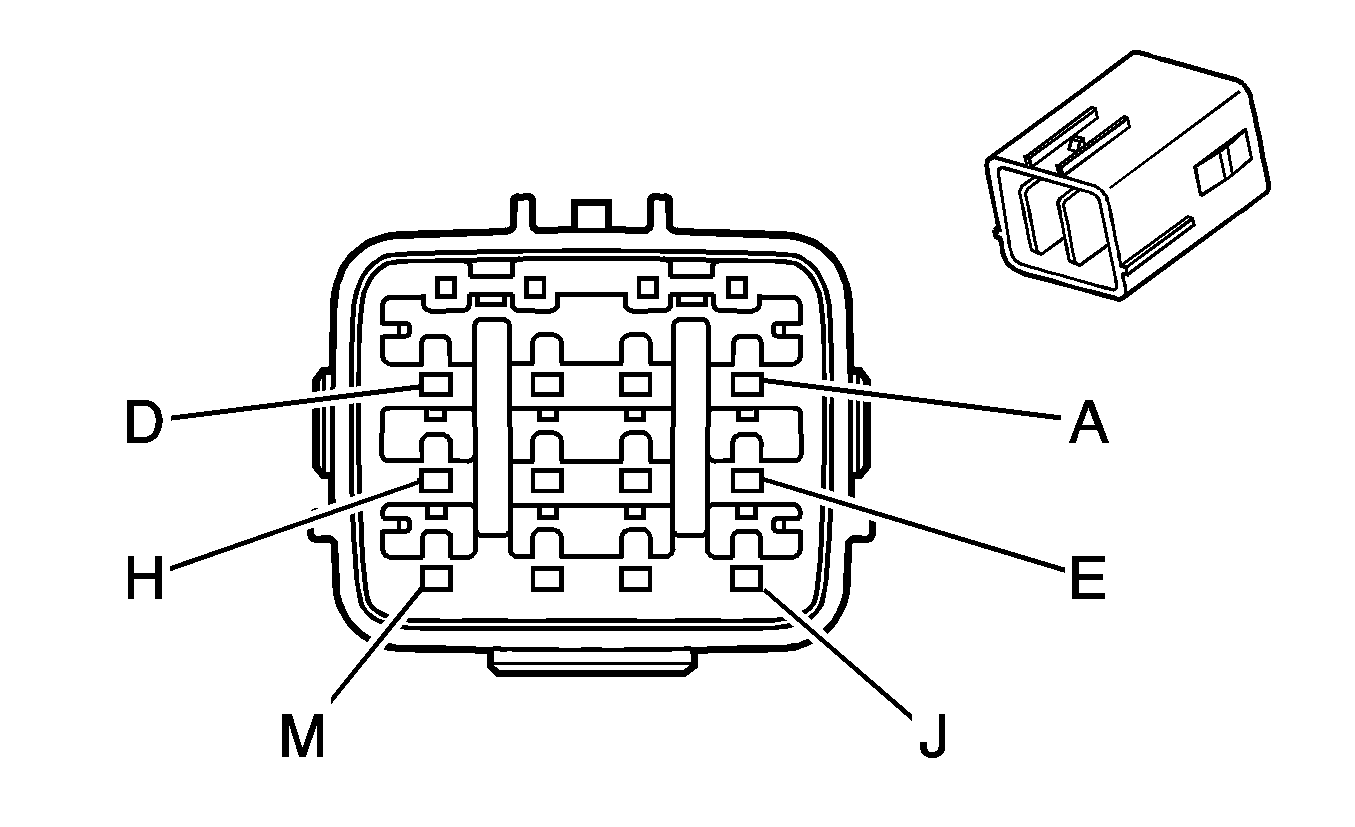
C115 Engine Chassis Harness to Front Chassis Harness (Allison® MD Automatic Transmission)
|
|
Connector Part Information
| Connector Part Information
|
Pin | Wire Color | Circuit No. | Function | Pin | Wire Color | Circuit No. | Function |
|---|---|---|---|---|---|---|---|
A | WH/RD | NF41 | Shift Solenoid G Valve Control | A | WH | NF41 | Shift Solenoid G Valve Control |
B | RD | NF42 | Transmission Fluid Pressure Switch Signal C3 | B | RD | NF42 | Transmission Fluid Pressure Switch Signal C3 |
C | RD/BK | NF43 | Trans ID | C | RD/BK | NF43 | Trans ID |
D | D-GN | NF44 | 5-Volt Reference | D | D-GN | NF44 | 5-Volt Reference |
E | WH | NF45 | Transmission Oil Level Sensor Signal | E | WH | NF45 | Transmission Oil Level Sensor Signal |
F | YE | NF47 | TFT Sensor Signal | F | YE/BK | NF47 | TFT Sensor Signal |
G | BK | NF46 | Low Reference | G | BK | NF46 | Low Reference |
H | BK | HX02 | Ground | H | BK | HX02 | Ground |
J | BN | PA29 | Charge Indicator Control | J | RD | PA29 | Charge Indicator Control |
K | BN | PA20 | Ignition 1 Voltage | K | BN/WH | PA20 | Ignition 1 Voltage |
L | RD/D-BU | DF59 | Generator Field Duty Cycle Signal | L | RD/BK | DF59 | Generator Field Duty Cycle Signal |
M | D-GN/BK | HA26 | A/C Compressor Clutch Supply Voltage | M | D-GN/BK | HA26 | A/C Compressor Clutch Supply Voltage |
C115 Engine Chassis Harness to Front Chassis Harness (Manual Transmission)

|

|
Connector Part Information
| Connector Part Information
|
Pin | Wire Color | Circuit No. | Function | Pin | Wire Color | Circuit No. | Function |
|---|---|---|---|---|---|---|---|
A | WH | DF38 | VSS High Signal | A | WH | DF38 | VSS High Signal |
B | BK | DF39 | VSS Low Signal | B | BK | DF39 | VSS Low Signal |
C | BK/YE | DF42 | Ground | C | BK/YE | DF42 | Ground |
D | RD | BA01 | Ignition 1 Voltage | D | PK | BA01 | Ignition 1 Voltage |
E | D-GN | BA02 | Backup Lamp Supply Voltage | E | L-GN | BA02 | Backup Lamp Supply Voltage |
F | BN | PA29 | Charge Indicator Control | F | RD | PA29 | Charge Indicator Control |
G | BN | PA20 | Ignition 1 Voltage | G | BN/WH | PA20 | Ignition 1 Voltage |
H | RD/D-BU | DF59 | Generator Field Duty Cycle Signal | H | D-GN/RD | DF59 | Generator Field Duty Cycle Signal |
J | -- | -- | Not Used | J | -- | -- | Not Used |
K | BK | HX02 | Ground | K | BK | HX02 | Ground |
L | -- | -- | Not Used | L | -- | -- | Not Used |
M | D-GN/BK | HA26 | A/C Compressor Clutch Supply Voltage | M | D-GN/BK | HA26 | A/C Compressor Clutch Supply Voltage |
C116 Front Chassis Harness to Engine Chassis Harness (Allison® LCT Automatic Transmission)

|

|
Connector Part Information
| Connector Part Information
|
Pin | Wire Color | Circuit No. | Function | Pin | Wire Color | Circuit No. | Function |
|---|---|---|---|---|---|---|---|
A | D-BU | OA30 | Transmission Turbine Speed Switch Signal | A | D-BU/RD | OA30 | Transmission Turbine Speed Switch Signal |
B | D-BU/WH | OA29 | Transmission Turbine Speed Switch Low Reference | B | WH/RD | OA29 | Transmission Turbine Speed Switch Low Reference |
C | BK/RD | OA28 | AT ISS High Signal | C | BK/RD | OA28 | AT ISS High Signal |
D | WH/D-BU | OA27 | AT ISS Low Signal | D | WH/BK | OA27 | AT ISS Low Signal |
E | BK/WH | OA34 | PC Solenoid Valve High Control (Sol B) | E | BK/WH | OA34 | PC Solenoid Valve High Control (Sol B) |
F | RD/BK | OA33 | PC Solenoid Valve Low Control (Sol B) | F | RD/BK | OA33 | PC Solenoid Valve Low Control (Sol B) |
G | D-BU/OG | OA32 | VSS High Signal | G | BK | OA32 | VSS High Signal |
H | WH/OG | OA31 | VSS Low Signal | H | RD/D-BU | OA31 | VSS Low Signal |
J | RD/WH | OA38 | Shift Solenoid E Valve Control | J | RD/WH | OA38 | Shift Solenoid E Valve Control |
K | YE/BK | OA37 | Shift Solenoid D Valve Control | K | YE | OA37 | Shift Solenoid D Valve Control |
L | PU | OA36 | Shift Solenoid C Valve Control | L | BK/D-BU | OA36 | Shift Solenoid C Valve Control |
M | BN | OA35 | 12-Volt Reference | M | BN | OA35 | 12-Volt Reference |
N | D-BU | OA42 | Transmission Fluid Pressure Switch Signal D | N | D-BU/WH | OA42 | Transmission Fluid Pressure Switch Signal D |
P | PK | OA41 | Transmission Fluid Pressure Switch Signal C | P | RD | OA41 | Transmission Fluid Pressure Switch Signal C |
R | WH | OA40 | TCC PWM Solenoid Valve Control | R | WH | OA40 | TCC PWM Solenoid Valve Control |
S | D-GN/WH | OA39 | Line Pressure Control Solenoid Valve High Control | S | D-GN/WH | OA39 | Line Pressure Control Solenoid Valve High Control |
C116 Front Chassis Harness to Engine Chassis Harness (Allison® MD Automatic Transmission)

|

|
Connector Part Information
| Connector Part Information
|
Pin | Wire Color | Circuit No. | Function | Pin | Wire Color | Circuit No. | Function |
|---|---|---|---|---|---|---|---|
A | D-BU | NF28 | VSS High Signal | A | D-BU/RD | NF28 | VSS High Signal |
B | D-BU/WH | NF27 | VSS Low Signal | B | WH/RD | NF27 | VSS Low Signal |
C | BK/RD | NF26 | AT ISS High Signal | C | BK/WH | NF26 | AT ISS High Signal |
D | WH/D-BU | NF25 | AT ISS Low Signal | D | WH/RD | NF25 | AT ISS Low Signal |
E | WH | NF32 | Shift Solenoid F Valve Control | E | WH/D-BU | NF32 | Shift Solenoid F Valve Control |
F | D-BU | NF31 | 12-Volt Reference | F | D-BU | NF31 | 12-Volt Reference |
G | D-BU/OG | NF30 | Transmission Turbine Speed Switch Signal | G | BK/WH | NF30 | Transmission Turbine Speed Switch Signal |
H | WH/RD | NF29 | Transmission Turbine Speed Switch Low Reference | H | RD/YE | NF29 | Transmission Turbine Speed Switch Low Reference |
J | RD | NF36 | 12-Volt Reference | J | RD/D-BU | NF36 | 12-Volt Reference |
K | WH | NF35 | Shift Solenoid E Valve Control | K | WH/D-GN | NF35 | Shift Solenoid E Valve Control |
L | PU | NF34 | Shift Solenoid B Valve Control | L | D-BU/RD | NF34 | Shift Solenoid B Valve Control |
M | WH | NF33 | 12-Volt Reference | M | WH/BK | NF33 | 12-Volt Reference |
N | PU | NF40 | Shift Solenoid C Valve Control | N | D-BU/WH | NF40 | Shift Solenoid C Valve Control |
P | L-GN | NF39 | 12-Volt Reference | P | D-GN/RD | NF39 | 12-Volt Reference |
R | YE/BK | NF38 | Shift Solenoid D Valve Control | R | YE/RD | NF38 | Shift Solenoid D Valve Control |
S | RD | NF37 | Shift Solenoid A Valve Control | S | RD/WH | NF37 | Shift Solenoid A Valve Control |
C117 Front Chassis Harness to Engine Chassis Harness (Allison® LCT Automatic Transmission)

|

|
Connector Part Information
| Connector Part Information
|
Pin | Wire Color | Circuit No. | Function | Pin | Wire Color | Circuit No. | Function |
|---|---|---|---|---|---|---|---|
A | BK | OA46 | Low Reference | A | BK/WH | OA46 | Low Reference |
B | YE/BK | OA45 | TFT Sensor Signal | B | YE/D-BU | OA45 | TFT Sensor Signal |
C | L-GN | OA44 | Transmission Fluid Pressure Switch Signal R | C | D-GN | OA44 | Transmission Fluid Pressure Switch Signal R |
D | RD | OA43 | Transmission Fluid Pressure Switch Signal E | D | RD/D-BU | OA43 | Transmission Fluid Pressure Switch Signal E |
E | BK/WH | OA51 | Transmission Range Switch Signal A | E | BK/WH | OA51 | Transmission Range Switch Signal A |
F | D-BU/WH | OA49 | PC Solenoid Valve Low Control (Sol A) | F | D-BU | OA49 | PC Solenoid Valve Low Control (Sol A) |
G | RD/BK | OA48 | PC Solenoid Valve High Control (Sol A) | G | RD/BK | OA48 | PC Solenoid Valve High Control (Sol A) |
H | YE | OA47 | Trans ID | H | YE/RD | OA47 | Trans ID |
J | PK | OA58 | Ignition 1 Voltage | J | RD | OA58 | Ignition 1 Voltage |
K | WH | OA54 | Transmission Range Switch Signal P | K | WH | OA54 | Transmission Range Switch Signal P |
L | GY | OA53 | Transmission Range Switch Signal C | L | BN | OA53 | Transmission Range Switch Signal C |
M | YE | OA52 | Transmission Range Switch Signal B | M | YE | OA52 | Transmission Range Switch Signal B |
N | BK | OX05 | Ground | N | BK | OX06 | Ground |
P | YE | OA56 | PNP/Clutch Start Switch Signal | P | RD | OA56 | PNP/Clutch Start Switch Signal |
R | L-GN | OA59 | Backup Lamp Supply Voltage | R | D-GN/RD | OA59 | Backup Lamp Supply Voltage |
S | YE/D-GN | OA55 | Ignition 0 Voltage | S | YE/D-GN | OA55 | Ignition 0 Voltage |
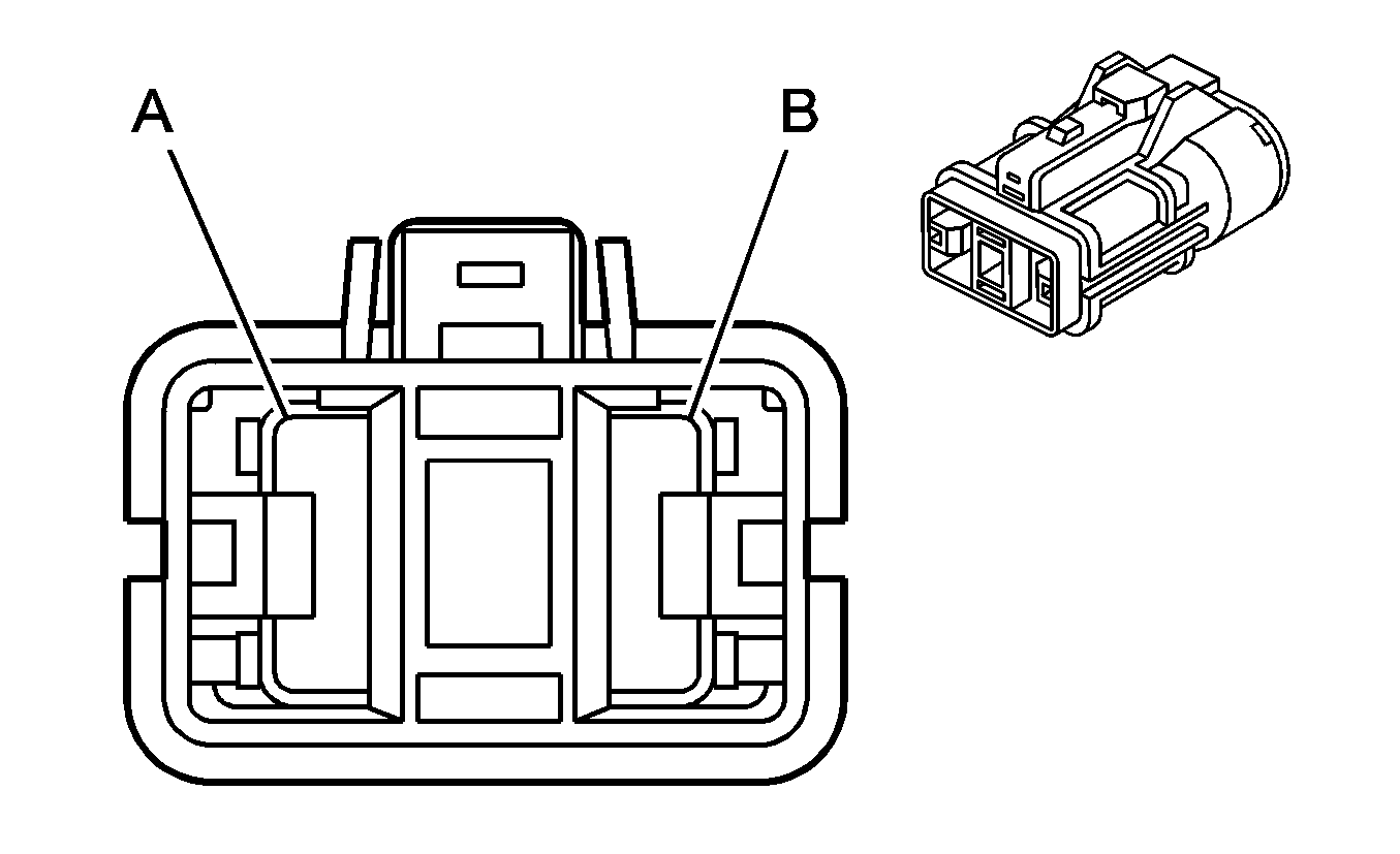
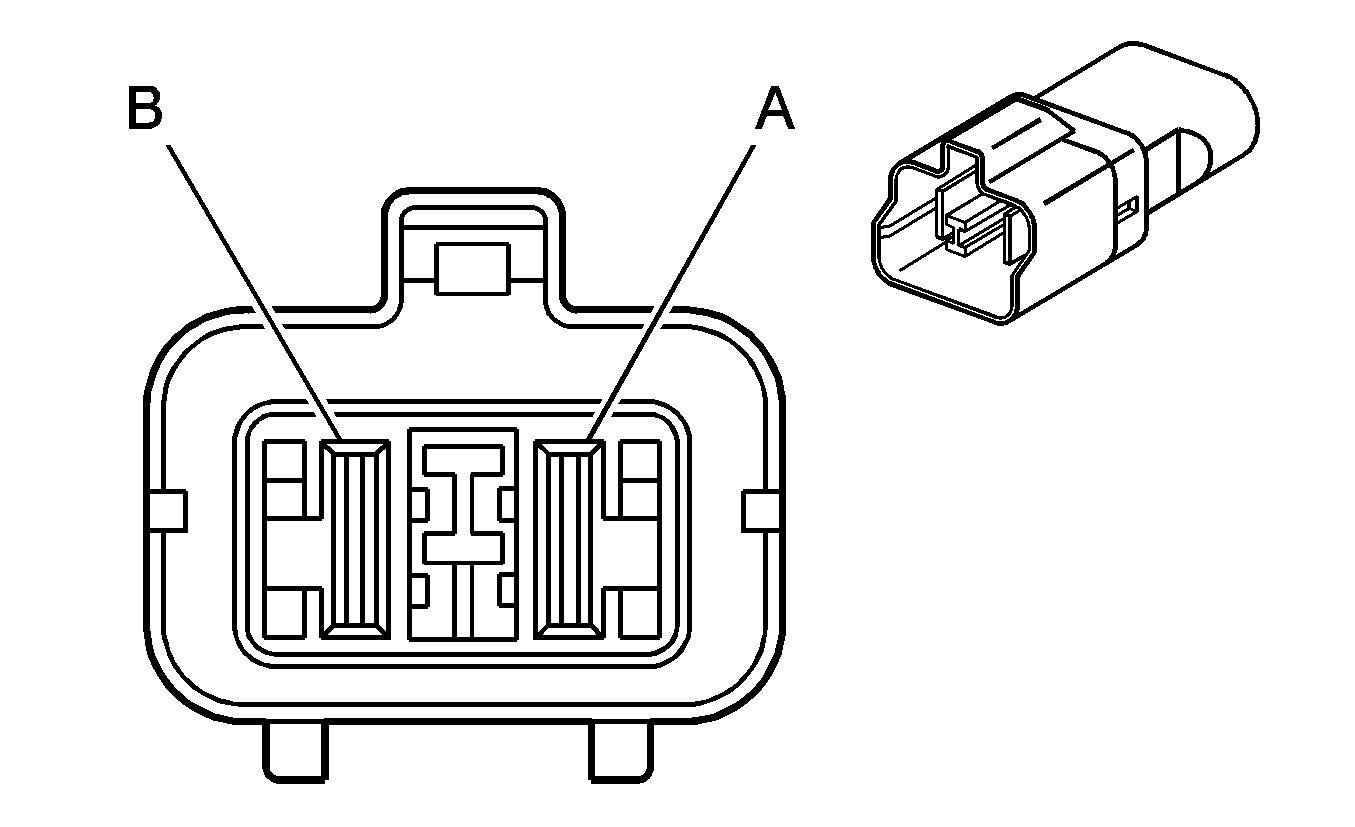
C118 Front Chassis Harness to Engine Harness
|
|
Connector Part Information
| Connector Part Information
|
Pin | Wire Color | Circuit No. | Function | Pin | Wire Color | Circuit No. | Function |
|---|---|---|---|---|---|---|---|
A | RD | HB02 | Glow Plug Supply Voltage | A | RD | IC33 | Glow Plug Supply Voltage |
B | -- | -- | Not Used | B | -- | -- | Not Used |
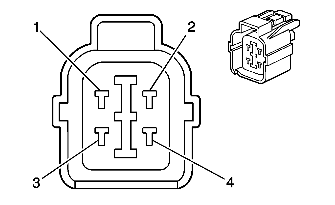
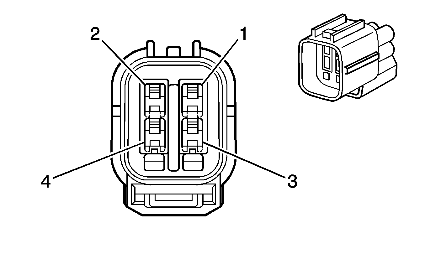
C120 Front Chassis Harness to Upfitter PTO Throttle Position Sensor Harness (PTO)
|
|
Connector Part Information
| Connector Part Information
|
Pin | Wire Color | Circuit No. | Function | Pin | Wire Color | Circuit No. | Function |
|---|---|---|---|---|---|---|---|
1 | L-BU/WH | DF22 | 5-Volt Reference | 1 | -- | -- | Upfitter Usage |
2 | L-BU/RD | DF23 | PTO Accel Switch Signal | 2 | -- | -- | Upfitter Usage |
3 | L-BU/YE | DF24 | Low Reference | 3 | -- | -- | Upfitter Usage |
4 | -- | -- | Not Used | 4 | -- | -- | Upfitter Usage |
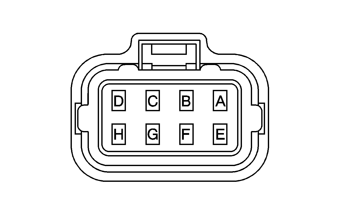
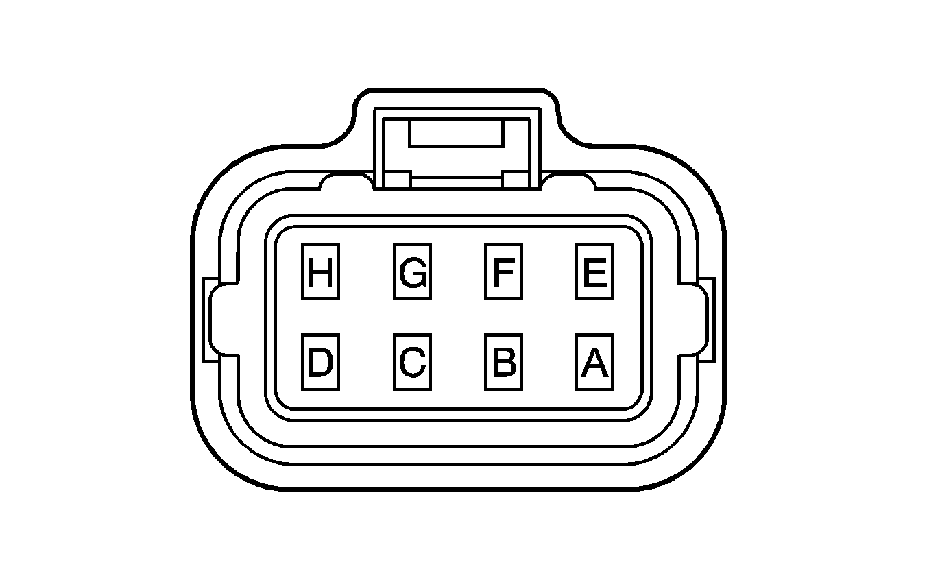
C122 Engine Harness to Fuel Injector Harness Connector Adapter 1 to Injector Harness 1
|
|
Connector Part Information
| Connector Part Information
|
Pin | Wire Color | Circuit No. | Function | Pin | Wire Color | Circuit No. | Function |
|---|---|---|---|---|---|---|---|
A | WH | B5 | Fuel Injector Supply Voltage 1 | A | WH | 7 | Fuel Injector Supply Voltage 1 |
B | WH | B3 | Fuel Injector Supply Voltage 1 | B | WH | 4 | Fuel Injector Supply Voltage 1 |
C | YE | B58 | Fuel Injector 1 Control | C | D-GN | 1 | Fuel Injector 1 Control |
D-E | -- | -- | Not Used | D-E | -- | -- | Not Used |
F | D-BU | B57 | Fuel Injector 2 Control | F | D-BU | 2 | Fuel Injector 2 Control |
G | WH | B56 | Fuel Injector 3 Control | G | YE | 3 | Fuel Injector 3 Control |
H | -- | -- | Not Used | H | -- | -- | Not Used |
C123 Engine Harness to Fuel Injector Harness Connector Adapter 2 to Injector Harness 2

|

|
Connector Part Information
| Connector Part Information
|
Pin | Wire Color | Circuit No. | Function | Pin | Wire Color | Circuit No. | Function |
|---|---|---|---|---|---|---|---|
A | RD | B6 | Fuel Injector Supply Voltage 2 | A | RD | 7 | Fuel Injector Supply Voltage 2 |
B | RD | B4 | Fuel Injector Supply Voltage 2 | B | RD | 4 | Fuel Injector Supply Voltage 2 |
C | BK | B44 | Fuel Injector 4 Control | C | BK | 1 | Fuel Injector 4 Control |
D-E | -- | -- | Not Used | D-E | -- | -- | Not Used |
F | BK/RD | B45 | Fuel Injector 5 Control | F | BN | 2 | Fuel Injector 5 Control |
G | RD | B43 | Fuel Injector 6 Control | G | VT | 3 | Fuel Injector 6 Control |
H | -- | -- | Not Used | H | -- | -- | Not Used |
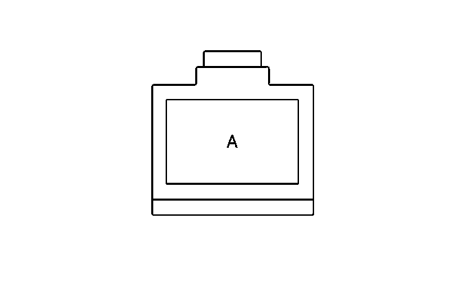
C125 Engine Chassis Harness to Front Chassis Harness
|
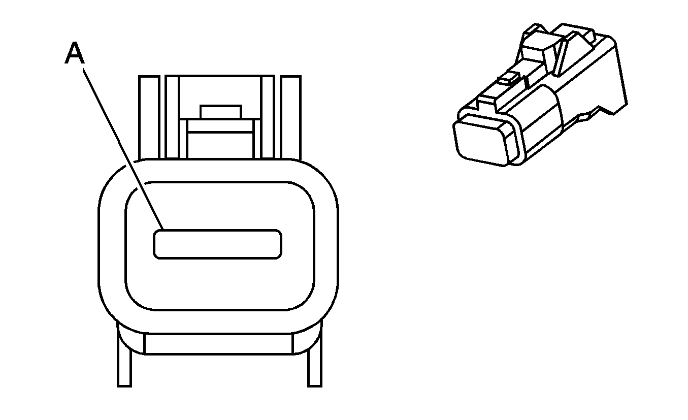
|
Connector Part Information
| Connector Part Information
|
Pin | Wire Color | Circuit No. | Function | Pin | Wire Color | Circuit No. | Function |
|---|---|---|---|---|---|---|---|
A | WH | PA27 | Crank Signal | A | BK/WH | PA27 | Crank Signal |
C200 Lower I/P Harness to Front Chassis Harness
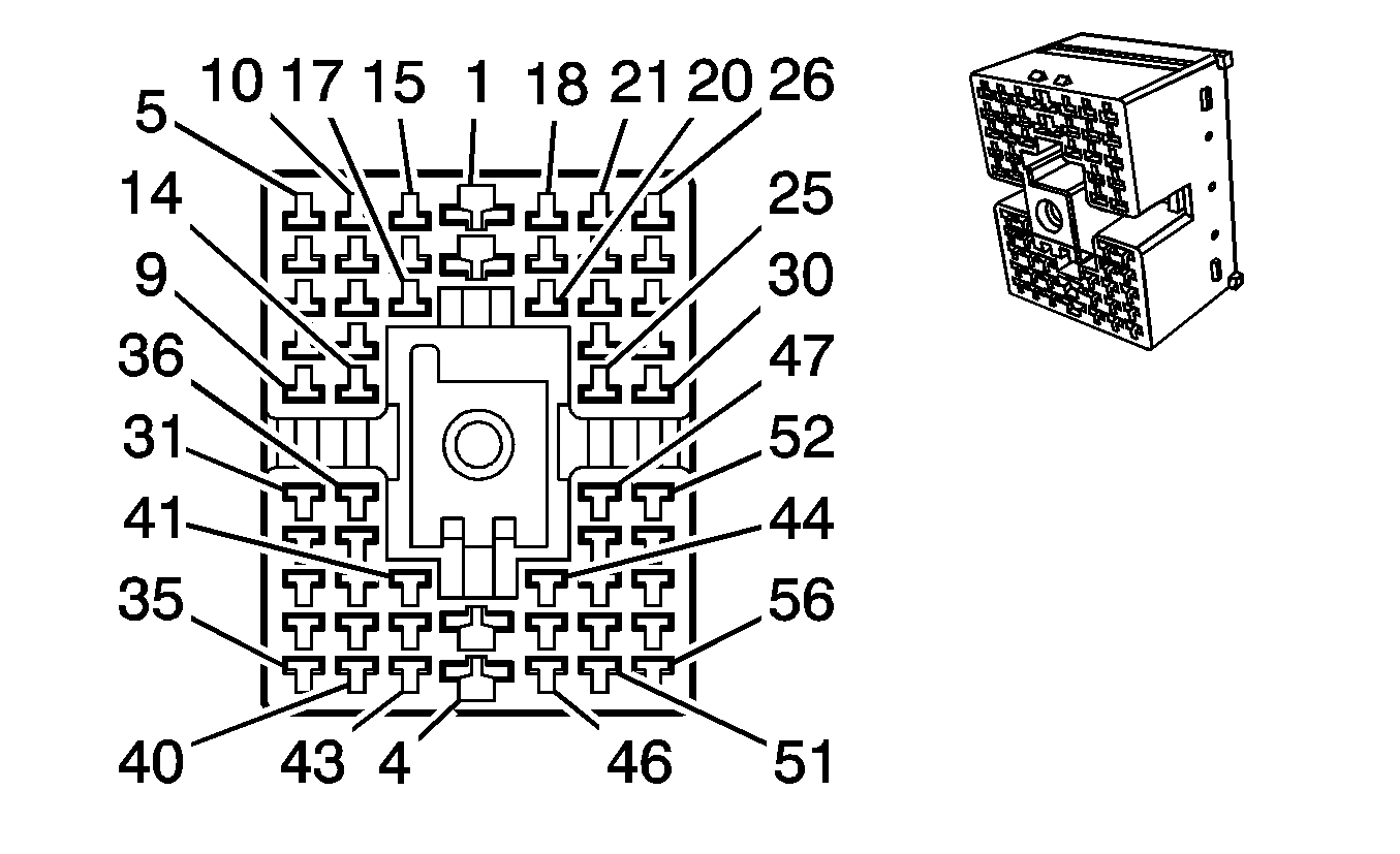
|
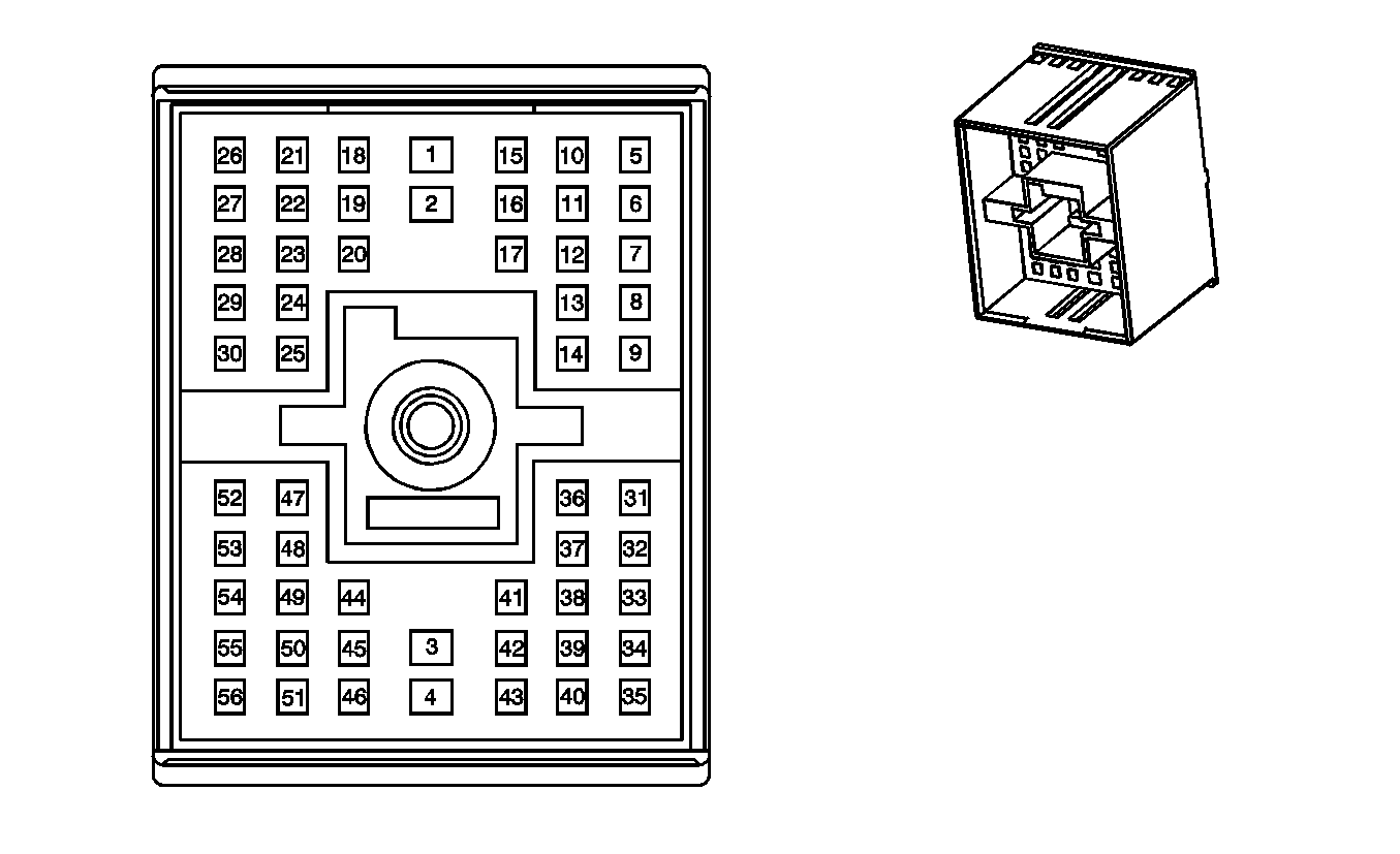
|
Connector Part Information
| Connector Part Information
|
Pin | Wire Color | Circuit No. | Function | Pin | Wire Color | Circuit No. | Function |
|---|---|---|---|---|---|---|---|
1 | YE/RD | PA09 | Battery Positive Voltage | 1 | YE/RD | PA09 | Battery Positive Voltage |
2 | YE/D-GN | PA10 | Battery Positive Voltage | 2 | YE/D-GN | PA10 | Battery Positive Voltage |
3 | BK | ZZ11 | Ground | 3 | BK | PX02 | Ground |
4 | BK | ZZ12 | Ground | 4 | BK | AX05 | Ground |
5 | BN/WH | PA20 | Ignition 1 Voltage | 5 | BN/WH | PA20 | Ignition 1 Voltage |
6-7 | -- | -- | Not Used | 6-7 | -- | -- | Not Used |
8 | D-BU | BG02 | Secondary Brake Warning Indicator Control (JE3) | 8 | D-BU | BG02 | Secondary Brake Warning Indicator Control (JE3) |
WH | BB07 | Secondary Brake Warning Indicator Control (JE4) | WH/BK | BB07 | Secondary Brake Warning Indicator Control (JE4) | ||
9 | BN | PA29 | Charge Indicator Control | 9 | RD | PA29 | Charge Indicator Control |
10 | BK/WH | HU03 | Ground | 10 | BK/WH | HU03 | Ground |
11 | BN/RD | BB10 | Traction Active Indicator Control | 11 | BN | BG08 | Traction Active Indicator Control (JE3) |
BN | BB10 | Traction Active Indicator Control (JE4) | |||||
12 | L-BU | BB11 | Traction Control Switch Signal | 12 | L-BU | BG09 | Traction Control Switch Signal (JE3) |
L-BU | BB11 | Traction Control Switch Signal (JE4) | |||||
13 | BN/WH | MA09 | Low Air Pressure Switch Signal (JE4) | 13 | BN | MA09 | Low Air Pressure Switch Signal (JE4) |
-- | -- | Not Used (JE3) | -- | -- | Not Used (JE3) | ||
14 | VT | WB05 | PTO Control | 14 | VT | WB05 | PTO Control |
15 | WH/D-BU | BB16 | J1708 Serial Data A (JE4) | 15 | -- | -- | Not Used (JE3) |
WH/D-BU | BB16 | J1708 Serial Data A (JE4) | |||||
16 | D-GN | BB17 | J1708 Serial Data B (JE4) | 16 | -- | -- | Not Used (JE3) |
BK/D-BU | BB17 | J1708 Serial Data B (JE4) | |||||
17 | -- | -- | Not Used | 17 | -- | -- | Not Used |
18 | D-GN | DA02 | Horn Control | 18 | D-GN/WH | DA02 | Horn Control |
19 | YE | JA20 | Left Rear Stop/Turn Lamp Supply Voltage | 19 | YE | JA20 | Left Rear Stop/Turn Lamp Supply Voltage |
20 | D-GN | JA21 | Right Rear Stop/Turn Lamp Supply Voltage | 20 | D-GN | JA21 | Right Rear Stop/Turn Lamp Supply Voltage |
21 | BN | BA09 | Park Lamp Supply Voltage | 21 | BN | BA09 | Park Lamp Supply Voltage |
22 | PK | BB01 | Ignition 1 Voltage | 22 | PK | BG30 | Ignition 1 Voltage (JE3) |
PK | BB01 | Ignition 1 Voltage (JE4) | |||||
23 | BK/WH | BB15 | ABS Active Signal | 23 | BK | BG19 | ABS Active Signal (JE3) |
BK/WH | BB15 | ABS Active Signal (JE4) | |||||
24 | L-GN | SB02 | Engine Brake Enable Signal | 24 | WH/D-GN | SB02 | Engine Brake Enable Signal |
25 | D-BU | CE02 | Air Suspension Dump Switch Signal | 25 | D-BU/RD | CE02 | Air Suspension Dump Switch Signal |
26 | L-GN | NB02 | Differential Lock Switch Signal | 26 | YE/BK | NB02 | Differential Lock Switch Signal |
27 | L-BU | HA06 | A/C Compressor Relay Supply Voltage | 27 | L-BU | HA06 | A/C Compressor Relay Supply Voltage |
28 | D-GN/WH | HA04 | Condenser Relay Control | 28 | D-GN/WH | HA04 | Condenser Relay Control |
29 | D-GN | HA25 | A/C Request Signal | 29 | D-GN/RD | HA25 | A/C Request Signal |
30 | D-BU/WH | HA02 | Condenser Fan Motor Supply Voltage | 30 | D-BU/WH | HA02 | Condenser Fan Motor Supply Voltage |
31 | WH | WB07 | PTO Relay Output | 31 | WH | WB07 | PTO Relay Output |
32-34 | -- | -- | Not Used | 32-34 | -- | -- | Not Used |
35 | D-BU | TF13 | CAN High | 35 | WH/RD | TF07 | CAN High |
36 | L-GN | WB09 | PTO On Switch - Signal | 36 | L-GN | WB09 | PTO On Switch - Signal |
37-38 | -- | -- | Not Used | 37-38 | -- | -- | Not Used |
39 | L-BU | DF45 | Stop Lamp Switch Signal | 39 | RD/D-BU | DF45 | Stop Lamp Switch Signal |
40 | BK/WH | TF14 | CAN High | 40 | L-GN/RD | TF08 | CAN High |
41-42 | -- | -- | Not Used | 41-42 | -- | -- | Not Used |
43 | GY/D-BU | TF15 | Shield | 43 | -- | -- | Not Used |
44 | D-GN | SA10 | Upfitter Pass-Through Circuit to Upfitter Connector C201, Pin C | 44 | D-GN | SA10 | Upfitter Pass-Through Circuit to Upfitter AUX WRG Connector C100, Pin D |
45 | GY | DF50 | Cruise Control On Switch Signal | 45 | RD/BK | DF50 | Cruise Control On Switch Signal |
46 | -- | -- | Not Used | 46 | -- | -- | Not Used |
47 | YE | HB04 | Glow Plug Relay Control | 47 | YE | HB04 | Glow Plug Relay Control |
48 | PU | DF44 | Engine Brake Enable Control | 48 | VT | DF44 | Engine Brake Enable Control |
49 | L-BU | DF47 | Cruise Control Set/Coast Switch Signal | 49 | L-BU | DF47 | Cruise Control Set/Coast Switch Signal |
50 | PK | DF55 | Ignition 2 Voltage | 50 | PK | DF55 | Ignition 2 Voltage |
51 | D-BU | SA11 | Upfitter Pass-Through Circuit to Front Chassis Harness Connector C100 (Upfitter AUX WRG Connector), Pin B | 51 | D-BU | SA11 | Upfitter Pass-Through Circuit to Lower I/P Harness Connector C201 (Upfitter Connector), Pin F |
52 | YE/BK | MA13 | Water In Fuel Indicator Control | 52 | YE/BK | MA13 | Water In Fuel Indicator Control |
53 | -- | -- | Not Used | 53 | -- | -- | Not Used |
54 | GY/BK | DF48 | Cruise Control Resume/Accel Switch Signal | 54 | RD | DF48 | Cruise Control Resume/Accel Switch Signal |
55 | D-BU/BK | DF72 | Fuel Heater Supply Voltage | 55 | D-BU/BK | DF72 | Fuel Heater Supply Voltage |
56 | -- | -- | Not Used | 56 | -- | -- | Not Used |
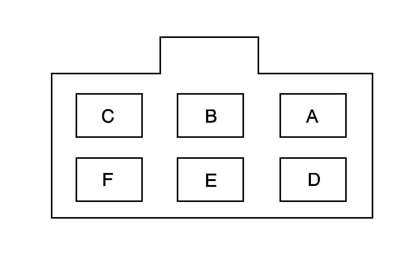
C201 Lower I/P Harness Upfitter Connector to Upfitter Harness
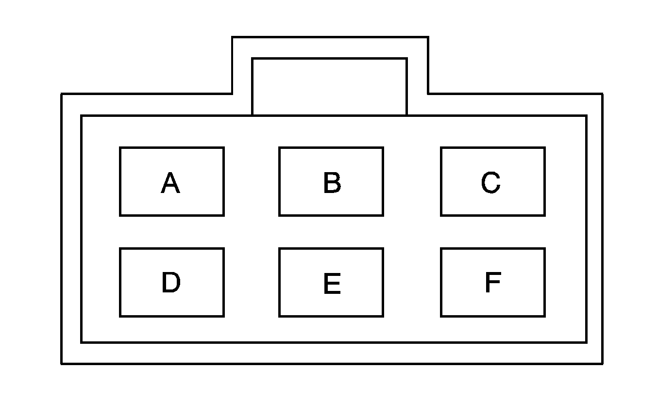
|
|
Connector Part Information
| Connector Part Information
|
Pin | Wire Color | Circuit No. | Function | Pin | Wire Color | Circuit No. | Function |
|---|---|---|---|---|---|---|---|
A | BN | SA12 | Interior Park Lamps Supply Voltage | A | -- | -- | Upfitter Usage |
B | OG | SA05 | Battery Positive Voltage | B | -- | -- | Upfitter Usage |
C | D-GN | SA10 | Upfitter Pass-Through Circuit to Front Chassis Harness Connector C100 (Upfitter AUX WRG Connector), Pin D | C | -- | -- | Upfitter Usage |
D | YE | SA13 | Ignition 2 Voltage | D | -- | -- | Upfitter Usage |
E | PK | SA09 | Ignition 1 Voltage | E | -- | -- | Upfitter Usage |
F | D-BU | SA11 | Upfitter Pass-Through Circuit to Front Chassis Harness Connector C100 (Upfitter AUX WRG Connector), Pin B | F | -- | -- | Upfitter Usage |
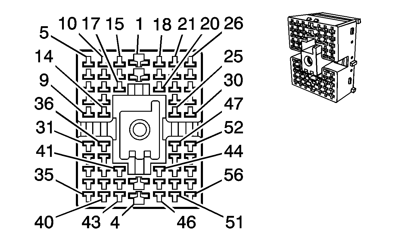
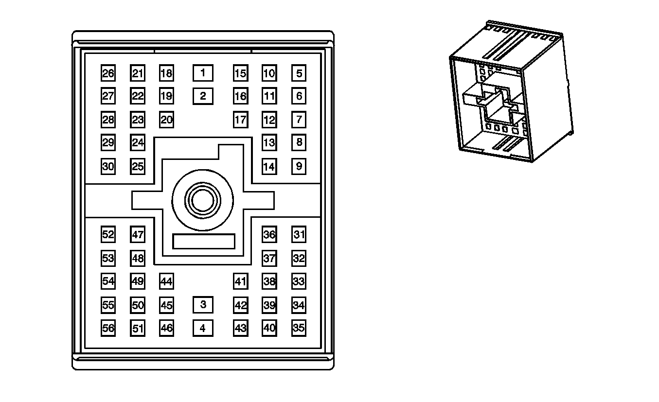
C202 Lower I/P Harness to Front Chassis Harness
|
|
Connector Part Information
| Connector Part Information
|
Pin | Wire Color | Circuit No. | Function | Pin | Wire Color | Circuit No. | Function |
|---|---|---|---|---|---|---|---|
1 | RD/YE | PA05 | Battery Positive Voltage | 1 | RD/YE | PA05 | Battery Positive Voltage |
2 | RD/D-BU | PA06 | Battery Positive Voltage | 2 | RD/D-BU | PA06 | Battery Positive Voltage |
3 | YE | PA07 | Battery Positive Voltage | 3 | YE | PA07 | Battery Positive Voltage |
4 | YE/BK | PA08 | Battery Positive Voltage | 4 | YE/BK | PA08 | Battery Positive Voltage |
5 | L-BU | BG04 | ABS/TCS Class 2 Serial Data (JE3) | 5 | L-BU/WH | BG04 | ABS/TCS Class 2 Serial Data (JE3) |
-- | -- | Not Used (JE4) | -- | -- | Not Used (JE4) | ||
6 | OG | CF08 | Battery Positive Voltage | 6 | L-BU/OG | CF08 | Battery Positive Voltage |
7 | D-BU | CF12 | APP Sensor 1 Signal | 7 | D-BU | CF12 | APP Sensor 1 Signal |
8 | L-BU | CF15 | APP Sensor 2 Signal | 8 | L-GN | CF15 | APP Sensor 2 Signal |
9 | WH | BB13 | Traction Active Indicator Control | 9 | WH | BG10 | Traction Active Indicator Control (JE3) |
WH | BB13 | Traction Active Indicator Control (JE4) | |||||
10 | RD/WH | CF04 | Ignition 1 Voltage | 10 | BK/RD | CF04 | Ignition 1 Voltage |
11 | PK | CF10 | Ignition 1 Voltage | 11 | PK | CF10 | Ignition 1 Voltage |
12 | TN | CF13 | Low Reference | 12 | TN | CF13 | Low Reference |
13 | PU | CF16 | Low Reference | 13 | VT | CF16 | Low Reference |
14 | YE/BK | CF17 | 5-Volt Reference | 14 | YE/BK | CF17 | 5-Volt Reference |
15 | WH | CF06 | ECM Power Enable Signal | 15 | WH | CF06 | ECM Power Enable Signal |
16 | WH/BK | CF11 | 5-Volt Reference | 16 | WH/BK | CF11 | 5-Volt Reference |
17 | BK/WH | CF14 | 5-Volt Reference | 17 | BK/WH | CF14 | 5-Volt Reference |
18 | WH | CF22 | Engine Speed Signal | 18 | WH | CF22 | Engine Speed Signal |
19 | RD | CF26 | High Idle Indicator Control | 19 | RD | CF26 | High Idle Indicator Control |
20 | D-GN | CF34 | Class 2 Serial Data | 20 | D-GN | CF34 | Class 2 Serial Data |
21 | D-GN/WH | CF23 | Vehicle Speed Signal | 21 | D-GN/WH | CF23 | Vehicle Speed Signal |
22 | BK/WH | CF29 | CPP Switch Signal | 22 | BK/OG | CF29 | CPP Switch Signal |
23 | -- | -- | Not Used | 23 | -- | -- | Not Used |
24 | BN | MF01 | Marker Lamp Supply Voltage (JE4, RQ2 and U86 or RQ3) | 24 | BK | MF01 | Marker Lamp Supply Voltage (JE4, RQ2 and U86 or RQ3) |
-- | -- | Not Used (JE3) | -- | -- | Not Used (JE3) | ||
25 | RD/BK | DF02 | PTO Disable Switch Signal - Cab | 25 | RD/BK | DF02 | PTO Disable Switch Signal - Cab |
26 | D-GN | CF24 | High Idle Switch Signal | 26 | D-GN | CF24 | High Idle Switch Signal |
27 | WH | CF32 | Engine Brake Enable Signal | 27 | WH | CF32 | Engine Brake Enable Signal |
28 | -- | -- | Not Used | 28 | -- | -- | Not Used |
29 | WH/BK | DF01 | Brake/Clutch Switch Override Signal | 29 | WH/BK | DF01 | Brake/Clutch Switch Override Signal |
30 | D-GN/WH | DF03 | PTO Disable Switch Signal B - Cab | 30 | D-GN/WH | DF03 | PTO Disable Switch Signal B - Cab |
31 | PK | FC01 | Ignition 1 Voltage | 31 | PK | FC01 | Ignition 1 Voltage |
32 | GY/BK | FC02 | Two Speed Rear Axle Shift Motor Relay Control | 32 | RD/D-BU | FC02 | Two Speed Rear Axle Shift Motor Relay Control |
33 | D-GN | CF18 | APP Sensor 3 Signal | 33 | D-GN | CF18 | APP Sensor 3 Signal |
34 | BN/WH | CF20 | MIL Control | 34 | BK/WH | CF20 | MIL Control |
35 | D-BU | CF21 | Wait to Start Indicator Control | 35 | D-BU | CF21 | Wait to Start Indicator Control |
36 | D-BU | SA19 | Rear Compartment Lamp Supply Voltage | 36 | D-BU/WH | SA19 | Rear Compartment Lamp Supply Voltage |
37 | OG | SA04 | Battery Positive Voltage | 37 | RD | SA04 | Battery Positive Voltage |
38 | RD | CF19 | Low Reference | 38 | RD | CF19 | Low Reference |
39 | PK | SA07 | Ignition 1 Voltage | 39 | PK/D-BU | SA07 | Ignition 1 Voltage |
40 | L-BU | JA12 | Left Turn Signal Lamp Supply Voltage | 40 | L-BU | JA12 | Left Turn Signal Lamp Supply Voltage |
41 | WH | DF46 | Stop Lamp Switch Signal | 41 | WH | BG18 | Stop Lamp Switch Signal (JE3) |
WH | DF46 | Stop Lamp Switch Signal (JE4) | |||||
42 | -- | -- | Not Used | 42 | -- | -- | Not Used |
43 | D-BU | JA16 | Right Turn Signal Lamp Supply Voltage | 43 | D-BU | JA16 | Right Turn Signal Lamp Supply Voltage |
44 | YE | JA03 | Left Rear Trailer Stop/Turn Lamp Supply Voltage | 44 | YE | JA03 | Left Rear Trailer Stop/Turn Lamp Supply Voltage |
45 | D-GN | JA06 | Right Rear Trailer Stop/Turn Lamp Supply Voltage | 45 | D-GN | JA06 | Right Rear Trailer Stop/Turn Lamp Supply Voltage |
46 | YE | PA13 | PNP/Clutch Start Switch Signal | 46 | YE | PA13 | PNP/Clutch Start Switch Signal |
-- | -- | Not Used (Allison® LCT) | -- | -- | Not Used (Allison® LCT) | ||
47 | BK/WH | DF04 | PTO Set Switch Signal A - Cab | 47 | BK/WH | DF04 | PTO Set Switch Signal A - Cab |
48 | -- | -- | Not Used | 48 | YE/BK | DF11 | Ground |
-- | -- | Not Used (Allison® LCT) | -- | -- | Not Used (Allison® LCT) | ||
49 | -- | -- | Not Used | 49 | -- | -- | Not Used |
50 | YE | OA55 | Crank Voltage | 50 | YE/D-GN | OA55 | Crank Voltage |
51 | BK/WH | MX02 | Ground | 51 | BK/WH | MX02 | Ground |
52-54 | -- | -- | Not Used | 52-54 | -- | -- | Not Used |
55 | YE/D-BU | NF58 | PNP/Clutch Start Switch Signal | 55 | YE | NF58 | PNP/Clutch Start Switch Signal (M/T) |
-- | -- | Not Used (A/T) | |||||
56 | BK/WH | HU01 | Ground | 56 | BK/WH | HU01 | Ground |
C203 Lower I/P Harness (JE4 - TRUCK Connector) to Lower I/P Harness (Connected for Truck Service, Not Connected for Tractor Service)

|

|
Connector Part Information
| Connector Part Information
|
Pin | Wire Color | Circuit No. | Function | Pin | Wire Color | Circuit No. | Function |
|---|---|---|---|---|---|---|---|
A | BN | BA13 | Tail Lamp Supply Voltage | A | BN | BA14 | Tail Lamp Supply Voltage |
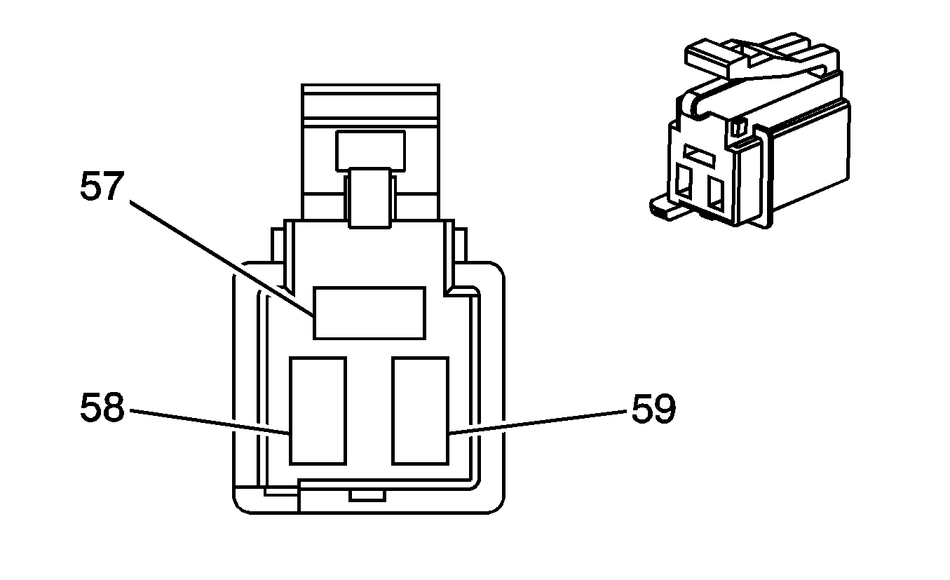
C204 Front Chassis Harness to Lower I/P Harness
|
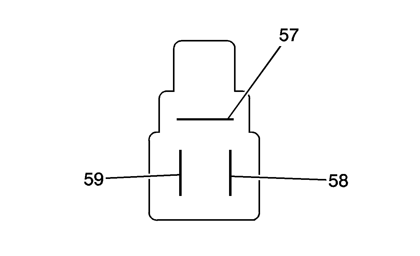
|
Connector Part Information
| Connector Part Information
|
Pin | Wire Color | Circuit No. | Function | Pin | Wire Color | Circuit No. | Function |
|---|---|---|---|---|---|---|---|
57 | RD/D-GN | PA04 | Battery Positive Voltage | 57 | RD/D-GN | PA04 | Battery Positive Voltage |
58 | RD/WH | PA03 | Battery Positive Voltage | 58 | RD/WH | PA03 | Battery Positive Voltage |
59 | RD/BK | PA02 | Battery Positive Voltage | 59 | RD/BK | PA02 | Battery Positive Voltage |
C205 Front Chassis Harness to Lower I/P Harness

|

|
Connector Part Information
| Connector Part Information
|
Pin | Wire Color | Circuit No. | Function | Pin | Wire Color | Circuit No. | Function |
|---|---|---|---|---|---|---|---|
A | RD | HB01 | Battery Positive Voltage | A | RD | HB01 | Battery Positive Voltage |
C207 Front Chassis Harness to Lower I/P Harness

|

|
Connector Part Information
| Connector Part Information
|
Pin | Wire Color | Circuit No. | Function | Pin | Wire Color | Circuit No. | Function |
|---|---|---|---|---|---|---|---|
A | RD/BK | HB02 | Battery Positive Voltage | A | RD/BK | HB02 | Battery Positive Voltage |
C208 Lower I/P Harness to Roof Harness
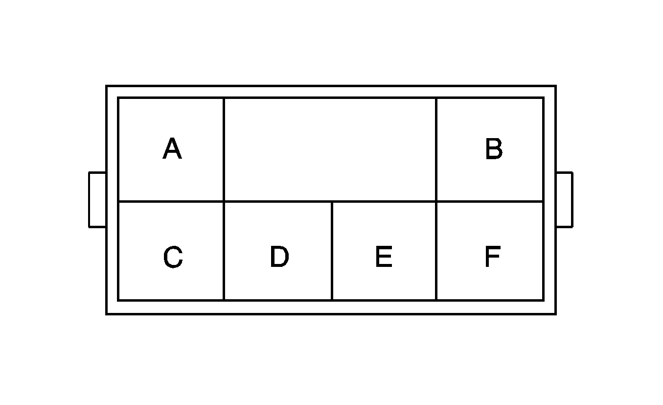
|
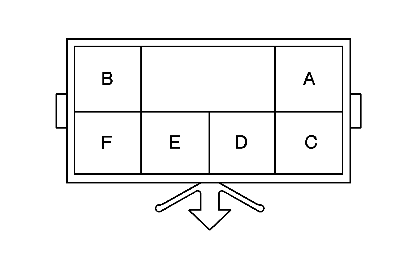
|
Connector Part Information
| Connector Part Information
|
Pin | Wire Color | Circuit No. | Function | Pin | Wire Color | Circuit No. | Function |
|---|---|---|---|---|---|---|---|
A | -- | -- | Not Used | A | RD | 3 | Courtesy Lamps On Signal (SEO) |
B | RD/YE | IA02 | Dome Lamp/Side Door Jamb Switch Signal | B | RD/YE | 2 | Dome Lamp/Side Door Jamb Switch Signal |
C | BN | BA12 | Roof Lamps Supply Voltage (RQ2) | C | BN | 5 | Roof Lamps Supply Voltage |
BA20 | Roof Lamps Supply Voltage (RQ2 & U86 or RQ3) | ||||||
D | -- | -- | Not Used | D | -- | -- | Not Used |
E | BK | ZZ07 | Ground | E | BK | 4 | Ground |
F | OG | IA01 | Battery Positive Voltage | F | OG | 1 | Battery Positive Voltage |
C209 Lower I/P Harness to Upfitter New Feature Switch Harness

|

|
Connector Part Information
| Connector Part Information
|
Pin | Wire Color | Circuit No. | Function | Pin | Wire Color | Circuit No. | Function |
|---|---|---|---|---|---|---|---|
A | WH/BK | DF01 | Brake/Clutch Switch Override Signal | A | -- | -- | Upfitter Usage |
B | RD/BK | DF02 | PTO Disable Switch Signal - Cab | B | -- | -- | Upfitter Usage |
C | D-GN/WH | DF03 | PTO Disable Switch Signal B - Cab | C | -- | -- | Upfitter Usage |
D | BK/WH | DF04 | PTO Set Switch Signal A - Cab | D | -- | -- | Upfitter Usage |
E | BK | CU04 | Ground | E | -- | -- | Upfitter Usage |
F | -- | -- | Not Used | F | -- | -- | Upfitter Usage |
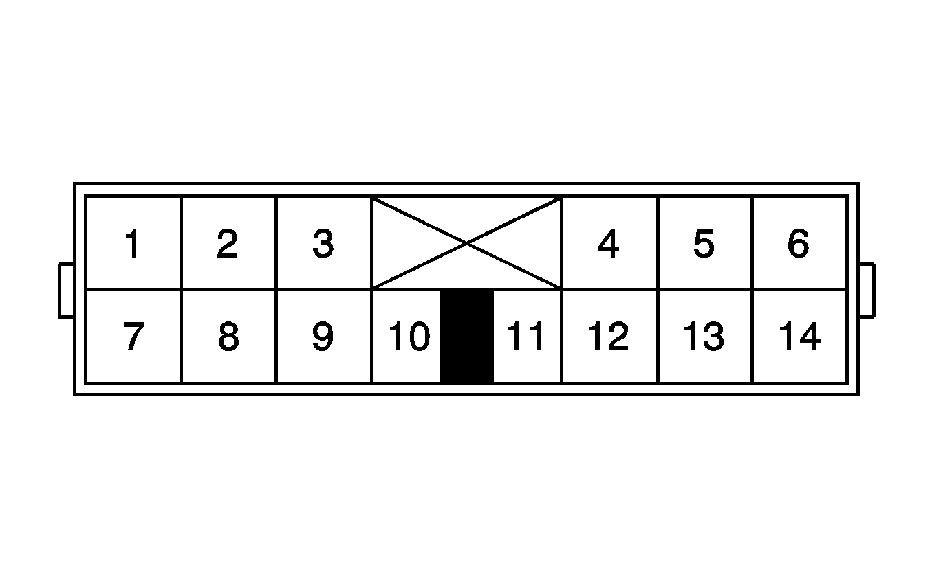
C210 Floor Harness to Lower I/P Harness
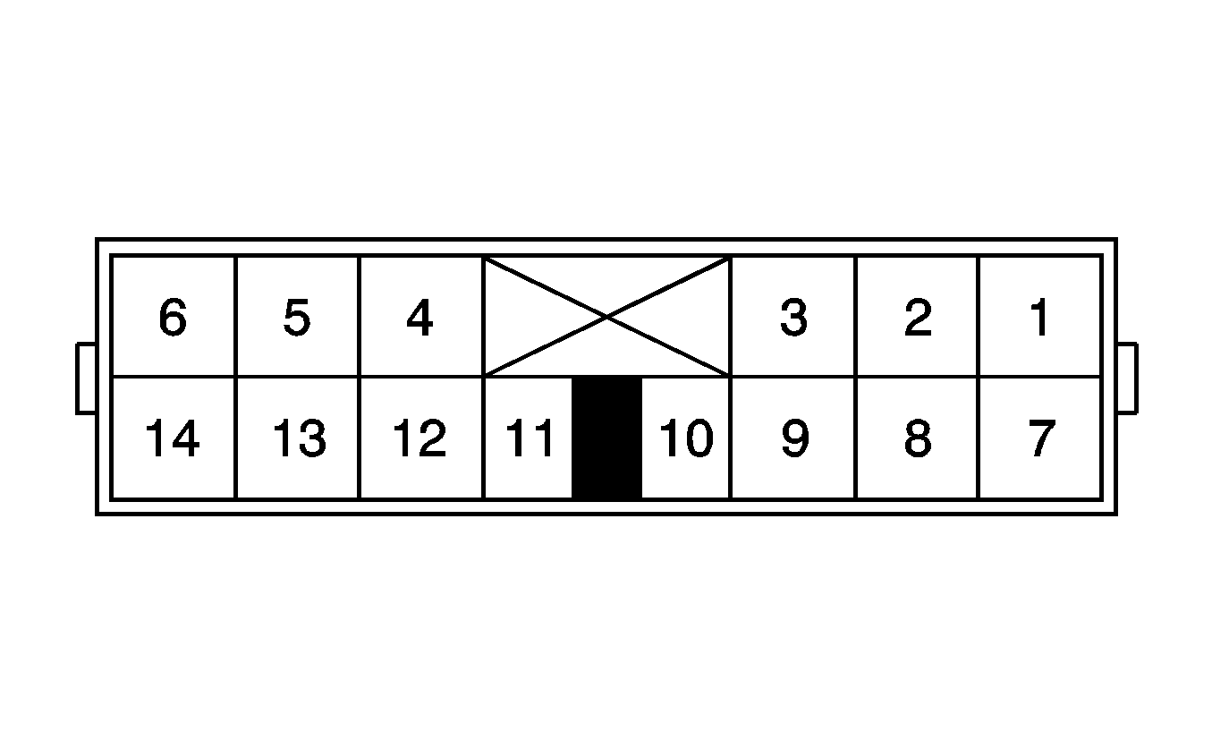
|
|
Connector Part Information
| Connector Part Information
|
Pin | Wire Color | Circuit No. | Function | Pin | Wire Color | Circuit No. | Function |
|---|---|---|---|---|---|---|---|
1 | GY/BK | FC02 | Shift - Signal | 1 | GY/BK | FC02 | Shift - Signal |
2 | BK | SX03 | Ground | 2 | BK | SX03 | Ground |
3 | D-GN/RD | SA03 | Battery Positive Voltage | 3 | D-GN/RD | SA03 | Battery Positive Voltage |
4 | WH | MF10 | Trailer Stop Lamp Switch Signal (RQ2 & U86 or RQ3) | 4 | WH | MF10 | Trailer Stop Lamp Switch Signal (RQ2 & U86 or RQ3) |
-- | -- | Not Used (w/o RQ2 & U86 or RQ3) | -- | -- | Not Used (w/o RQ2 & U86 or RQ3) | ||
5 | OG | MF09 | Battery Positive Voltage (RQ2 & U86 or RQ3) | 5 | OG | MF09 | Battery Positive Voltage (RQ2 & U86 or RQ3) |
-- | -- | Not Used (w/o RQ2 & U86 or RQ3) | -- | -- | Not Used (w/o RQ2 & U86 or RQ3) | ||
6 | D-BU/BK | BF05 | Park Brake Switch Signal | 6 | D-BU/BK | BF05 | Park Brake Switch Signal |
7-9 | -- | -- | Not Used | 7-9 | -- | -- | Not Used |
10 | BK/RD | OA14 | Instrument Panel Lamps Dimming Supply Voltage | 10 | BK/RD | OA14 | Instrument Panel Lamps Dimming Supply Voltage |
11 | D-BU | CE02 | Air Suspension Dump Switch Signal | 11 | D-BU | CE02 | Air Suspension Dump Switch Signal |
12 | L-GN | NB02 | Differential Lock Switch Signal | 12 | L-GN | NB02 | Differential Lock Switch Signal |
13 | PK | NB01 | Ignition 1 Voltage | 13 | PK | NB01 | Ignition 1 Voltage |
14 | RD/BK | IA03 | Side Door Jamb Switch Signal | 14 | RD/BK | IA03 | Side Door Jamb Switch Signal |
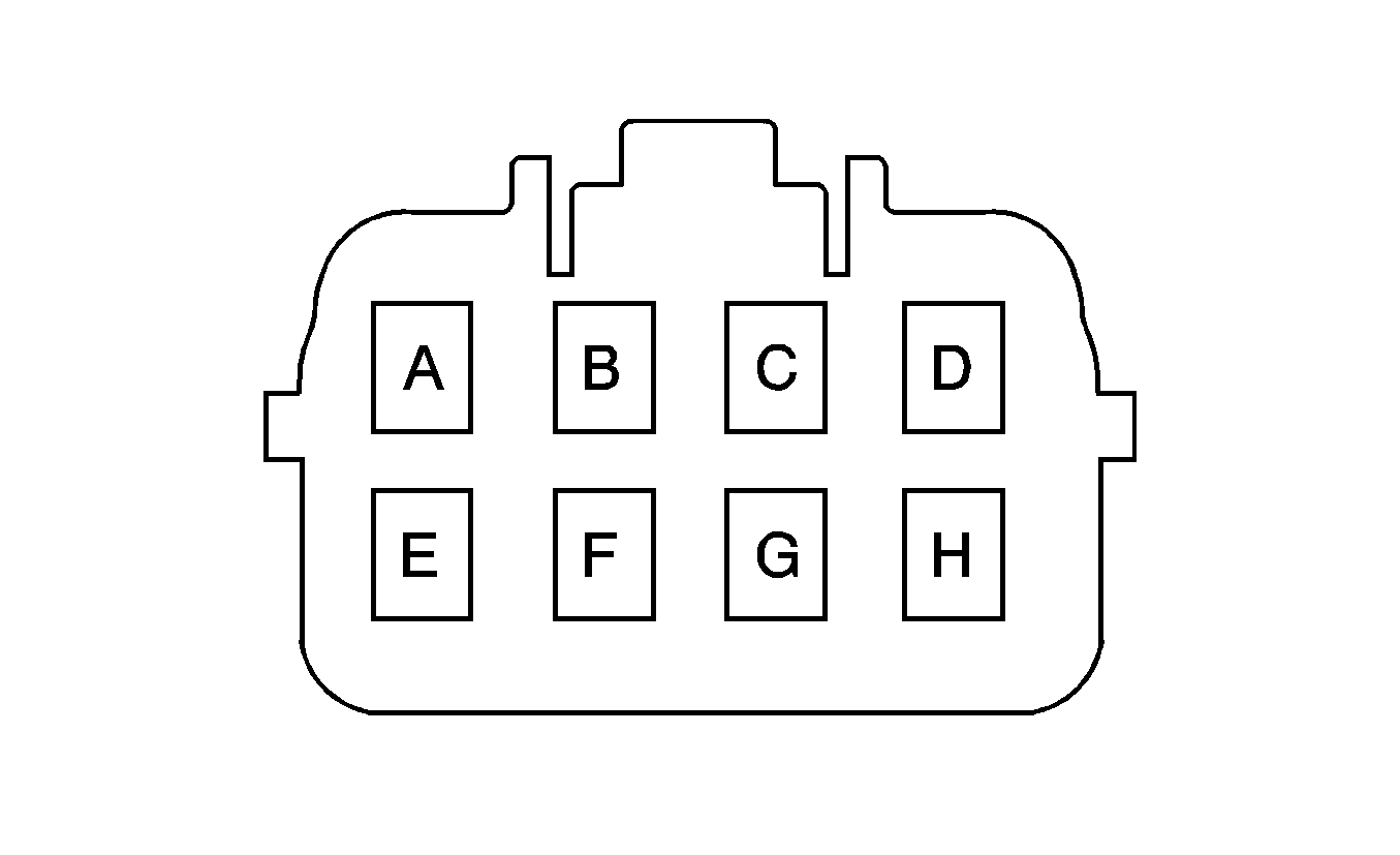
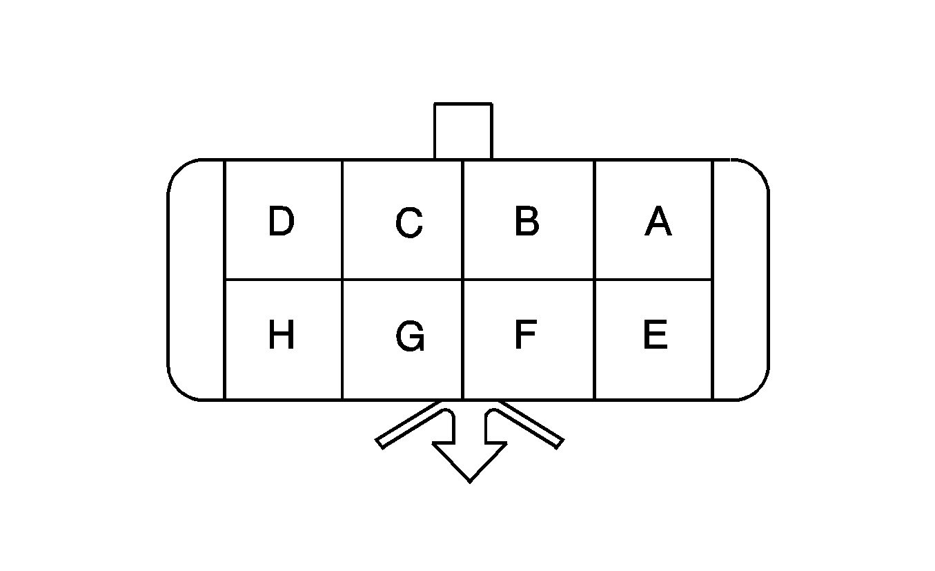
C211 Lower I/P Harness to Dash Harness
|
|
Connector Part Information
| Connector Part Information
|
Pin | Wire Color | Circuit No. | Function | Pin | Wire Color | Circuit No. | Function |
|---|---|---|---|---|---|---|---|
A | BN/WH | FA06 | Battery Positive Voltage | A | D-BU/RD | 6 | Battery Positive Voltage |
B | D-BU/OG | FA07 | Washer Pump Switch Control | B | D-BU/OG | 7 | Washer Pump Switch Control |
C-D | -- | -- | Not Used | C-D | -- | -- | Not Used |
E | L-GN | HA19 | Evaporator Temperature Reference Voltage | E | L-GN | 16 | Evaporator Temperature Reference Voltage |
F | D-GN/YE | HA21 | Evaporator Temperature Low Reference | F | D-GN/YE | 17 | Evaporator Temperature Low Reference |
G | D-GN/RD | HA20 | Evaporator Temperature Sensor Signal | G | D-GN/RD | 18 | Evaporator Temperature Sensor Signal |
H | -- | -- | Not Used | H | -- | -- | Not Used |
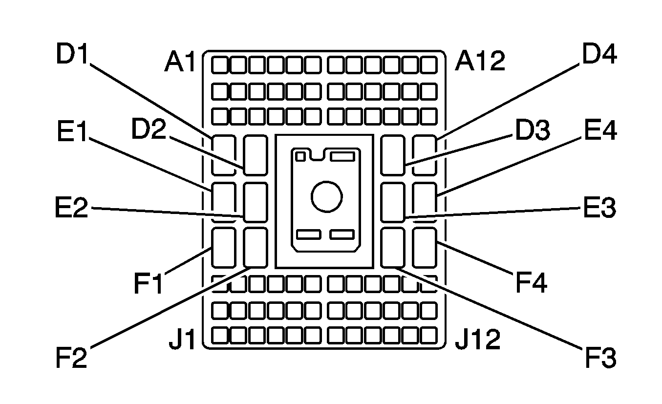
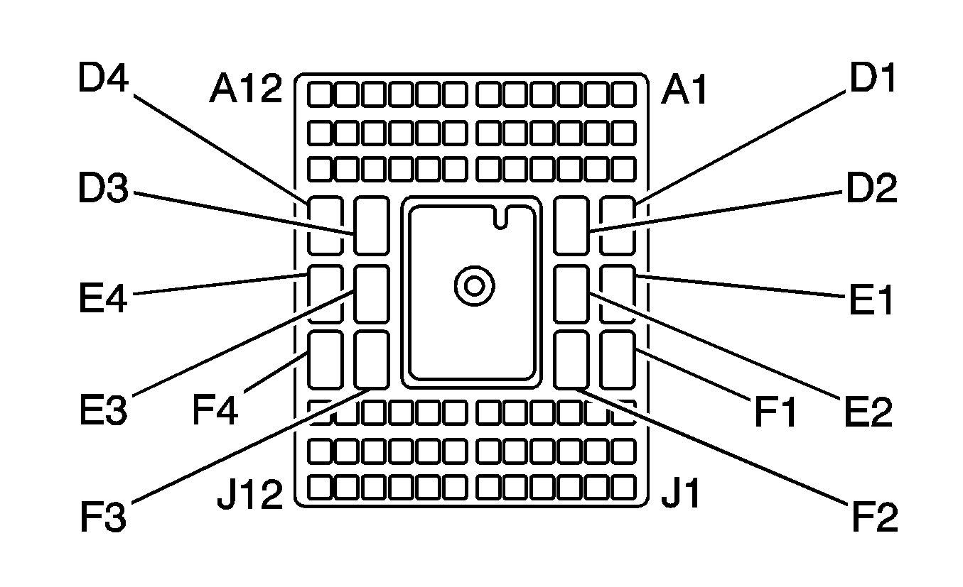
C212 Lower I/P Harness to Upper I/P Harness
|
|
Connector Part Information
| Connector Part Information
|
Pin | Wire Color | Circuit No. | Function | Pin | Wire Color | Circuit No. | Function |
|---|---|---|---|---|---|---|---|
A1 | YE | MA01 | Ignition 2 Voltage | A1 | YE | MA01 | Ignition 2 Voltage |
A2 | -- | -- | Not Used | A2 | -- | -- | Not Used |
A3 | PK | MA03 | Ignition 2 Voltage | A3 | PK | MA03 | Ignition 2 Voltage |
A4-A5 | -- | -- | Not Used | A4-A5 | -- | -- | Not Used |
A6 | BN/WH | CF20 | MIL Control | A6 | BN/WH | CF20 | MIL Control |
A7 | BN/YE | HA31 | Mode Door Position Signal D | A7 | BN/YE | HA31 | Mode Door Position Signal D |
A8 | BN/D-GN | HA30 | Mode Door Position Signal C | A8 | BN/D-GN | HA30 | Mode Door Position Signal C |
A9 | BN | HA28 | Mode Door Position Signal A | A9 | BN | HA28 | Mode Door Position Signal A |
A10 | BN/WH | HA29 | Mode Door Position Signal B | A10 | BN/WH | HA29 | Mode Door Position Signal B |
A11 | L-GN/ BK | HA34 | Mode Door Control B | A11 | L-GN/ BK | HA34 | Mode Door Control B |
A12 | L-GN | HA27 | Mode Door Control A | A12 | L-GN | HA27 | Mode Door Control A |
B1 | BK/WH | MX02 | Ground | B1 | BK/WH | MX02 | Ground |
B2-B3 | -- | -- | Not Used | B2-B3 | -- | -- | Not Used |
B4 | WH | CF22 | Engine Speed Signal | B4 | WH | CF22 | Engine Speed Signal |
B5 | BK | MX07 | Ground | B5 | BK | MX07 | Ground |
B6 | PU/WH | HA42 | Recirculation Door Position Signal | B6 | PU/WH | HA42 | Recirculation Door Position Signal |
B7 | BN/D-BU | HA32 | Mode Door Position Signal E | B7 | BN/D-BU | HA32 | Mode Door Position Signal E |
B8 | BN/BK | HA33 | Mode Door Position Signal F | B8 | BN/BK | HA33 | Mode Door Position Signal F |
B9 | L-GN/ WH | HA35 | Air Temperature Door Control A | B9 | L-GN/ WH | HA35 | Air Temperature Door Control A |
B10 | L-GN | HA39 | Air Temperature Door Control B | B10 | L-GN | HA39 | Air Temperature Door Control B |
B11 | PK | HA36 | 5-Volt Reference | B11 | PK | HA36 | 5-Volt Reference |
B12 | PK/D-BU | HA37 | Low Reference | B12 | PK/D-BU | HA37 | Low Reference |
C1 | GY/BK | FC03 | Shift - Signal | C1 | GY/BK | FC03 | Shift - Signal |
C2 | GY | MA04 | Class 2 Serial Data | C2 | GY | MA04 | Class 2 Serial Data |
C3 | L-BU | JA13 | Park/Turn Signal Lamp - LF Control | C3 | L-BU | JA13 | Park/Turn Signal Lamp - LF Control |
C4 | D-BU | JA17 | Park/Turn Signal Lamp - RF Control | C4 | D-BU | JA17 | Park/Turn Signal Lamp - RF Control |
C5 | BN/WH | MA12 | Ignition 1 Voltage | C5 | BN/WH | MA12 | Ignition 1 Voltage |
C6 | RD/YE | AA26 | High Beam Signal | C6 | RD/YE | AA26 | High Beam Signal |
C7 | PK/BK | HA38 | Air Temperature Door Position Signal | C7 | PK/BK | HA38 | Air Temperature Door Position Signal |
C8 | PU/YE | HA40 | Recirculation Door Control A | C8 | PU/YE | HA40 | Recirculation Door Control A |
C9 | PU/D-GN | HA41 | Recirculation Door Control B | C9 | PU/D-GN | HA41 | Recirculation Door Control B |
C10 | D-BU/YE | HA14 | Medium 2 Blower Motor Control | C10 | D-BU/YE | HA14 | Medium 2 Blower Motor Control |
C11 | D-BU/BK | HA15 | Medium 1 Blower Motor Control | C11 | D-BU/BK | HA15 | Medium 1 Blower Motor Control |
C12 | D-BU/WH | HA16 | Low Blower Motor Control | C12 | D-BU/WH | HA16 | Low Blower Motor Control |
D1 | -- | -- | Not Used | D1 | -- | -- | Not Used |
D2 | OG | BA16 | Marker Lamp Supply Voltage | D2 | OG | BA16 | Marker Lamp Supply Voltage |
D3 | L-GN | HA17 | Blower Motor Supply Voltage | D3 | L-GN | HA17 | Blower Motor Supply Voltage |
D4 | D-BU/RD | HA12 | High Blower Motor Control | D4 | D-BU/RD | HA12 | High Blower Motor Control |
E1 | BN | MA05 | Ignition 1 Voltage | E1 | BN | MA05 | Ignition 1 Voltage |
E2 | OG | WA02 | Mirror Heating Element Supply Voltage | E2 | OG | WA02 | Mirror Heating Element Supply Voltage |
E3 | D-GN | HA22 | A/C Request Signal | E3 | D-GN | HA22 | A/C Request Signal |
E4 | PK | CF25 | Ignition 1 Voltage | E4 | PK | CF25 | Ignition 1 Voltage |
F1 | PK | WA01 | Ignition 1 Voltage | F1 | PK | WA01 | Ignition 1 Voltage |
F2 | BN/WH | MA07 | Ignition 1 Voltage | F2 | BN/WH | MA07 | Ignition 1 Voltage |
F3 | OG | MA02 | Battery Positive Voltage | F3 | OG | MA02 | Battery Positive Voltage |
F4 | BK | ZZ06 | Ground | F4 | BK | ZZ06 | Ground |
G1 | GY | DF49 | Cruise Control On Switch Signal | G1 | GY | DF49 | Cruise Control On Switch Signal |
G2 | L-GN | SB03 | Engine Brake Enable Signal | G2 | L-GN | SB03 | Engine Brake Enable Signal |
G3 | -- | -- | Not Used | G3 | -- | -- | Not Used |
G4 | WH | CF32 | Engine Brake Enable Signal | G4 | WH | CF32 | Engine Brake Enable Signal |
G5 | -- | -- | Not Used | G5 | -- | -- | Not Used |
G6 | D-GN/WH | RA07 | Right Speaker Output (-) | G6 | D-GN/WH | RA07 | Right Speaker Output (-) |
G7 | BN/RD | BB09 | Secondary Brake Warning Indicator Control | G7 | BN/RD | BB09 | Secondary Brake Warning Indicator Control |
G8 | L-BU | BB11 | Traction Control Switch Signal | G8 | L-BU | BB11 | Traction Control Switch Signal |
G9 | WH | BB13 | Traction Active Indicator Control | G9 | WH | BB13 | Traction Active Indicator Control |
G10 | D-BU/OG | BF03 | Park Brake Switch Signal (JE4) | G10 | D-BU/OG | BF03 | Park Brake Switch Signal |
D-BU/OG | BF04 | Park Brake Switch Signal (JE3) | |||||
G11 | L-GN | WB02 | PTO On Switch - Signal | G11 | L-GN | WB02 | PTO On Switch - Signal |
G12 | BN/WH | MA09 | Low Air Pressure Switch Signal | G12 | BN/WH | MA09 | Low Air Pressure Switch Signal |
H1-H2 | -- | -- | Not Used | H1-H2 | -- | -- | Not Used |
H3 | D-GN/WH | CF23 | Vehicle Speed Signal | H3 | D-GN/WH | CF23 | Vehicle Speed Signal |
H4 | D-BU | SA15 | Rear Compartment Lamp Switch Signal | H4 | D-BU | SA15 | Rear Compartment Lamp Switch Signal |
H5 | D-BU/WH | RA05 | Left Speaker Output (-) | H5 | D-BU/WH | RA05 | Left Speaker Output (-) |
H6 | D-GN | RA08 | Right Speaker Output (+) | H6 | D-GN | RA08 | Right Speaker Output (+) |
H7 | D-BU | BG02 | Secondary Brake Warning Indicator Control (JE3) | H7 | D-BU | BG02 | Secondary Brake Warning Indicator Control |
-- | -- | Not Used (JE4) | |||||
H8 | WH | BB07 | Secondary Brake Warning Indicator Control | H8 | WH | BB07 | Secondary Brake Warning Indicator Control |
H9 | RD | CF26 | High Idle Indicator Control | H9 | RD | CF26 | High Idle Indicator Control |
H10 | D-GN | CF24 | High Idle Switch Signal | H10 | D-GN | CF24 | High Idle Switch Signal |
H11 | -- | -- | Not Used | H11 | -- | -- | Not Used |
H12 | L-GN | NB03 | Differential Lock Switch Signal | H12 | L-GN | NB03 | Differential Lock Switch Signal |
J1 | D-GN/RD | OA08 | Do Not Shift Indicator Control | J1 | D-GN/RD | OA08 | Do Not Shift Indicator Control |
J2 | GY | OA07 | TCM MIL Request | J2 | GY | OA07 | TCM MIL Request |
J3 | OG | SA14 | Battery Positive Voltage | J3 | OG | SA14 | Battery Positive Voltage |
J4 | D-BU | CF21 | Wait to Start Indicator Control | J4 | D-BU | CF21 | Wait to Start Indicator Control |
J5 | D-BU | RA06 | Left Speaker Output (+) | J5 | D-BU | RA06 | Left Speaker Output (+) |
J6 | -- | -- | Not Used | J6 | -- | -- | Not Used |
J7 | BK/RD | MA06 | Instrument Panel Lamps Dimming Supply Voltage | J7 | BK/RD | MA06 | Instrument Panel Lamps Dimming Supply Voltage |
J8 | BN | PA29 | Generator Indicator Control | J8 | BN | PA29 | Generator Indicator Control |
J9 | D-BU | AA20 | DRL Indicator Control | J9 | D-BU | AA20 | DRL Indicator Control |
J10 | -- | -- | Not Used | J10 | -- | -- | Not Used |
J11 | RD/D-GN | OA10 | Overdrive Defeat Switch Signal | J11 | RD/D-GN | OA10 | Overdrive Defeat Switch Signal |
J12 | YE/BK | MA13 | Water In Fuel Indicator Control | J12 | YE/BK | MA13 | Water In Fuel Indicator Control |
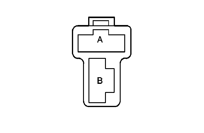
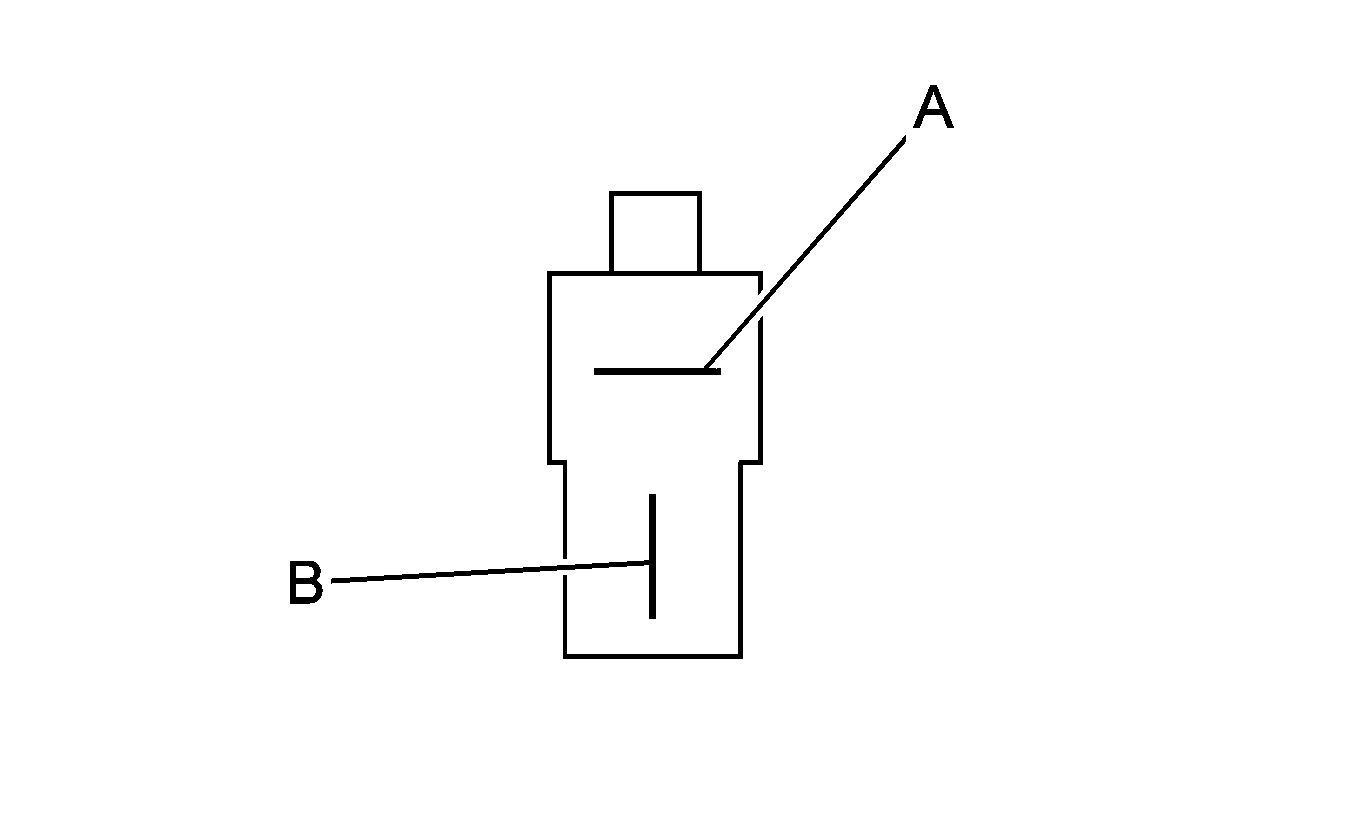
C213 Floor Harness to Auxiliary Power Harness
|
|
Connector Part Information
| Connector Part Information
|
Pin | Wire Color | Circuit No. | Function | Pin | Wire Color | Circuit No. | Function |
|---|---|---|---|---|---|---|---|
A | D-GN/RD | SA03 | Battery Positive Voltage | A | D-GN/RD | 1 | Battery Positive Voltage |
B | BK | SX03 | Ground | B | BK | 2 | Ground |
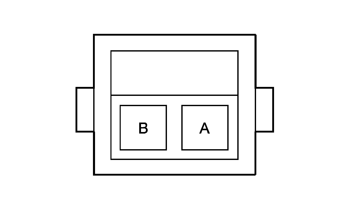
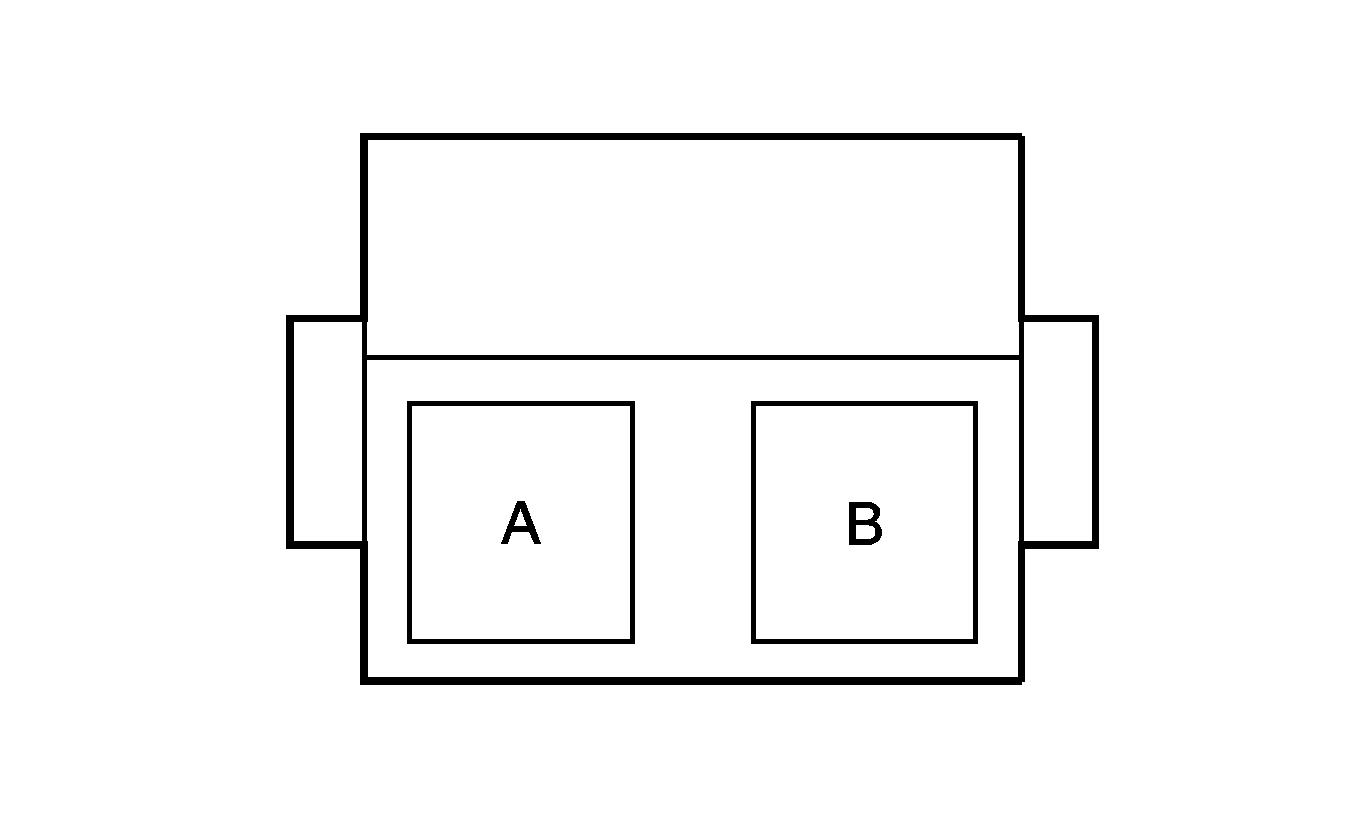
C214 Upper I/P Harness to Air Brake Pressure Gage Harness (JE4)
|
|
Connector Part Information
| Connector Part Information
|
Pin | Wire Color | Circuit No. | Function | Pin | Wire Color | Circuit No. | Function |
|---|---|---|---|---|---|---|---|
A | BK | MX06 | Ground | A | BK | 2 | Ground |
B | BK/RD | MA11 | Illumination Supply Voltage | B | BK/RD | 1 | Illumination Supply Voltage |
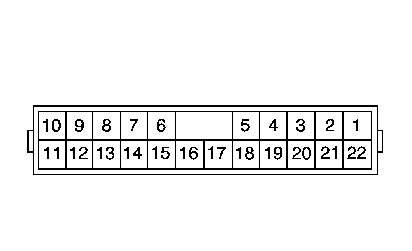
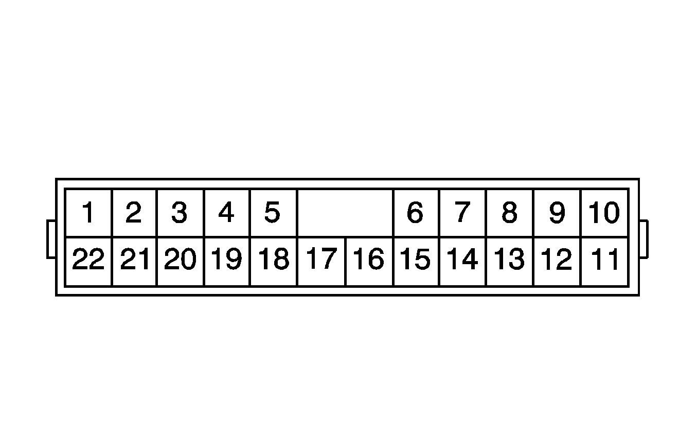
C215 Lower I/P Harness to Transmission Cab Harness (Automatic Transmission)
|
|
Connector Part Information
| Connector Part Information
|
Pin | Wire Color | Circuit No. | Function | Pin | Wire Color | Circuit No. | Function |
|---|---|---|---|---|---|---|---|
1 | GY/D-BU | TF12 | Shield | 1 | GY/D-BU | TF12 | Shield |
2 | D-BU | TF08 | CAN High | 2 | D-BU | TF08 | CAN High |
3 | WH | OA15 | Transmission Power Take-Off Enable Signal | 3 | WH | OA15 | Transmission Power Take-Off Enable Signal (Allison® LCT) |
WH | NF55 | Transmission Power Take-Off Enable Signal (Allison® MD) | |||||
4 | RD/D-GN | OA10 | Overdrive Defeat Switch Signal | 4 | RD/D-GN | OA10 | Overdrive Defeat Switch Signal (Allison® LCT) |
-- | -- | Not Used (Allison® MD) | |||||
5 | D-GN/RD | OA08 | Do Not Shift Indicator Control | 5 | D-GN/RD | OA08 | Do Not Shift Indicator Control (Allison® LCT) |
-- | -- | Not Used (Allison® MD) | |||||
6 | GY | OA07 | TCM MIL Request | 6 | GY | OA07 | TCM MIL Request (Allison® LCT) |
GY | NF06 | TCM MIL Request (Allison® MD) | |||||
7 | PK | OA03 | Ignition 1 Voltage | 7 | PK | OA03 | Ignition 1 Voltage (Allison® LCT) |
PK | NF03 | Ignition 1 Voltage (Allison® MD) | |||||
8 | OG | OA02 | Positive Battery Voltage | 8 | OG | OA02 | Positive Battery Voltage (Allison® LCT) |
OG | NF01 | Positive Battery Voltage (Allison® MD) | |||||
9 | D-BU | TF03 | CAN High | 9 | D-BU | TF03 | CAN High |
10 | GY/D-BU | TF07 | Shield | 10 | GY/D-BU | TF07 | Shield |
11 | -- | -- | Not Used | 11 | -- | -- | Not Used |
12 | BK/WH | TF04 | CAN Low | 12 | BK/WH | TF04 | CAN Low |
13 | YE | OA57 | Class 2 Serial Data | 13 | YE | OA57 | Class 2 Serial Data (Allison® LCT) |
-- | -- | Not Used (Allison® MD) | |||||
14 | D-GN/WH | NF07 | J1708 Serial Data A | 14 | -- | -- | Not Used (Allison® LCT) |
D-GN/WH | NF07 | J1708 Serial Data A (Allison® MD) | |||||
15 | D-GN | NF08 | J1708 Serial Data B | 15 | -- | -- | Not Used (Allison® LCT) |
D-GN | NF08 | J1708 Serial Data B (Allison® MD) | |||||
16 | L-BU | NF09 | Return | 16 | -- | -- | Not Used (Allison® LCT) |
L-BU | NF09 | Return (Allison® MD) | |||||
17 | PK | NF21 | Ignition 1 Voltage | 17 | -- | -- | Not Used (Allison® LCT) |
PK | NF21 | Ignition 1 Voltage (Allison® MD) | |||||
18 | YE | NF57 | Crank Voltage | 18 | -- | -- | Not Used (Allison® LCT) |
YE | NF57 | Crank Voltage (Allison® MD) | |||||
19 | YE/D-BU | NF58 | PNP/Clutch Start Switch Signal | 19 | -- | -- | Not Used (Allison® LCT) |
YE/D-BU | NF58 | PNP/Clutch Start Switch Signal (Allison® MD) | |||||
20 | BK | NU05 | Ground (Allison® MD) | 20 | BK | NU05 | Ground (Allison® MD) |
-- | -- | Not Used (Allison® LCT) | -- | -- | Not Used (Allison® LCT) | ||
21 | BK/WH | TF09 | CAN Low | 21 | BK/WH | TF09 | CAN Low |
22 | -- | -- | Not Used | 22 | -- | -- | Not Used |
C215 Lower I/P Harness to C215 Shunt (Manual Transmission)

|

|
Connector Part Information
| Connector Part Information
|
Pin | Wire Color | Circuit No. | Function | Pin | Wire Color | Circuit No. | Function |
|---|---|---|---|---|---|---|---|
1 | GY/D-BU | TF12 | Shield | 1 | GY/D-BU | TF18 | Shield (Shunt to Pin 10) |
2 | D-BU | TF08 | CAN High | 2 | D-BU | TF16 | CAN High (Shunt to Pin 9) |
3 | WH | OA15 | Transmission Power Take-Off Enable Signal | 3 | -- | -- | Not Used |
4 | RD/D-GN | OA10 | Overdrive Defeat Switch Signal | 4 | -- | -- | Not Used |
5 | D-GN/RD | OA08 | Do Not Shift Indicator Control | 5 | -- | -- | Not Used |
6 | GY | OA07 | TCM MIL Request | 6 | -- | -- | Not Used |
7 | PK | OA03 | Ignition 1 Voltage | 7 | -- | -- | Not Used |
8 | OG | OA02 | Positive Battery Voltage | 8 | -- | -- | Not Used |
9 | D-BU | TF03 | CAN High | 9 | D-BU | TF16 | CAN High (Shunt to Pin 2) |
10 | GY/D-BU | TF07 | Shield | 10 | GY/D-BU | TF18 | Shield (Shunt to Pin 1) |
11 | -- | -- | Not Used | 11 | -- | -- | Not Used |
12 | BK/WH | TF04 | CAN Low | 12 | BK/WH | TF17 | CAN Low (Shunt to Pin 21) |
13 | YE | OA57 | Class 2 Serial Data | 13 | -- | -- | Not Used |
14 | D-GN/WH | NF07 | J1708 Serial Data A | 14 | -- | -- | Not Used |
15 | D-GN | NF08 | J1708 Serial Data B | 15 | -- | -- | Not Used |
16 | L-BU | NF09 | Return | 16 | -- | -- | Not Used |
17 | PK | NF21 | Ignition 1 Voltage | 17 | -- | -- | Not Used |
18 | YE | NF57 | Crank Voltage | 18 | -- | -- | Not Used |
19 | YE/D-BU | NF58 | PNP/Clutch Start Switch Signal | 19 | -- | -- | Not Used |
20 | BK | NU05 | Ground | 20 | -- | -- | Not Used |
21 | BK/WH | TF09 | CAN Low | 21 | BK/WH | TF17 | CAN Low (Shunt to Pin 12) |
22 | -- | -- | Not Used | 22 | -- | -- | Not Used |
C216 Lower I/P Harness DNA Shunt to Lower I/P Harness

|

|
Connector Part Information
| Connector Part Information
|
Pin | Wire Color | Circuit No. | Function | Pin | Wire Color | Circuit No. | Function |
|---|---|---|---|---|---|---|---|
A | OG | WA07 | Interior Park Lamps Supply Voltage | A | OG | WA07 | Interior Park Lamps Supply Voltage |
B | BN | WA06 | Interior Park Lamps Supply Voltage | B | BN | WA06 | Interior Park Lamps Supply Voltage |
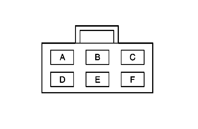
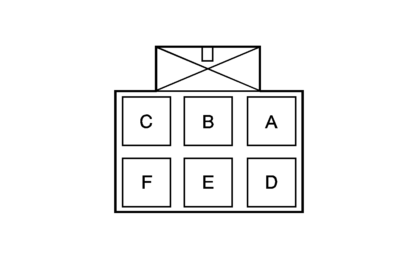
C219 Floor Harness to Transmission Cab Harness (Allison® MD Automatic Transmission)
|
|
Connector Part Information
| Connector Part Information
|
Pin | Wire Color | Circuit No. | Function | Pin | Wire Color | Circuit No. | Function |
|---|---|---|---|---|---|---|---|
A | BK/RD | OA14 | Instrument Panel Lamps Dimming Supply Voltage | A | BK/RD | OA14 | Instrument Panel Lamps Dimming Supply Voltage |
B-C | -- | -- | Not Used | B-C | -- | -- | Not Used |
D | BK | OX05 | Ground | D | BK | OX05 | Ground |
E-F | -- | -- | Not Used | E-F | -- | -- | Not Used |
C400 Battery Fusible Links to Front Chassis Harness

|

|
Connector Part Information
| Connector Part Information
|
Pin | Wire Color | Circuit No. | Function | Pin | Wire Color | Circuit No. | Function |
|---|---|---|---|---|---|---|---|
A | WH | PA21 | Battery Positive Voltage | A | RD | PA22 | Battery Positive Voltage |
B | WH | HB13 | Battery Positive Voltage | B | RD | HB01 | Battery Positive Voltage |
C402 Battery Fusible Links Battery to Front Chassis Harness

|

|
Connector Part Information
| Connector Part Information
|
Pin | Wire Color | Circuit No. | Function | Pin | Wire Color | Circuit No. | Function |
|---|---|---|---|---|---|---|---|
A | WH | PA25 | Battery Positive Voltage | A | RD | PA26 | Battery Positive Voltage |
B | WH | PA23 | Battery Positive Voltage | B | RD | PA24 | Battery Positive Voltage |
C403 Rear Chassis Harness to Front Chassis Harness

|

|
Connector Part Information
| Connector Part Information
|
Pin | Wire Color | Circuit No. | Function | Pin | Wire Color | Circuit No. | Function |
|---|---|---|---|---|---|---|---|
A | L-GN | 12 | Backup Lamp Supply Voltage | A | L-GN | BA02 | Backup Lamp Supply Voltage (Manual) |
OA59 | Backup Lamp Supply Voltage (Allison® LCT) | ||||||
NF22 | Backup Lamp Supply Voltage (Allison® MD) | ||||||
B | D-GN | 1 | Right Rear Stop/Turn Lamp Supply Voltage | B | D-GN | JA21 | Right Rear Stop/Turn Lamp Supply Voltage |
C | YE | 2 | Left Rear Stop/Turn Lamp Supply Voltage | C | YE | JA20 | Left Rear Stop/Turn Lamp Supply Voltage |
D | BN | 3 | Left/Right Tail Lamp Supply Voltage | D | BN | BA09 | Left/Right Tail Lamp Supply Voltage |
E | RD/WH | 48 | Traction Control Valve (Air) Low (JE4) | E | RD/WH | BB51 | Traction Control Valve (Air) Low (JE4) |
-- | -- | Not Used (JE3) | -- | -- | Not Used (JE3) | ||
F | PK | 47 | Traction Control Valve (Air) High (JE4) | F | PK | BB50 | Traction Control Valve (Air) High (JE4) |
-- | -- | Not Used (JE3) | -- | -- | Not Used (JE3) | ||
G | -- | -- | Not Used | G | -- | -- | Not Used |
H | L-GN/WH | 75 | Differential Lock Switch Signal | H | YE/BK | NB02 | Differential Lock Switch Signal |
J | RD | 73 | Left Rear - Middle Wheel Speed Sensor Low Reference (HPE) | J | RD | BB31 | Left Rear - Middle Wheel Speed Sensor Low Reference (HPE) |
-- | -- | Not Used (w/o HPE) | -- | -- | Not Used (w/o HPE) | ||
K | BK | 72 | Left Rear - Middle Wheel Speed Sensor Signal (HPE) | K | BK | BB30 | Left Rear - Middle Wheel Speed Sensor Signal (HPE) |
-- | -- | Not Used (w/o HPE) | -- | -- | Not Used (w/o HPE) | ||
L | WH | 71 | Right Rear - Middle Wheel Speed Sensor Low Reference (HPE) | L | WH | BB29 | Right Rear - Middle Wheel Speed Sensor Low Reference (HPE) |
-- | -- | Not Used (w/o HPE) | -- | -- | Not Used (w/o HPE) | ||
M | BN | 70 | Right Rear - Middle Wheel Speed Sensor Signal (HPE) | M | BN | BB28 | Right Rear - Middle Wheel Speed Sensor Signal (HPE) |
-- | -- | Not Used (w/o HPE) | -- | -- | Not Used (w/o HPE) | ||
N | BK | 5 | Ground | N | BK | BX14 | Ground |
P | -- | -- | Not Used | P | -- | -- | Not Used |
R | D-BU/RD | 78 | Air Suspension Dump Switch Signal | R | D-BU/RD | CF02 | Air Suspension Dump Switch Signal |
S | BN | 49 | Low Air Pressure Switch Signal - Secondary (JE4) | S | BN | MA10 | Low Air Pressure Switch Signal (JE4) |
-- | -- | Not Used (JE3) | -- | -- | Not Used (JE3) |
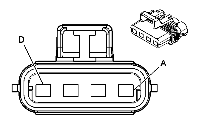
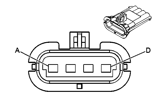
C404 Rear Chassis Harness to Two-Speed Rear Axle Harness
|
|
Connector Part Information
| Connector Part Information
|
Pin | Wire Color | Circuit No. | Function | Pin | Wire Color | Circuit No. | Function |
|---|---|---|---|---|---|---|---|
A | GY | 82 | Shift Motor Relay - Control | A | BN | 241 | Shift Motor Relay - Control |
B | PK | 81 | Ignition 2 Voltage | B | GY/BK | 1467 | Ignition 2 Voltage |
C | BK | 83 | Ground | C | BK | 450 | Ground |
D | -- | -- | Not Used | D | -- | -- | Not Used |
C405 Rear Chassis Harness to Front Chassis Harness

|

|
Connector Part Information
| Connector Part Information
|
Pin | Wire Color | Circuit No. | Function | Pin | Wire Color | Circuit No. | Function |
|---|---|---|---|---|---|---|---|
A | D-GN/WH | 36 | Left Rear Wheel Speed Sensor Low Reference (JE4) | A | D-GN/WH | BB27 | Left Rear Wheel Speed Sensor Low Reference (JE4) |
D-GN/WH | 63 | Left Rear Wheel Speed Sensor Low Reference (JE3) | D-GN/WH | BG27 | Left Rear Wheel Speed Sensor Low Reference (JE3) | ||
B | D-BU/WH | 35 | Left Rear Wheel Speed Sensor Signal (JE4) | B | D-BU/WH | BB26 | Left Rear Wheel Speed Sensor Signal (JE4) |
D-BU/WH | 62 | Left Rear Wheel Speed Sensor Signal (JE3) | D-BU/WH | BG26 | Left Rear Wheel Speed Sensor Signal (JE3) | ||
C | BK/WH | 34 | Right Rear Wheel Speed Sensor Low Reference (JE4) | C | BK/WH | BB25 | Right Rear Wheel Speed Sensor Low Reference (JE4) |
BK/WH | 61 | Right Rear Wheel Speed Sensor Low Reference (JE3) | BK/WH | BG25 | Right Rear Wheel Speed Sensor Low Reference (JE3) | ||
D | D-GN/BK | 33 | Right Rear Wheel Speed Sensor Signal (JE4) | D | D-GN/BK | BB24 | Right Rear Wheel Speed Sensor Signal (JE4) |
D-GN/BK | 60 | Right Rear Wheel Speed Sensor Signal (JE3) | D-GN/BK | BG24 | Right Rear Wheel Speed Sensor Signal (JE3) | ||
E | GY | 41 | Shield (JE4) | E | GY | BB14 | Shield (JE4) |
-- | -- | Not Used (JE3) | -- | -- | Not Used (JE3) | ||
F | BK | 39 | Right Rear Modulator Supply Voltage (JE4) | F | BK | BB42 | Right Rear Modulator Supply Voltage (JE4) |
-- | -- | Not Used (JE3) | -- | -- | Not Used (JE3) | ||
G | RD | 38 | Right Rear Modulator Hold Control (JE4) | G | RD | BB41 | Right Rear Modulator Hold Control (JE4) |
-- | -- | Not Used (JE3) | -- | -- | Not Used (JE3) | ||
H | WH | 37 | Right Rear Modulator Exhaust Control (JE4) | H | WH | BB40 | Right Rear Modulator Exhaust Control (JE4) |
-- | -- | Not Used (JE3) | -- | -- | Not Used (JE3) | ||
J | GY/BK | 46 | Shield (JE4) | J | GY/BK | BB49 | Shield (JE4) |
-- | -- | Not Used (JE3) | -- | -- | Not Used (JE3) | ||
K | D-GN | 44 | Left Rear Modulator Supply Voltage (JE4) | K | D-GN | BB47 | Left Rear Modulator Supply Voltage (JE4) |
-- | -- | Not Used (JE3) | -- | -- | Not Used (JE3) | ||
L | YE | 43 | Left Rear Modulator Hold Control (JE4) | L | YE | BB46 | Left Rear Modulator Hold Control (JE4) |
-- | -- | Not Used (JE3) | -- | -- | Not Used (JE3) | ||
M | D-BU | 42 | Left Rear Modulator Exhaust Control (JE4) | M | D-BU | BB45 | Left Rear Modulator Exhaust Control (JE4) |
-- | -- | Not Used (JE3) | -- | -- | Not Used (JE3) | ||
N | -- | -- | Not Used | N | -- | -- | Not Used |
P | BK | 83 | Ground | P | BK | FZ04 | Ground |
R | GY | 82 | Shift - Signal | R | RD/D-BU | FC02 | Shift - Signal |
S | PK | 81 | Ignition 1 Voltage | S | PK | FC01 | Ignition 1 Voltage |
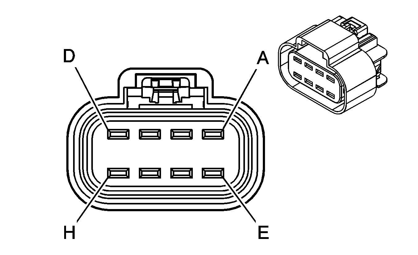
C406 Tractor/Trailer Harness to Front Chassis Harness (JE4, RQ2 and U86 or JE4 and RQ3)
|
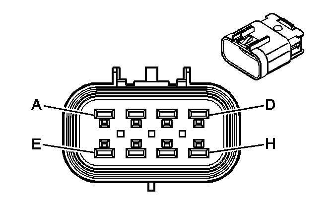
|
Connector Part Information
| Connector Part Information
|
Pin | Wire Color | Circuit No. | Function | Pin | Wire Color | Circuit No. | Function |
|---|---|---|---|---|---|---|---|
A | D-BU | MF05 | ABS Continuous Shared Power | A | D-BU | MF05 | Battery Positive Voltage |
B | BN | MF06 | Tail and License Plate Lamps Supply Voltage | B | BN | MF06 | Tail and License Plate Lamps Supply Voltage |
C | D-GN | MF04 | Right Turn/Hazard Lamps Supply Voltage | C | D-GN | MF04 | Right Turn/Hazard Lamps Supply Voltage |
D | RD | MF03 | Stop Lamps Supply Voltage and ABS Backup Power | D | RD | MF03 | Stop Lamps Supply Voltage and ABS Backup Power |
E | YE | MF02 | Left Turn/Hazard Lamps Supply Voltage | E | YE | MF02 | Left Turn/Hazard Lamps Supply Voltage |
F | BK | MF01 | Marker Lamps Supply Voltage | F | BK | MF01 | Marker Lamps Supply Voltage |
G-H | -- | -- | Not Used | G-H | -- | -- | Not Used |
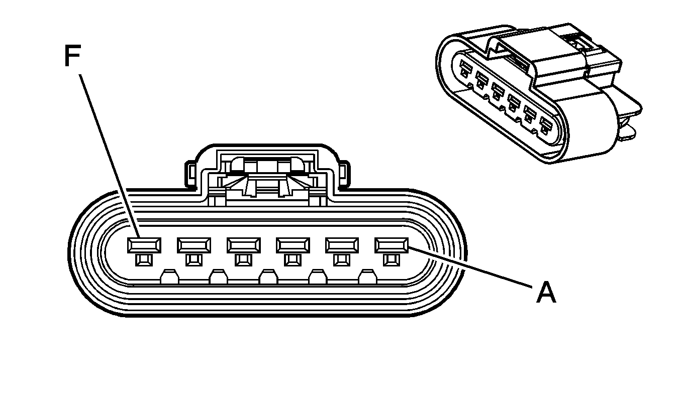
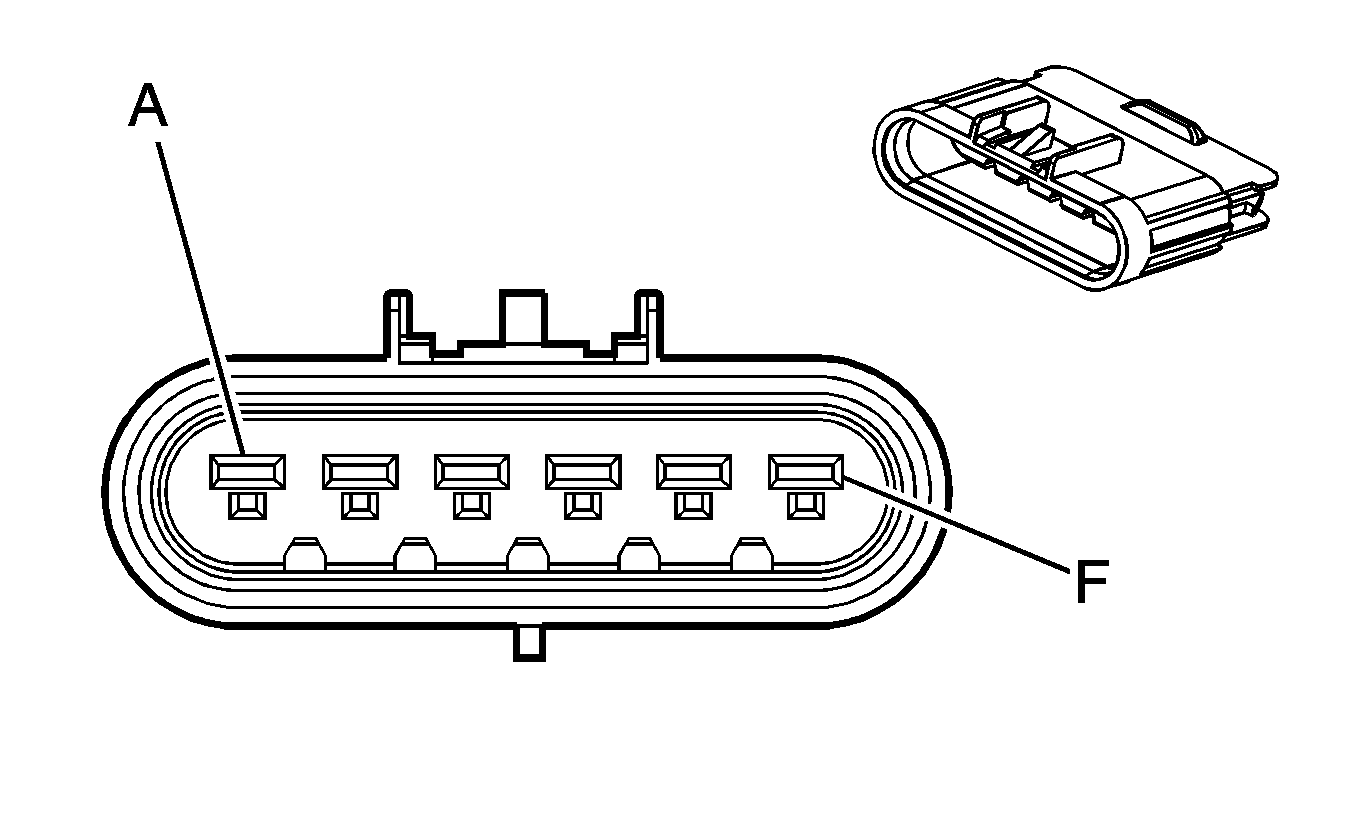
C407 Transmission Harness to Engine Chassis Harness (Manual Transmission)
|
|
Connector Part Information
| Connector Part Information
|
Pin | Wire Color | Circuit No. | Function | Pin | Wire Color | Circuit No. | Function |
|---|---|---|---|---|---|---|---|
A | L-GN | 24 | Backup Lamp Supply Voltage | A | D-GN | BA02 | Backup Lamp Supply Voltage |
B | PU/WH | 821 | VSS High Signal | B | WH | DF38 | VSS High Signal |
C | L-GN/BK | 822 | VSS Low Signal | C | BK | DF39 | VSS Low Signal |
D | -- | -- | Not Used | D | -- | -- | Not Used |
E | PK | 441 | Ignition 1 Voltage | E | RD | BA01 | Ignition 1 Voltage |
F | -- | -- | Not Used | F | -- | -- | Not Used |
C411 Front Chassis Harness to Fuel Tank Harness

|

|
Connector Part Information
| Connector Part Information
|
Pin | Wire Color | Circuit No. | Function | Pin | Wire Color | Circuit No. | Function |
|---|---|---|---|---|---|---|---|
A | VT | CF97 | Fuel Level Sensor Signal - Primary | A | PU | 7 | Fuel Level Sensor Signal - Primary (Base) |
10 | Fuel Level Sensor Signal - Primary (Right Tank) | ||||||
1 | Fuel Level Sensor Signal - Primary (Dual Tanks) | ||||||
B | BK/YE | CF96 | Low Reference | B | BK/RD | 8 | Low Reference (Base) |
11 | Low Reference (Right Tank) | ||||||
2 | Low Reference (Dual Tanks) | ||||||
C | BK | CU22 | Ground | C | BK | 9 | Ground (Base) |
12 | Ground (Right Tank) | ||||||
3 | Ground (Dual Tanks) | ||||||
D | D-BU | CF99 | Fuel Level Sensor Signal - Secondary | D | -- | -- | Not Used (Single Tank) |
D-BU | 4 | Fuel Level Sensor Signal - Secondary (Dual Tanks) | |||||
E | BK/RD | CF98 | Low Reference | E | -- | -- | Not Used (Single Tank) |
BK/RD | 5 | Low Reference (Dual Tanks) | |||||
F | BK | CU23 | Ground | F | -- | -- | Not Used (Single Tank) |
BK | 6 | Ground (Dual Tanks) |
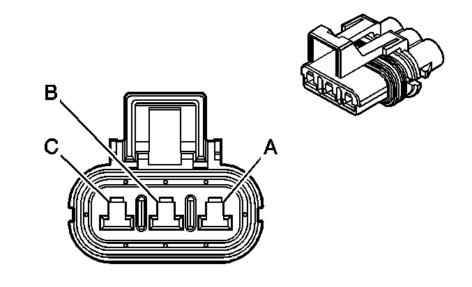
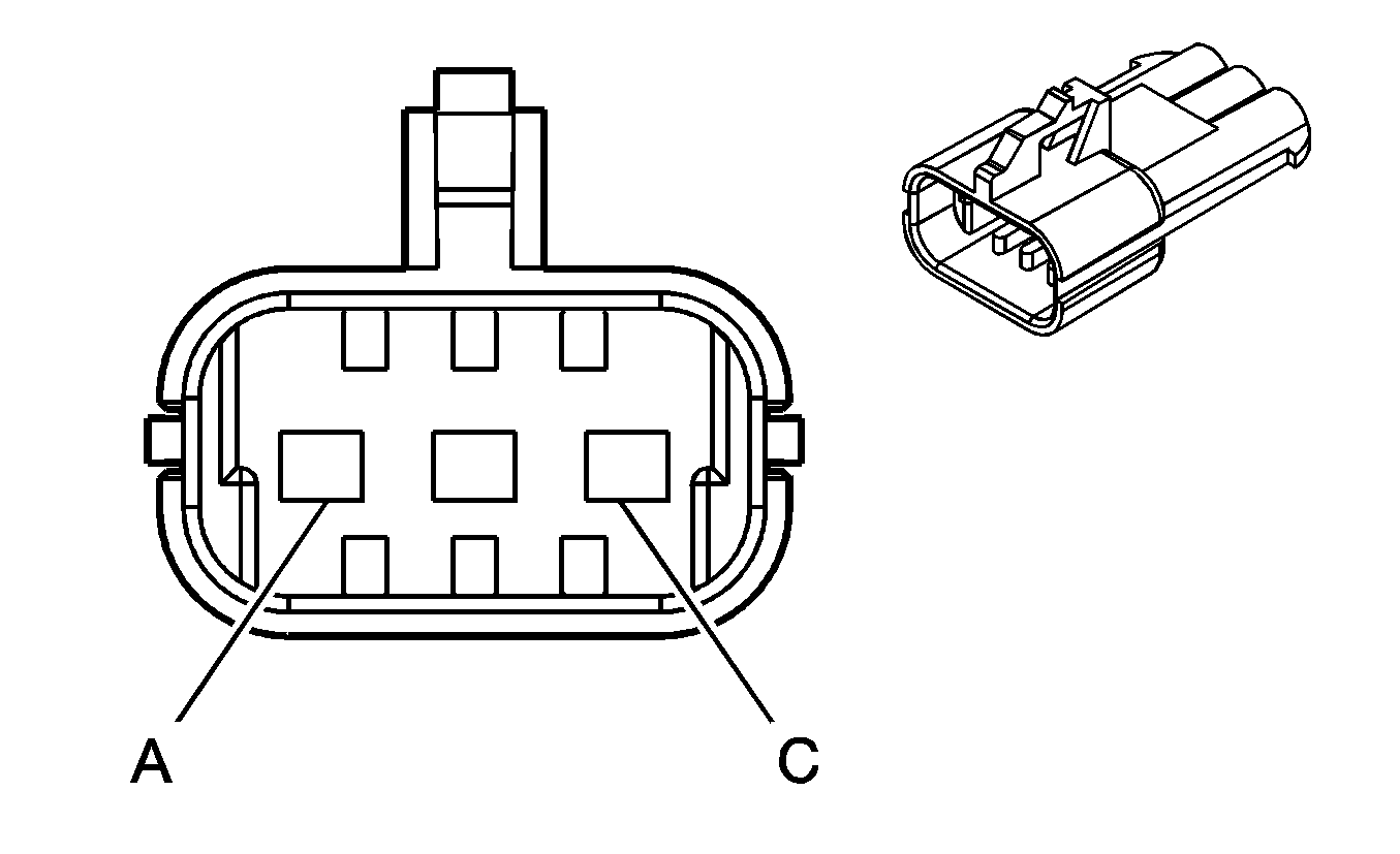
C421 Front Chassis Harness to Air Compressor Harness (K16)
|
|
Connector Part Information
| Connector Part Information
|
Pin | Wire Color | Circuit No. | Function | Pin | Wire Color | Circuit No. | Function |
|---|---|---|---|---|---|---|---|
A | RD | BG29 | Battery Positive Voltage | A | OG | 1840 | Battery Positive Voltage |
B | BN | BG31 | Low Air Pressure Switch Signal | B | RD | 2672 | Low Air Pressure Switch Signal |
C | BK | BT06 | Ground | C | BK | 350 | Ground |
C501 Lower I/P Harness to Left Door Harness

|

|
Connector Part Information
| Connector Part Information
|
Pin | Wire Color | Circuit No. | Function | Pin | Wire Color | Circuit No. | Function |
|---|---|---|---|---|---|---|---|
A | BN | BA27 | Side Marker Lamp | A | BN | 20 | Side Marker Lamp |
B | L-BU | JA14 | Left Turn Signal Lamps Supply Voltage | B | L-BU | 25 | Left Turn Signal Lamps Supply Voltage |
C | OG | UA04 | Power Window Relay Signal | C | OG | 7 | Power Window Relay Signal |
D | BK | BX13 | Ground | D | BK | 4 | Ground |
E | OG | WA02 | Outside Mirror Switch Signal | E | OG | 32 | Outside Mirror Switch Signal |
F | L-GN/WH | UA07 | Power Window Lock | F | L-GN/WH | 8 | Power Window Lock |
G | L-GN/RD | UA05 | Power Window Down Signal | G | L-GN/RD | 9 | Power Window Down Signal |
H | L-GN/BK | UA06 | Power Window Up Signal | H | L-GN/BK | 10 | Power Window Up Signal |
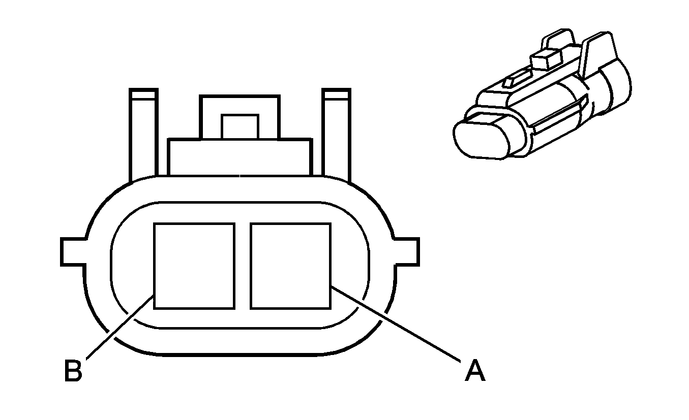
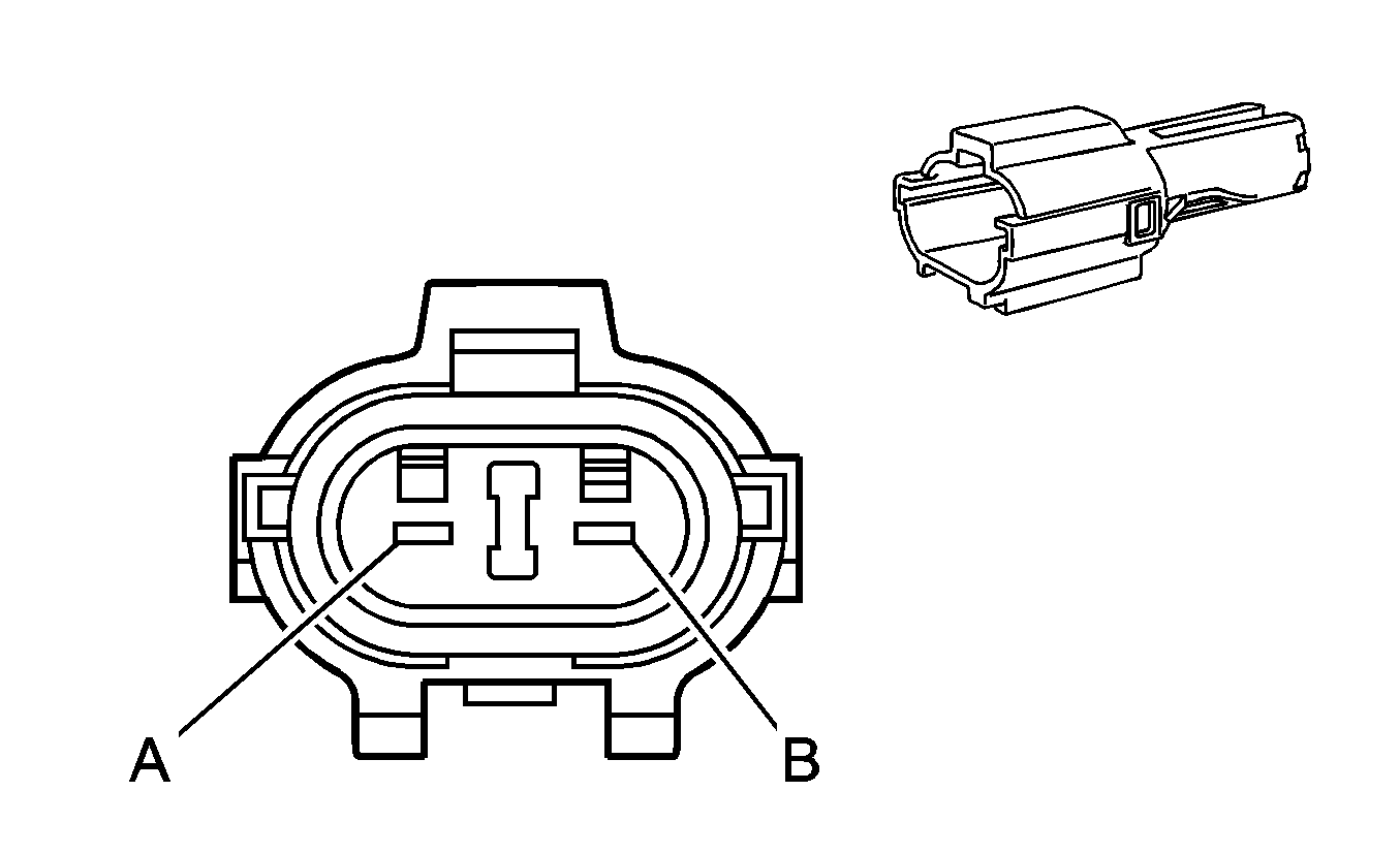
C503 Left Door Harness to Left Outside Rearview Mirror Connector
|
|
Connector Part Information
| Connector Part Information
|
Pin | Wire Color | Circuit No. | Function | Pin | Wire Color | Circuit No. | Function |
|---|---|---|---|---|---|---|---|
A | BK | 33 | Ground | A | BK | 2 | Ground |
B | OG | 32 | Tail Lamp Supply Voltage (DNA) | B | OG | 1 | Tail Lamp Supply Voltage (DNA) |
Driver Mirror Heating Element Supply Voltage (DNN) | Driver Mirror Heating Element Supply Voltage (DNN) |
C601 Lower I/P Harness to Right Door Harness

|

|
Connector Part Information
| Connector Part Information
|
Pin | Wire Color | Circuit No. | Function | Pin | Wire Color | Circuit No. | Function |
|---|---|---|---|---|---|---|---|
A | BN | BA26 | Side Marker Lamp | A | BN | 20 | Side Marker Lamp |
B | D-BU | JA18 | Right Turn Signal Lamps Supply Voltage | B | D-BU | 25 | Right Turn Signal Lamps Supply Voltage |
C | OG | UA02 | Ignition 1 Voltage | C | OG | 3 | Ignition 1 Voltage |
D | BK | BX12 | Ground | D | BK | 4 | Ground |
E | OG | WA05 | Outside Mirror Switch Signal | E | OG | 32 | Outside Mirror Switch Signal |
F | L-GN/WH | UA07 | Power Window Lock Signal | F | L-GN/WH | 8 | Power Window Lock Signal |
G | L-GN/RD | UA05 | Power Window Down Signal | G | L-GN/RD | 9 | Power Window Down Signal |
H | L-GN/BK | UA06 | Power Window Up Signal | H | L-GN/BK | 10 | Power Window Up Signal |
C603 Right Outside Rearview Mirror Connector to Right Door Harness

|

|
Connector Part Information
| Connector Part Information
|
Pin | Wire Color | Circuit No. | Function | Pin | Wire Color | Circuit No. | Function |
|---|---|---|---|---|---|---|---|
A | OG | 1 | Tail Lamp Supply Voltage (DNA) | A | OG | 32 | Tail Lamp Supply Voltage (DNA) |
Passenger Mirror Heating Element Supply Voltage (DNN) | Passenger Mirror Heating Element Supply Voltage (DNN) | ||||||
B | BK | 2 | Ground | B | BK | 33 | Ground |
