For 1990-2009 cars only
Removal Procedure
- Turn the crankshaft to position the Number 1 cylinder at top dead center.
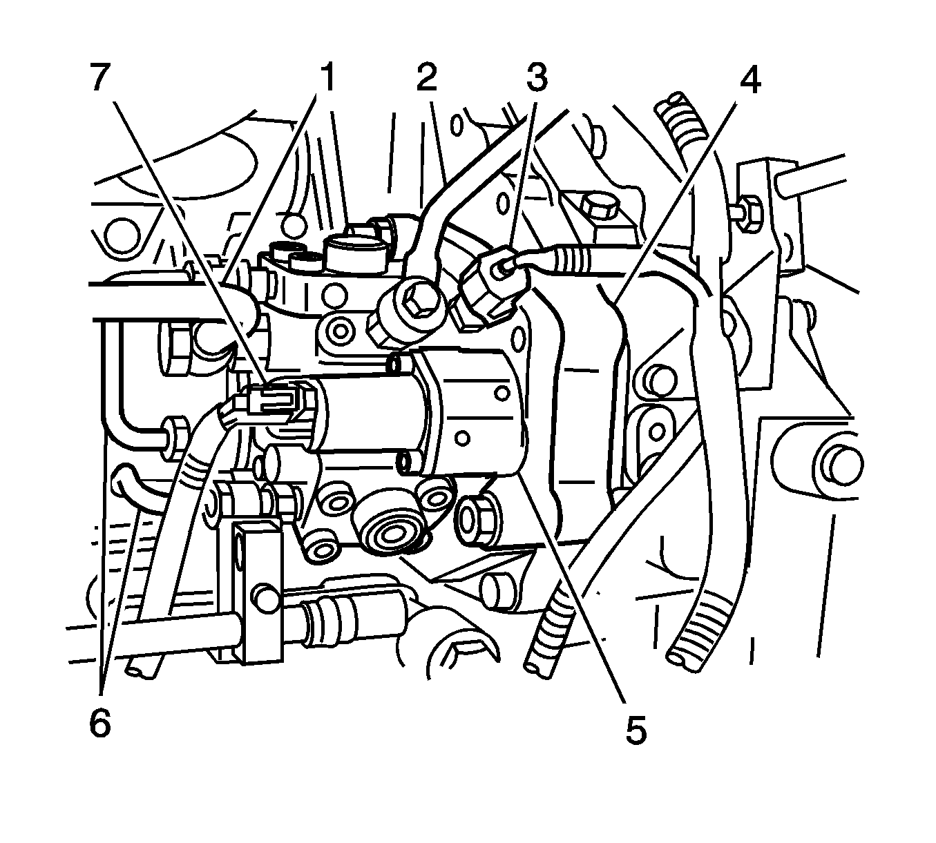
- Disconnect the electrical connector at the fuel temperature sensor (3).
- Disconnect the electrical connector at the suction control valve (7).
- Remove the fuel suction pipe (1) from the fuel supply pump (5).
- Remove the fuel filter leak off pipe (2) from the supply pump (5), common rail and the return pipe.
- Remove the fuel common rail pipe (6) from the supply pump (5) and the common rail.
- Remove the fuel pipe clamp fasteners from the fuel pipe clamps and position the fuel suction pipe (1) and the fuel feed pipe out of the way.
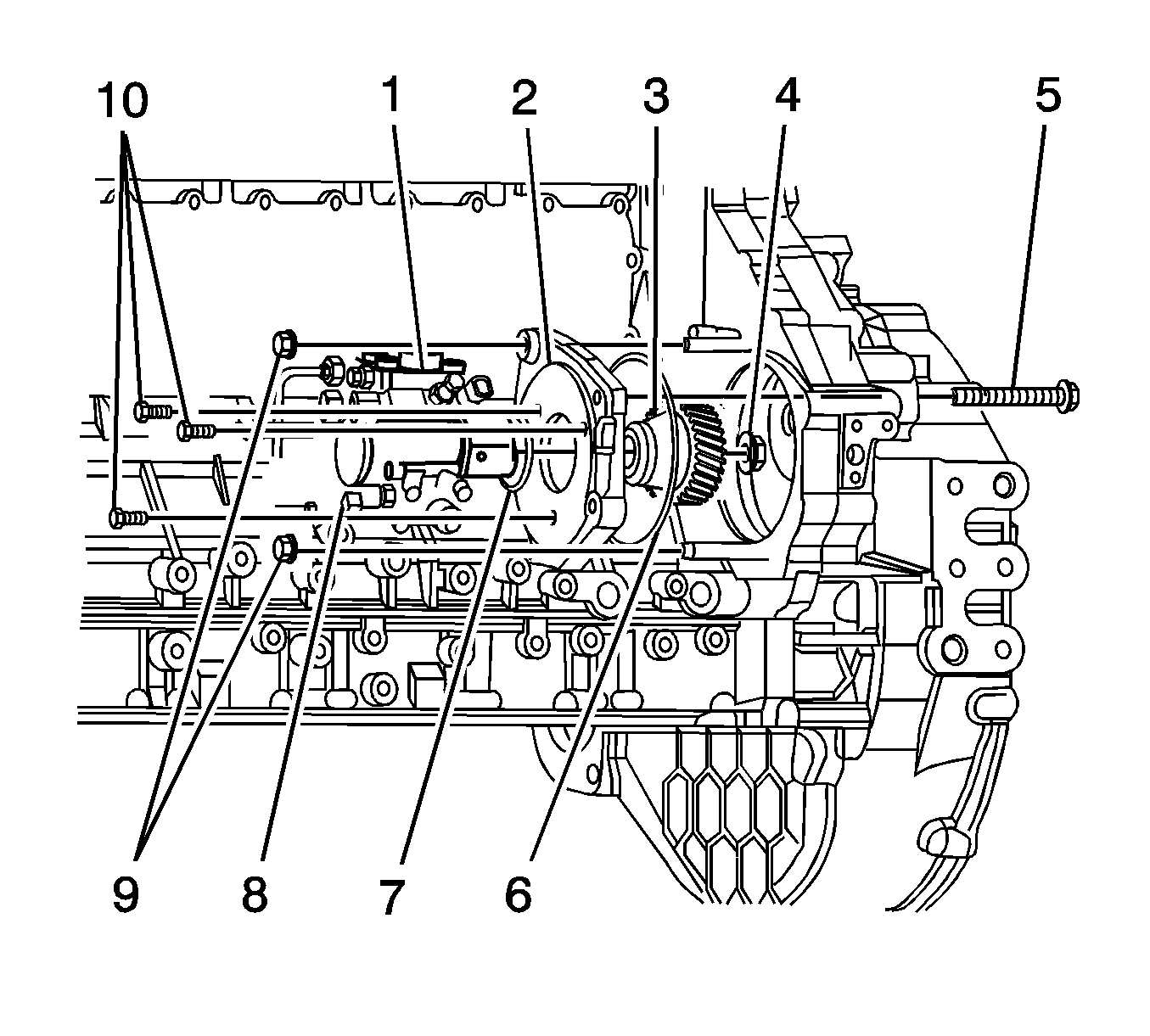
- Remove the bracket nuts (9) and bolts (5, 10).
- Remove the fuel supply pump (1) with the bracket (2) from the engine.
- If required, remove the gear nut (4), the gear (3) and the key from the fuel supply pump shaft.
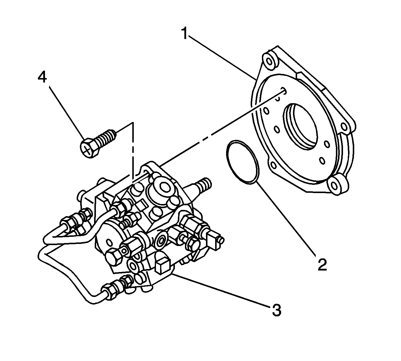
- If required, remove the bracket (1) and O-ring (2) from the fuel supply pump (3).
Installation Procedure
- Ensure that cylinder Number 1 is at top dead center.
- If required, install the NEW O-ring (2) and the bracket (1) to the fuel supply pump (3) with 3 bolts (4).
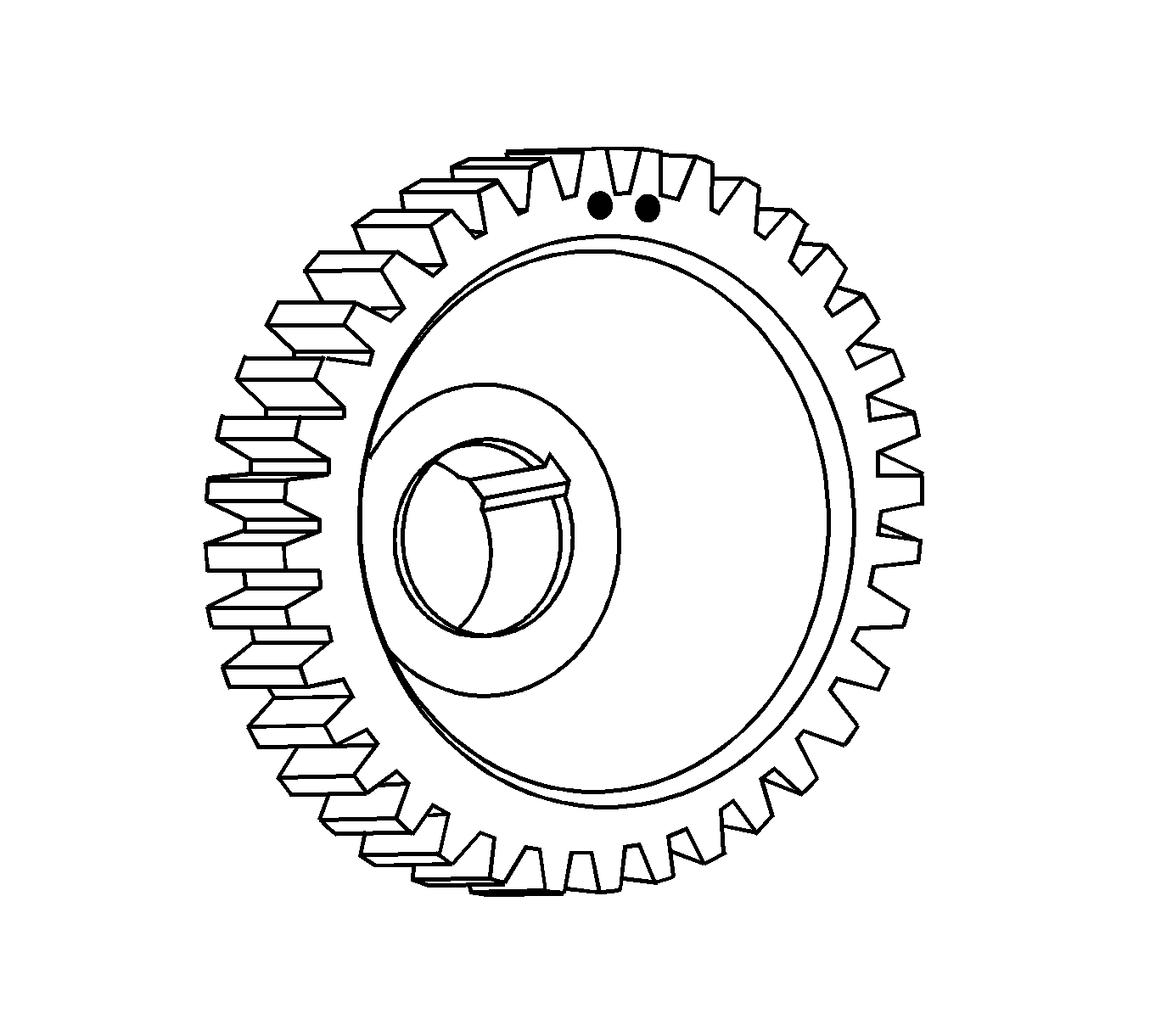
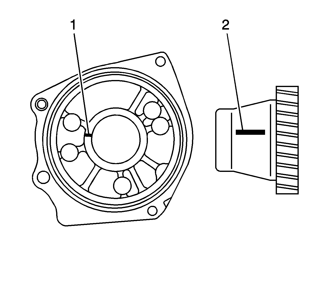
- Paint the gear teeth directly above the punch mark.
- Attach the key to the fuel supply pump shaft.
- Install the gear (3) and nut (4).
- Align the fuel supply pump bracket mark (1) and the gear punch mark (2).
- Fit the new gasket (6) to the fuel supply pump bracket (2).
- Install the fuel supply pump (1) to the cylinder block.
- Tighten the fuel supply pump nuts (9) and bolt (5).
- Ensure that cylinder Number 1 is at top dead center.
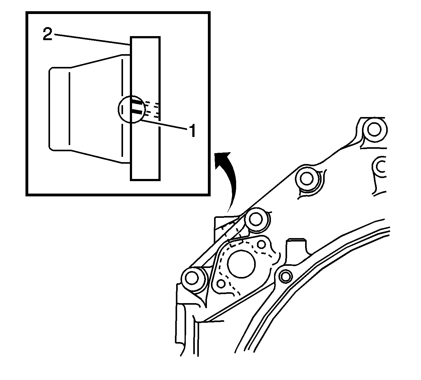
- Inspect the gear position through the inspection hole at the top of the housing. The painted portion (1) of the gear (2) must be visible through the hole. If it is not, the pump is incorrectly installed. Repeat the installation procedure.
- Using new gaskets, install the fuel common rail pipe (6) to the fuel supply pump (5) and the common rail.
- Using new gaskets, install the fuel filter leak off pipe (2) to the fuel supply pump (5).
- Using new gaskets, install the fuel suction pipe (1) to the fuel supply pump (5), common rail and the return port.
- Install the fuel pipe clamp fasteners to all fuel pipes.
- Connect the fuel temperature sensor electrical connector (3).
- Connect the suction control valve electrical connector (7).
- Bleed (prime) the fuel system and inspect for leaks. Refer to Fuel System Bleeding.
Notice: Refer to Fastener Notice in the Preface section.

Tighten
Tighten the bolts to 19 N·m (14 lb ft).

Tighten
Tighten the gear nut to 64 N·m (47 lb ft).

Tighten
| • | Tighten the nuts (9) to 50 N·m (37 lb ft). |
| • | Tighten the bolts (5) to 76 N·m (56 lb ft). |

Tighten
Tighten the nut to 44 N·m (32 lb ft).
