GM Service Manual Online
For 1990-2009 cars only

Disc Brakes System Description Front
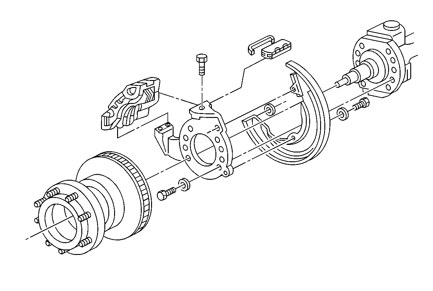

Object Number: 237270  Size: MF

All hydraulic foundation brakes are disc brake type. The Dayton-Walther rail slider type disc brake caliper is used on the 8,100 lb front axle. All other axles use the Bendix® rail slider type disc brake caliper.
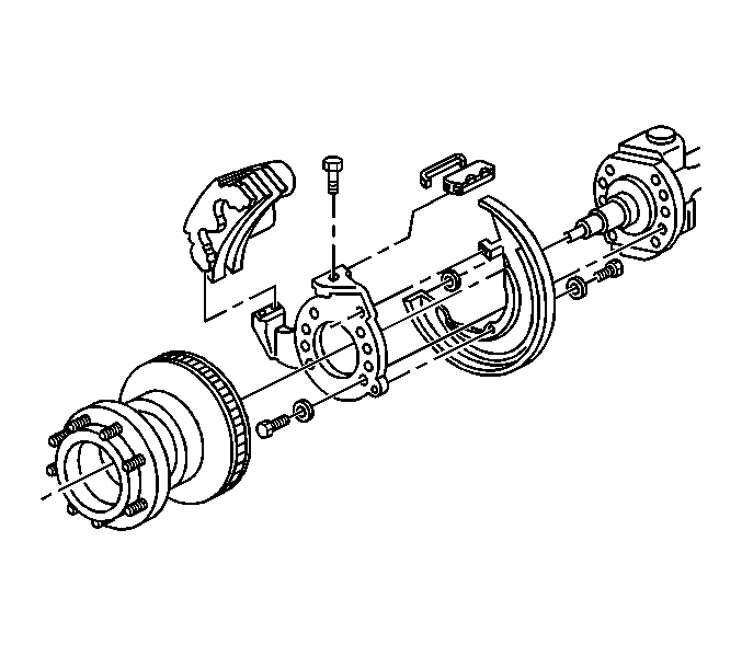

Object Number: 237266  Size: SH

The front and rear disc brake assembly consists of the following components:

    • The brake caliper
    • The brake rotor (with a hub, or with a wheel)
    • Brake pads
    • The brake caliper mounting plate
    • The brake shield

The brake rotor is bolted to the front hub or wheel. The rotor turns with the tire and wheel assembly. The brake caliper housing has machined bores and pistons. A seal in a groove of the wall in each bore provides a hydraulic seal and retracts the piston when fluid pressure is relieved. A dust boot keeps the piston bore clean. A metal heat shield protects the dust boot from the heat caused by braking friction. The brake caliper is mounted by a brake caliper retainer and the brake caliper retainer spring to the stationary brake caliper mounting plate. The brake caliper mounting plate and the brake shield is bolted to the steering knuckle.

The brake pad assemblies are held in place on each side of the brake rotor. The outer brake pad moves with the brake caliper housing. Depending on axle size, the inner brake pad is held in place by either the brake caliper mounting plate or the brake caliper housing. All original equipment brake pad linings are asbestos free.

Applying the brake pedal causes hydraulic pressure to move the brake caliper pistons. This causes the brake pads to clamp the brake rotor. The brake caliper adjusts its clamping position by sliding laterally in the support rails on the brake caliper mounting plate.

Releasing the brake pedal relieves the pressure applied to the brake caliper pistons. The pistons are pulled back in the bore by the action of the square cut piston seals returning to their original shape. This allows for a running clearance between the brake pad linings and the brake rotor.

Disc Brakes System Description Rear

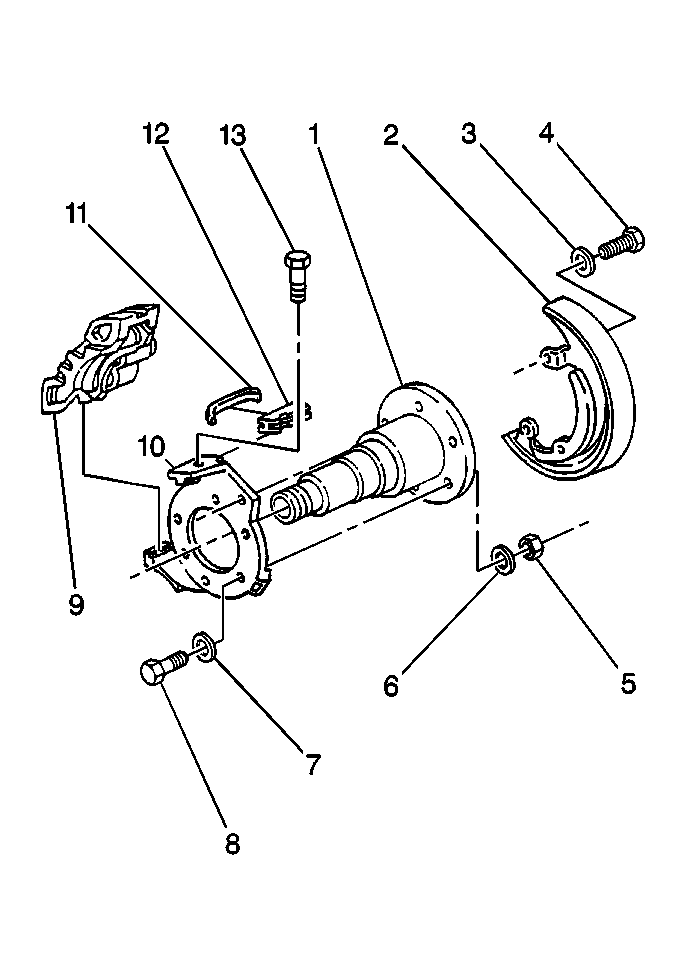
Rear Disc Brake Components (Dayton-Walther)

Object Number: 237280  Size: MH
(1)Rear Axle
(2)Brake Shield
(3)Washer
(4)Bolt
(5)Nut
(6)Washer
(7)Washer
(8)Brake Caliper Mounting Plate Bolt
(9)Brake Caliper
(10)Brake Caliper Mounting Plate
(11)Brake Caliper Retainer Spring
(12)Brake Caliper Retainer
(13)Brake Caliper Retainer Screw

Rear Disc Brake Components (Bendix®)


Object Number: 237274  Size: MH
(1)Rear Axle
(2)Brake Shield
(3)Washer
(4)Nut
(5)Brake Caliper Retainer Screw
(6)Brake Caliper Retainer
(7)Brake Caliper Retainer Spring
(8)Brake Caliper
(9)Brake Caliper Mounting Plate Bolt
(10)Washer
(11)Brake Caliper Mounting Plate

All hydraulic foundation brakes are disc brake type. The Dayton-Walther rail slider type disc brake caliper is used on the 15,000 lb rear axle. All other axles use the Bendix® rail slider type disc brake caliper.

The front and rear disc brake assembly consists of the following components:

    • The brake caliper
    • The brake rotor (with a hub, or with a wheel)
    • Brake pads
    • The brake caliper mounting plate
    • The brake shield

The brake rotor is bolted to the front hub or wheel. The rotor turns with the tire and wheel assembly. The brake caliper housing has machined bores and pistons. A seal in a groove of the wall in each bore provides a hydraulic seal and retracts the piston when fluid pressure is relieved. A dust boot keeps the piston bore clean. A metal heat shield protects the dust boot from the heat caused by braking friction. The brake caliper is mounted by a brake caliper retainer and the brake caliper retainer spring to the stationary brake caliper mounting plate. The brake caliper mounting plate and the brake shield is bolted to the steering knuckle.

The brake pad assemblies are held in place on each side of the brake rotor. The outer brake pad moves with the brake caliper housing. Depending on axle size, the inner brake pad is held in place by either the brake caliper mounting plate or the brake caliper housing. All original equipment brake pad linings are asbestos free.

Applying the brake pedal causes hydraulic pressure to move the brake caliper pistons. This causes the brake pads to clamp the brake rotor. The brake caliper adjusts its clamping position by sliding laterally in the support rails on the brake caliper mounting plate.

Releasing the brake pedal relieves the pressure applied to the brake caliper pistons. The pistons are pulled back in the bore by the action of the square cut piston seals returning to their original shape. This allows for a running clearance between the brake pad linings and the brake rotor.